Table of Contents
Advertisement
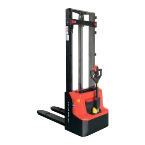
Service & Maintenance Manual
Electric Pallet Truck
PSL-type Stacker(PS E12B / PS E12N)
WARNING
Do not use the pallet truck before reading and
understanding these operating instructions.
NOTE:
Please check the designation of your present
type at the last page of this document as well
as on the ID-plate.
Keep for future reference.
1
Advertisement
Table of Contents
Troubleshooting


Need help?
Do you have a question about the PS E12B and is the answer not in the manual?
Questions and answers
Ошибка 02А54. Штабелёр работает, на какую неисправность указывает данная ошибка