Advertisement
Quick Links
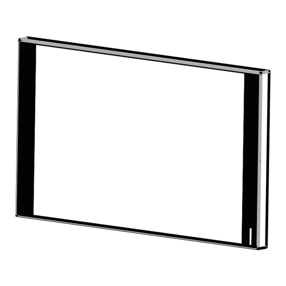
Before using the device, check the device model and ensure that the shipped box includes the following items:
S567
Allen wrench
M4x20 crosshead screw
ST4x20 crosshead screw
Speaker
Touch Screen
Speaker
1
Wall-mounting bracket (USA)
2
8-Pin cable
2
#6-30 Phillips machine screw
2
Diode
Microphone
1
Wall-mounting bracket (EU)
1
10-Pin cable
1
ST3x20 crosshead screw
1
Sensor
Microphone
S567
S567
1
M2x5 hex socket screw
1
Foam
2
Plastic wall anchor
Status Light
Speaker
2
2
2
Speaker
Advertisement

Related Manuals for Akuvox S567


Summary of Contents for Akuvox S567
- Page 1 S567 Before using the device, check the device model and ensure that the shipped box includes the following items: M2x5 hex socket screw Wall-mounting bracket (USA) Wall-mounting bracket (EU) S567 10-Pin cable Foam Allen wrench 8-Pin cable #6-30 Phillips machine screw...
- Page 2 S567 Before You Start Tools needed (not included in shipped box) Cat Ethernet Cable Crosshead Screwdriver Voltage and Current Specifications It is suggested that use PoE or 12VDC 1.5A power adapter to power on device. AWG Sizes and Properties Table...
- Page 3 5.Use wet cloth clean device surface softly, and then wipe the surface with dry cloth for cleaning the device. 6.If there is abnormal situation of the device, including uncommon sound and smell, please power off the device and contact Akuvox Technical Team immediately. Wiring Interface To protect the device from potential damage caused by over-voltage, it is recommended to wire a diode into the circuit.
- Page 4 S567 Inst Step 1: Bracket Installation With 86 junction box in the wall Arrow should be upward Fix the wall-mounting bracket(EU) on the 86 junction box with two M4x20 crosshead screws, please ensure the bracket against to wall. With 118 junction box in the wall...
- Page 5 S567 Without electrical junction box in the wall Cut out a square hole on the wall with the dimension 52*48*12mm (height*width*depth). As shown in the figure, use a 6mm electric drill to make two holes in parallel, each with a depth of 20mm, and ensure they are spaced 60mm apart.
- Page 6 S567 Tilt the device 15°and align the slots on the back cover with the hooks on the bracket. Then press down the device and make it against the wall. Use Allen wrench to secure two M2x5 hex socket screws into the bottom of the device.
- Page 7 S567 Device Removal Use Allen wrench to remove the two M2x5 crosshead screws on the bottom of the device. Tilt the device 15° as shown in the figure and push up it to remove the device. Application Network Topology SIP Video Phone...
- Page 8 1. Akuvox warranty does not cover intentional mechanical damage or destruction caused by improper installation. 2. Do not attempt to modify, alternate, maintain, or repair device by yourself. Akuvox warranty does not apply to damages caused by anyone who is not representative of Akuvox or an Akuvox authorized service provider. Please contact Akuvox Technical Team if the device need to be repaired.
Need help?
Do you have a question about the S567 and is the answer not in the manual?
Questions and answers