
Related Manuals for Smith & Noble Vertical Cellular Shades


Summary of Contents for Smith & Noble Vertical Cellular Shades
- Page 1 Cellular Shade Collection Vertical Cellular, Split Stack, and Smart Shades Installation Instructions Rev. 04/24...
- Page 2 CONTENTS Smith & Noble offers only the Rechargeable Battery Wand and Satellite Rechargeable Battery Wand power options on Smart Shades. GETTING STARTED .................... 3 Product View ......................3 INSTALLATION ....................5 Tools and Fasteners Needed .................5 Installation Brackets Required ................5 Installation Overview .....................5 Outside Mount .......................6 Inside/Ceiling Mount ....................9 Mount the Headrail ....................9...
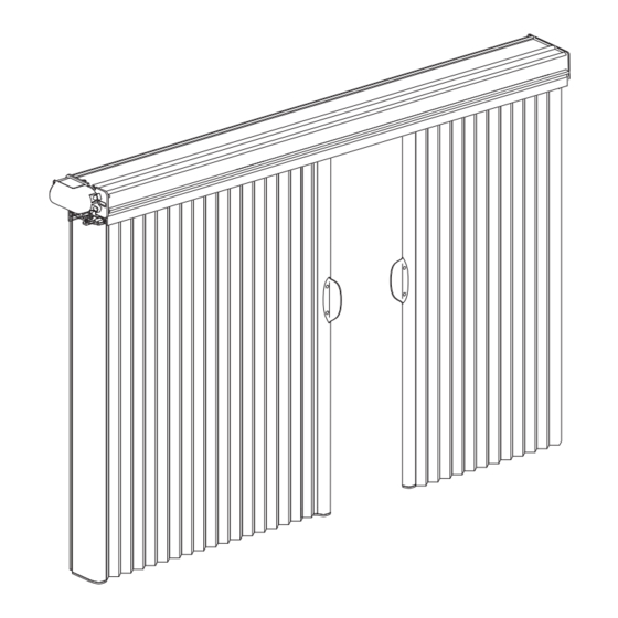
- Page 3 GETTING STARTED Product View Headrail Installation Brackets Manual Control Button Moving Rail Bracket* Battery Wands Cord Tensioners* Tension Ribbon Cable Clip* Ribbon Cable Clip* Cord Motor Gear Box Stationary Fabric Carriers Rail Bracket Stationary Rail Bracket Stationary Handle Rail Moving Rail Optional Outside Mount Hardware: Extension...
- Page 4 GETTING STARTED Thank you for purchasing Smith & Noble® Vertical Cellular shades with Smart Shades. With proper installation, operation, and care, your new shades will provide years of beauty and performance. To get started, unpack the shade and remove all foam/packaging materials. Check that all parts shown on the packing list are included with the order.
- Page 5 ⁄ " – 96" Installation Overview ⁄ " – 139" Installation of Vertical Cellular shades varies based on the shade mounting type, stacking ⁄ " – 168" configuration, and the valance type selected. Use all brackets provided Mounting Types and Window Terminology for each headrail.
- Page 6 INSTALLATION INSTALLATION Stacking Configurations — Split Stack The Vertical Cellular stacking configuration split stack, includes left and right stack configurations. With split stack designs, two ■ fabric panels meet in the center to cover the opening. A split stack configuration consists of two shades, one as a left stack configuration and the other as a right stack configuration. ■...
- Page 7 INSTALLATION INSTALLATION Center the brackets on your marks and mark the screw holes. ■ When using extension brackets, mark two screw holes per bracket. ➤ Drill the screw holes using a ⁄ " drill bit. ■ CAUTION: Use drywall anchors when mounting into drywall. Use the drill bit size recommended by the manufacturer. Attach the installation or extension brackets using the screws provided.
- Page 8 INSTALLATION INSTALLATION If using spacer blocks, first attach the installation bracket to the ⁄ " spacer block before stacking additional spacer blocks or ■ shims together. Insert the legs of the installation bracket into the tabs on the spacer block. ■...
- Page 9 INSTALLATION INSTALLATION Inside/Ceiling Mount Mount the Installation Brackets Install and mount the left stack configuration first. Measure the width of the window, starting at the left side, and use a ■ pencil to mark the center of the window. Hold the headrail of the left stack configuration inside the window opening. Make sure the right-end of the left stack ■...
- Page 10 INSTALLATION INSTALLATION Proceed to mount the right stack headrail. Ensure the right stack headrail is installed as close to the left stack headrail ■ as possible. NOTE: Do not remove the metal endplate from right stack. The left hand metal end plate on the right stack configuration is used to tension both left and right stack configurations after both fabric stacks are installed.
- Page 11 INSTALLATION INSTALLATION Install the Fabric Stack NOTE: The installation procedures that follow are the same for inside and outside mounts, except where indicated. Prepare the Fabric Stack Start with the left fabric stack. Insert the left bracket of the stationary rail bracket into the vertical rail (on the side where the ■...
- Page 12 INSTALLATION INSTALLATION Insert the stationary rail bottom bracket into the bottom of the stationary rail. ■ The bracket fits into grooves at the bottom of the rail. ➤ Insert the bracket with the mounting flanges to the back, away from the fabric stack as shown. Do not seat the bracket; ➤...
- Page 13 INSTALLATION INSTALLATION Review the diagram below to familiarize yourself with where the fabric carrier wheels fit inside the headrail. Note that the ■ headrail is notched to allow insertion of the wheels. Above the notch is a foam block to keep the wheels in place during installation. Compress the foam to install the fabric ➤...
- Page 14 INSTALLATION INSTALLATION Install the stationary rail bracket. ■ Hook the stationary rail bracket to the headrail as illustrated below. ➤ After hooking it to the headrail, you may allow the stationary rail to hang freely. ➤ Stationary Rail Bracket Stationary Rail Position the stationary rail bracket.
- Page 15 INSTALLATION INSTALLATION Outside Mount: Attach the stationary rail bottom bracket. The bracket may be attached to the wall or floor. In most cases, to ■ avoid drilling into the floor it is attached to the wall. Level the stationary rail front to back and side to side. ➤...
- Page 16 INSTALLATION INSTALLATION Secure the stationary rail bracket using the provided small screw. Hold the bracket in ■ place and screw through either of the two holes on the bracket. NOTE: Two #8 x ⁄ " pan head screws are provided; one is a spare. For a split stack design, repeat these steps for the right stack configuration.
- Page 17 INSTALLATION INSTALLATION Cord Tension For an Smart Shades split stack design, set the cord tension of the left stack configuration, before the right stack configuration. ■ Study the cording diagram below. The cords from the left fabric stack are connected to the right-side end plate. (In the ■...
- Page 18 INSTALLATION INSTALLATION Position the cords from the left fabric stack. ■ Place the washer on the end of one cord into the first slot from the rear on the inside of the end plate, as shown. Loop the ➤ cord behind the end plate back through the second slot from the front and pull it taut to seat the washer. Cut the washer from the end of the other cord and tie the cord to the right-most cord tensioner using a square knot.
- Page 19 INSTALLATION INSTALLATION Wrap the cord over the top of the washer to hold it in place and not have it pop out. ■ Repeat the above steps for the cords from the right fabric panel: ■ At the right stack moving rail, unwrap the cord from the orange cord organizer. ➤...
- Page 20 INSTALLATION INSTALLATION Set Cord Tension Remove slack from the cords by moving each cord tensioner away from the end plate ■ it is looped around. If the tensioner must be moved more than one-third of the headrail width away ➤ from its end plate to remove slack, re-tie the knot and trim the excess cord.
- Page 21 INSTALLATION INSTALLATION Tension the cords. ■ IMPORTANT: When the cords are properly tensioned, the moving rails slide easily yet hold their position anywhere along their travel. Slide each cord tensioner along its channel in the headrail until the cord is taut. ➤...
- Page 22 INSTALLATION INSTALLATION Affix the control button to the wall or molding. ■ Peel the backing from the double-sided tape on the rear of the assembly. ➤ Press the control button onto the mounting surface, as shown. ➤ IMPORTANT: Choose a location where the control button will not be obstructed by the valance or side rails, and where the wire will not be pinched.
- Page 23 INSTALLATION INSTALLATION One Battery Wand (If Applicable) NOTE: Refer to this section if your order includes only one battery wand. Plug the single power cable from the motor into the socket on the battery wand. ■ Place the battery wand into the front channel of the headrail. The front lip on the channel holds the wand in position. ■...
- Page 24 INSTALLATION INSTALLATION Insert the Battery Wand into the Battery Mount NOTE: The rechargeable battery wand ships fully charged, so it is ready to install out of the package. Match the direction of the arrow on the underside of the battery wand with the arrow on the battery mount. ■...
- Page 25 INSTALLATION VALANCE INSTALLATION Valance Types Determine the type of valance you are installing with your shade: Aluminum or Alternative Wood Traditional). ■ Valance Clips Aluminum Valance 1¼" Pleat ¾" Pleat Size Corner Size End Cap Return Valance Clips Alternative Wood Traditional Valance Dovetail Brackets 1¼"...
- Page 26 INSTALLATION VALANCE INSTALLATION Aluminum Valance Outside mounts and non-flush inside mounts only: Use the valance corner end caps to attach a return to each end of ■ the valance. Corner End Cap Slide the valance corner end cap onto the valance. Do not hammer the end cap into the valance — the end cap will bend. ➤...
- Page 27 INSTALLATION VALANCE INSTALLATION Wider shades with two-piece valances: Splice the two pieces together using the ■ valance splice. Lay the two pieces face-down on a flat surface with the valance splice between ➤ them, as shown at right. Insert the valance splice into one of the sections. ➤...
- Page 28 INSTALLATION VALANCE INSTALLATION Alternative Wood Traditional Valance Front of Outside mounts and non-flush inside mounts only: Use the valance corner brackets to Notch Valance ■ attach a return to each end of the valance. Valance Fit the tabs on the corner bracket into the notches on the valance and return. Return ➤...
- Page 29 INSTALLATION VALANCE INSTALLATION Attach the valance to the dovetail brackets as shown below. ■ Place the top groove of the valance into the top of the dovetail bracket. ➤ Rotate the valance down and squeeze the dovetail bracket against the valance to snap it in place. ➤...
- Page 30 INSTALLATION OPERATION Operating the Smith & Noble® App and Smart Shades Remote Syncing and Programming Your Remote Activate the remote by pulling both plastic tabs from the back battery compartment. ■ Download the Smith & Noble® App for your smartphone or tablet at getsmithandnobleapp.com. ■...
- Page 31 INSTALLATION OPERATION Resetting the Shade Calibration Reset The calibration reset is used to recalibrate the shade's travel limits. This action is performed in the Smith & Noble® App. NOTE: The Smart Shades Split Stack design requires separate calibration for each stack configuration. Select Calibrate Shade in the Advanced Options section of the Shade Settings menu in the Smith &...
- Page 32 INSTALLATION TROUBLESHOOTING Troubleshooting If your shade is not operating correctly: Review the digital support guide for your control device. ■ Refer to the following troubleshooting procedures for specific solutions for your shade. ■ If questions remain, please contact Smith & Noble® Customer Support at 888-214-2134. Problem The shade will not snap into the installation brackets.
- Page 33 INSTALLATION TROUBLESHOOTING Problem Batteries in the battery wand need to be replaced. Solution Replace the batteries in the battery wand. Squeeze the cap latch to release the cap and remove the cap from the battery wand. Battery Wand Install the batteries according to the instructions on the battery wand label. Press the cap on until it latches.
- Page 34 INSTALLATION TROUBLESHOOTING Problem Rechargeable battery needs recharging. Solution There are two methods for charging the rechargeable battery wand — the dual charging station or the single charger. CAUTION: The rechargeable battery wand can only be charged with these Smith & Noble®-provided charging options.
- Page 35 INSTALLATION TROUBLESHOOTING Problem Rechargeable battery needs recharging (continued). Solution Recharging Via the Single Charger Remove the rechargeable battery wand from the mount, or insert the single charger cable without removing from the shade. Attach the plug adapter to the charger. ■...
- Page 36 INSTALLATION TROUBLESHOOTING Problem The fabric billows out when moving the shade to the stacked (fully open) position. Solution Increase the cord tension. Slide the cord tensioner toward the fabric stack to slightly increase the tension. See Set Cord Tension on page 18. Problem The cord tensioner does not lock into place.
- Page 37 ■ stated in Install the Fabric Stack on page 9. Cleaning Procedures Smith & Noble® Vertical Cellular shades are made of anti-static, dust-resistant fabric which repels dirt and dust. For most Cellular fabrics, the following cleaning options are available. Dusting Regular light dusting with a feather duster is all the cleaning needed in most circumstances.
- Page 38 INSTALLATION CARE Ultrasonic Cleaning CAUTION: Do not ultrasonically clean all room-darkening fabrics. Specify that a mild detergent solution be used. ■ IMPORTANT: Never immerse the headrail into the solution. Dry the shade completely in the lowered (or closed) position. ■ Injection/Extraction Cleaning This type of professional cleaning injects a cleaning solution into the fabric and extracts the dirty solution in the same motion.
- Page 39 INSTALLATION SMITH & NOBLE® SMART SHADES MOTOR DECLARATIONS DECLARATIONS FCC Statement This equipment has been tested and found to comply with the limits for a Class B digital device, pursuant to Part 15 of the FCC Rules. These limits are designed to provide reasonable protection against harmful interference in a residential installation.
- Page 40 INSTALLATION CHILD SAFETY WARNING ADVERTENCIA Window Blind Cord Strangulation Risk Window Blinds with a damaged or loose tension device or retractable cord that fails to fully retract pose a stangulation risk to children. To avoid this potential strangulation risk, consider purchasing cordless products or products with inaccessible cords.
- Page 41 WARRANTY 10-Year Limited Warranty Smith & Noble is proud to extend a 10-year limited warranty on all Smith & Noble Custom Window Covering products. This ® ® is part of our commitment to providing the highest quality products, which has been our continued tradition since 1987. COVERED NOT COVERED by a 10-Year...
Need help?
Do you have a question about the Vertical Cellular Shades and is the answer not in the manual?
Questions and answers