Advertisement
Quick Links
If you have any questions regarding assembly or if parts are missing, DO NOT return this item to
the store where it was purchased. Please call our customer service number and have your
instructions and parts list ready to provide the model name, part name or factory number:
Pacific Standard Time: 8:30 a.m. - 4:30 p.m., Monday - Friday
Or visit our web site 24 hours a day, 7 days a week for product assistance at
THIS INSTRUCTION BOOKLET CONTAINS IMPORTANT SAFETY INFORMATION.
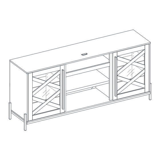
65" TV Stand
Stock # BBAVCL65-FB-2
ADULT ASSEMBLY REQUIRED
www.whalenfurniture.com
Or e-mail your request to parts@whalenfurniture.com
PLEASE READ AND KEEP FOR FUTURE REFERENCE.
Date 2024-06-11
1-866-942-5362
Rev. 0001-A
LOT NUMBER:
DATE PURCHASED:
/
/
Advertisement

Related Manuals for Whalen Adelia BBAVCL65-FB-2


Summary of Contents for Whalen Adelia BBAVCL65-FB-2
- Page 1 LOT NUMBER: DATE PURCHASED: 65” TV Stand Stock # BBAVCL65-FB-2 ADULT ASSEMBLY REQUIRED If you have any questions regarding assembly or if parts are missing, DO NOT return this item to the store where it was purchased. Please call our customer service number and have your instructions and parts list ready to provide the model name, part name or factory number: 1-866-942-5362 Pacific Standard Time: 8:30 a.m.
- Page 2 G E N E R A L I N F O R M A T I O N , T I P S A N D T R I C K S 1. Please read the Assembly Instructions prior to assembling this product. 2.
- Page 3 IMPORTANT Before you begin: Open, identify and count all parts prior to assembly. Lay out parts on a flat and non- abrasive surface. You will need the parts identified on page 4, 5 and 6 of this instruction manuals. NOTE: IT IS VERY IMPORTANT TO USE GLUE WITH DOWELS.
- Page 4 Parts and Hardware List Please read completely through the instructions and verify that all listed parts and hardware are present before beginning assembly. A- Top Panel B- Bottom Panel (Qty. 1) (Qty. 1) C- Left Side Panel D- Right Side Panel E- Left Partition (Qty.
- Page 5 Parts and Hardware List Please read completely through the instructions and verify that all listed parts and hardware are present before beginning assembly. O- Right Back Panel P- Door Q- Handle (Qty. 1) (Qty. 2) (Qty. 2) R- European Hinge S- Reinforcement Tube T- Metal Leg U- Support Leg...
- Page 6 Parts and Hardware List Please read completely through the instructions and verify that all listed parts and hardware are present before beginning assembly. (13) 5/32’’ x 21 mm Handle Bolt (14) Shelf Support (15) Cam Lock Cover (Qty. 4+1 extra) (Qty.
- Page 7 Assembly Instructions ② x 12 NOTE: Please do not fully tighten all bolts/screws until you finish assembling all parts. Once assembled, go back and fully tighten all bolts. This will make it easier during assembly of unit. 1. Securely screw twelve Cam Bolts (2) into the designated small holes on both Top Panel (A) and Bottom Panel (B) using a Phillips screwdriver.
- Page 8 Assembly Instructions ② x 14 2. Securely screw fourteen Cam Bolts (2) into the designated small holes on both Partitions (E and F), Media Shelf Molding (H) and Side Moldings (I) using a Phillips screwdriver.
- Page 9 Assembly Instructions ③ x 12 3. Glue twelve Wood Dowels (3) into the inner holes on both Partitions (E and F). Make sure that you use a small amount of glue with both ends of all dowels. NOTE: It is very important to use a small amount of glue on both ends of dowels and wipe off the excess glue immediately with a damp cloth.
- Page 10 Assembly Instructions ③ x 14 4. Glue fourteen Wood Dowels (3) into the inner holes on both Side Panels (C and D) and the Media Fixed Shelf (G).
- Page 11 Assembly Instructions The outer edges are even ① x 2 5. Orient and position Media Shelf Molding (H) so that the installed cam bolts enter the front edge of the Media Fixed Shelf (G) as shown. 6. Insert two Cam Locks (1) into the large holes in the Media Fixed Shelf (G) making sure that the arrow on the face of cam lock faces out and points towards the entry of the cam bolt.
- Page 12 Assembly Instructions The outer edges are flush The outer edges are flush with each other with each other ① x 8 7. Orient and attach one Side Moldings (I) to the Left Partition (E) respectively by engaging and tightening four Cam Locks (1).Turn the Cam Locks (1) with a Phillips screwdriver until securely locked onto the cam bolts.
- Page 13 Assembly Instructions The molding faces the bottom panel ① x 4 9. Orient and attach the Media Shelf (G) between the assembled Partitions (E and F) by engaging and tightening four Cam Bolts (1) with a Phillips Screwdriver.
- Page 14 Assembly Instructions ⑥ x 4 10. Using the wood dowels as a guide, orient and firmly press the previous assembly to the Bottom Panel (B) as shown. Insert four 50 mm Screws (6) through the mounting holes on the Bottom Panel (B) and securely screw into the Partitions (E and F) with a Phillips screwdriver.
- Page 15 Assembly Instructions The pilot holes for hinge The pilot holes for hinge face inward and are located at front ① x 4 11. Using the wood dowels as a guide, orient and attach the Side Panels (C and D) to the Bottom Panel (B) by engaging and tightening four Cam Locks (1).
- Page 16 Assembly Instructions ⑤ x 3 12. Using the pilot holes as a guide, fasten the Reinforcement Tube (S) to the bottom of Top Panel (A) with three 32 mm Screws (5). Tighten the screws with a Phillips screwdriver.
- Page 17 Assembly Instructions C/D/E/F The Reinforcement Tube ① x 8 13. Orient and attach the installed Top Panel (A) to both Side Panels (C and D) and Partitions (E and F) by engaging eight Cam Locks (1). Turn the Cam Locks (1) with a Phillips screwdriver until securely locked onto the cam bolts.
- Page 18 Assembly Instructions Countersunk holes ⑩ x 4 14. Align and attach the four Metal Legs (T) to the Side Panels (C and D) making sure the mounting hole on the metal bracket overlops the threaded hole properly. Insert the 20 mm Bolts (10) through the counter-sunk holes on both side Paneld (C and D) and screw into the Metal Legs (T).
- Page 19 Assembly Instructions ⑨ x 4 15. Fasten the four Metal Legs (T) to the Bottom Panel (B) with four 15 mm Bolts (9), four Lock Washers (11) and four Flat Washers (12). Tighten the bolts with the Hex Wrench provided.
- Page 20 Assembly Instructions ⑨ x 4 16. Align and attach the two Support Legs (U) to the Bottom Panel (B) by using four 15 mm Bolts (9), four Lock Washers (11) and four Flat Washers (12). Tighten the bolts with the Hex Wrench provided.
- Page 21 Assembly Instructions 90° The adhesive tape faces outward ⑧ x 45 17. Now, go back and tighten all Cam Locks and Screws. Make sure that all the parts are tight and there are no gaps between the pieces. This will help keep the unit square. 18.
- Page 22 Assembly Instructions x 20 20. Ask for assistance to lift the assembled unit upright and position it near the final location. 21. Insert the Shelf Supports (14) into the desired holes in the sides of each compartment. Make sure you place four shelf supports in the same level to assure a level shelf. Tilt and rest the Wood Shelf (J) and Glass Shelves (K) onto the Shelf Supports (14).
- Page 23 Assembly Instructions ⑦ x 8 22. Extend two European Hinges (R) and rest the hinge cups onto the cutouts of each Door (P). Secure the European Hinges (R) in place by using two 15 mm Nickel Screws (7) in each.
- Page 24 Assembly Instructions 23. Attach one Handle (Q) to the front of each Door (P) with two 21 mm Handle Bolts (13).Tighten the bolts with a Phillips Screwdriver.
- Page 25 Assembly Instructions Oval hole Round hole Depth Horizontal Vertical Adjustment Adjustment Adjustment ⑦ x 16 24. Pick up one Door (P) and attach the installed Door Hinges (R) to the Right Side Panel (D), using the pilot holes as a guide. Turn four 15 mm Nickel Screws (7) a few turns through the CENTERS of the oval holes in the hinges.
- Page 26 Assembly Instructions ④ x 1 NOTE: To prevent your TV from tipping, you must install the acrylic TV stopper if you place a flat panel television on the top panel. Otherwise, skip to step 29. 28. Remove the paper backing of Acrylic Stopper (4), then properly align the acrylic stopper into the cutout on the acrylic stopper template on the front of the Top Panel (A).
- Page 27 Assembly Instructions x 20 30. Plug the Cam Lock Covers (15) onto the visible Cams Locks to conceal the cams. 31. Stick the Rubber Bumpers (16) onto the outer front corner of each Door (P) where the Partitions (E and F) are in contact with.
- Page 28 Assembly Instructions Wall Wooden stud Long screw Wall Wall Metal bracket Short screw Connector Wall Floor leveler Steel cable Tools required (not included): Phillips screwdriver, stud finder, measure tape, pencil, power drill and 1/8” drill bit. 32. Ask for assistance to position the assembled unit at the desired location against a wall. If necessary, adjust the installed floor levelers to level the door and correct the tilting.
- Page 29 Assembly Instructions 23" HLA INSERT 23" OPP INSERT NOTE: This unit has been designed to be a mantel which can accommodate a 25" W x 18" H fireplace insert. You can buy our electric fireplace (model # SP23L-FOPP-CR or SP23L-BHLA-CR, sold separately) and combine with this console.
- Page 30 Care and Maintenance Use a soft, clean cloth that will not scratch the surface when dusting. Use of furniture polishes is not necessary. Should you choose to use polishes, test first in an inconspicuous area. Using solvents of any kind on your furniture may damage the finish. ...
- Page 31 Should this product be defective in workmanship or materials or fail under normal use, we will repair or replace it for up to one (1) year from date of purchase. Every Whalen Furniture product is designed to meet your highest expectations. We guarantee that you will immediately see the value of our fine furniture.
Need help?
Do you have a question about the Adelia BBAVCL65-FB-2 and is the answer not in the manual?
Questions and answers