Table of Contents
Advertisement
Quick Links
Advertisement
Table of Contents

Related Manuals for Mastech MS2128


Summary of Contents for Mastech MS2128
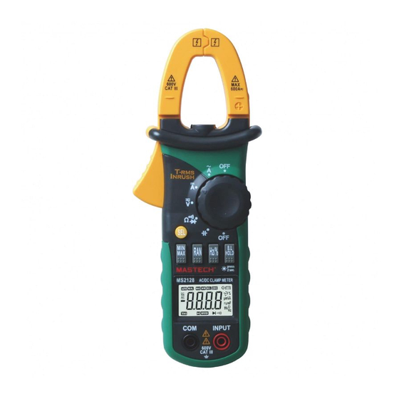
- Page 1 MS2128, MS2108T DIGITAL CLAMP METER OPERATION MANUAL CAT III 600V...
-
Page 2: Table Of Contents
CONTENTS CONTENTS 1. Safety Information......1 4.7 Auto Power Off...........18 1.1 Preliminary ..........1 4.8 Preparing For Measurement ......19 1.2 During use ........2 4.9 Measuring Ac Current ......19 1.3 Symbols..........3 4.10 Measuring Inrush Current ......21 1.4 Maintenance.........3 4.11 Measuring Dc Current ......23 2. -
Page 3: Safety Information
1. Safety Information 1.2 During Use 1.2.1 Use the right input jack, function and range. WARNING 1.2.2 Do not take measurements that exceed the Be extremely careful when using this meter. Improper use of this device protection limit values indicated in the specifications. can result in electric shock or destruction of the meter. -
Page 4: Symbols
1.3 Symbols appears on the display. 1.4.4 Use damp cloth and mild detergent to clean the Note-Important safety information, refer to the meter; do not use abrasives or solvents. instruction manual. 1.4.5 Turn the rotary selector to OFF position to switch Application around and removal from UNINSULATED off the power when the meter is not in use. - Page 5 - The normal function of the product may be disturbed by strong Electro-Magnetic interference. If so, simply reset the product to resume normal operation by following the instruction manual. In case the function could not resume, please use the product in other location.
-
Page 6: Switch, Buttons And Input Jacks
2.2 Switch, Buttons And Input Jacks Alternating current HOLD/B.L Button Direct current - For holding the reading or control backlight S E L Button Diode test - For switching among measuring functions Continuity buzzer RAN Button - For switching between auto and manual ranges. Auto range mode AUTO Hz/% Button... -
Page 7: Specifications
AC voltage: > 13 mV 3.1.4 Operating altitude: max. 2000 meters (7000 ft.) AC current: > 1.3A 3.1.5 Display: LCD 3.1.6 Maximum value display: 6599 digits for MS2128 3.2.2 AC Current 6599 digits for MS2108T Range 3.1.7 Polarity indication: automatic; ‘-’ for negative polarity. - Page 8 3.2.6 AC Voltage 3.2.4 DC Current Range Accuracy Resolution Range Accuracy Resolution ±(1.5% of rdg + 10digits) 660mV 0.1mV 0.01A ±(3.0% of rdg + 10 digits) 6.6V 0.001V 600A 0.1A ±(1.2% of rdg + 5digits) 0.01V - Max. input current: 600A DC ±(1.5% of rdg + 10digits) 600V 0.1V...
- Page 9 3.2.7.2 By V range: 3.2.9 Resistance Range Accuracy Resolution Range Accuracy Resolution 660Hz 0.1Hz 660Ω 0.1Ω ±(1.5% of rdg + 5 digits) 6.6kHz 0.001kHz 6.6kΩ 0.001kΩ 10kHz 0.01kHz ±(1.2% of rdg + 2digits) 66KΩ 0.01kΩ Take it only as referance >10kHz 0.01kHz 660kΩ...
-
Page 10: Operation Instruction
3.2.12 Capacitance capacitance and frequency. 4.2.2 Press the"RAN" button for manual range mode. The For MS2128: range will go up one level at each press and return Range Accuracy Resolution to the lowest level when the highest level is reached. -
Page 11: Switching Functions
Note: 4.6.2 During the back light is working, press the “HOLD/B.L” button for two or more seconds, it 1) During measuring maximum or minimum value, the will be turned off. meter will be set to manual mode automatically. 4.6.3 At the current range, when the back light is 2) During working at frequency or duty measuring switched on, the clamp lighting bulb will be turned function, the meter can't be changed into maximum... -
Page 12: Measuring Ac Current
4) Under the manual range mode, when the scale of the 4.8 Preparating For Measurement value to be measured is unknown beforehand, set the 4.8.1 Switch on the power by turning the rotary selector. range to the highest. If the battery voltage is lower than 3.7V, the “ ”... -
Page 13: Measuring Inrush Current
4.10 Measuring Inrush Current WARNING Beware of Electrocution. Ensure that the test leads are disconnected from the meter before making current clamp measurements. 4.10.1 Set the rotary selector to the A range position. 4.10.2 Press the trigger to open jaw. Fully enclose only one conductor. -
Page 14: Measuring Dc Current
4.11 Measuring DC Current WARNING Beware of Electrocution. Ensure that the test leads are disconnected from the meter before making current clamp measurements. 4.11.1 Set the rotary selector to the A range position. 4.11.2 Auto range mode or manual range mode can be selected by pressing the “RAN”... -
Page 15: Measuring Ac Voltage
4.13 Measuring DC Voltage 4.12 Measuring AC Voltage WARNING WARNING Beware of Electrocution. Pay special attention to Beware of Electrocution. avoid electric shock when measuring high voltage. Pay special attention to avoid electric shock Do not input the voltage which more than 600V DC. when measuring high voltage. - Page 16 4) “ ” means the maximum input voltage is 600V DC. 5) If the test result is more than 610V DC, symbol “O L” will be displayed on LCD and the build-up buzzer will sound.
-
Page 17: Measuring Frequency
4.14 Measuring Frequency 4.14.1 By A range (from current clamp): WARNING Beware of Electrocution. Ensure that the test leads are disconnected from the meter before making current clamp measurements. 4.14.1.1 Set the rotary selector to the A range (A~ or A ) position. - Page 18 4.14.2 By V range: WARNING Beware of Electrocution. Pay special attention to avoid electric shock when measuring high voltage. Do not input the voltage which more than 600V rms AC. 4.14.2.1 Plug the black test lead into the COM jack and the red test lead into the INPUT jack.
-
Page 19: Measuring Duty
4.15 Measuring Duty 4.15.1 By A range ( from current clamp): WARNING Beware of Electrocution. Ensure that the test leads are disconnected from the meter before making current clamp measurements. 4.15.1.1 Set the rotary selector to the A range or A ) position. - Page 20 4.15.2 By V range: WARNING Beware of Electrocution. Pay special attention to avoid electric shock when measuring high voltage. Do not input the voltage which more than 600V rms AC. 4.15.2.1 Plug the black test lead into the COM jack and the red test lead into the INPUT jack.
-
Page 21: Measuring Resistance
4.16 Measuring Resistance WARNING Beware of Electrocution. When measuring in-circuit resistance, make sure that the power of the circuit under test has been turned off and that all capacitors have been fully discharged. 4.16.1 Plug the black test lead into the COM jack and the red test lead into the INPUT jack. -
Page 22: Testing Diode
4.17 Testing Diode 4.17.1 Plug the black test lead into the COM jack and the red test lead into the INPUT jack. 4.17.2 Set the rotary selector to the Ω range position. 4.17.3 Press the "S E L" button to switch to test. -
Page 23: Testing Continuity
50±20Ω, the built-in buzzer will sound. 4.18.6 Take the reading on the LCD. Note: If the test leads are open or the resistance of the circuit is over 660Ω (for MS2128) or 600Ω (for MS2108T) , “O L” will appear on the LCD. -
Page 24: Measuring Capacitance
4.19 Measuring Capacitance WARNING Beware of Electrocution. To avoid electric shock, make sure that the capacitors have been fully discharged before measuring the capacitance of a capacitor. 4.19.1 Plug the black test lead into the COM jack and the red test lead into the INPUT jack. 4.19.2 Set the rotary selector to the range position. -
Page 25: Maintenance
5. Maintenance 5.2 Replacing Test Leads Replace test leads if leads become damaged or worn. 5.1 Replacing The Batteries WARNING WARNING Use meet EN 61010-031 standard, rated CA T III 600V, or To avoid electric shock, make sure that the test better test leads. - Page 26 R-00-05-1584...
Need help?
Do you have a question about the MS2128 and is the answer not in the manual?
Questions and answers