Table of Contents
Advertisement
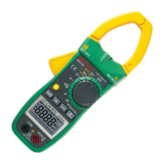
AC/DC DIGITAL CLAMP METER
OPERATION MANUAL
600V CAT III
MS2138
V
FUNC.
RANGE
AC/DC CLAMP METER
AUTO
DC
AC
0
MS2138/R
A
MAX100
AUTO-POWER OFF
OFF
A
100
A
40/400
V
Ω
Press 2 Sec
REL
Hz /%
HOLD
Auto Range
REL
%
Hz
MK
Ω
mnVAF
μ
10
20
30
40
VΩ
COM
CAT III
600V
600 V
CAT III
MAX 600V
www.tools.in.th
ติ ด ต่ อ บริ ษ ั ท นี โอนิ คส์ จํ า กั ด
Tel: 02-077-7602 หรื อ 061-8268939
E-mail: sale@tools.in.th หรื อ sale@neonics.co.th
Advertisement
Table of Contents

Related Manuals for Mastech MS2138/R


Summary of Contents for Mastech MS2138/R
- Page 1 MS2138/R AC/DC DIGITAL CLAMP METER OPERATION MANUAL MAX100 600V CAT III AUTO-POWER OFF MS2138 40/400 Ω FUNC. Press 2 Sec Hz /% RANGE HOLD AC/DC CLAMP METER Auto Range AUTO Ω mnVAF μ www.tools.in.th ติ ด ต่ อ บริ ษ ั ท นี โอนิ คส์ จํ า กั ด...
-
Page 2: Table Of Contents
CONTENTS CONTENTS 1. Safety Information......1 4.5 Switching Functions.........17 4.6 Back Light And Clamp Lighting Bulb..17 1.1 Preliminary..........1 4.7 Auto Power Off.........18 1.2 During Use..........2 4.8 Preparing For Measurement.....18 1.3 Symbols...........3 4.9 Measuring AC Current ......19 1.4 Maintenance..........4 4.10 Measuring DC Current ......20 2. -
Page 4: Symbols
1.2.11 Do not use the meter near explosive gases, 1.4 Maintenance steam or dirt. 1.4.1 Do not attempt to remove the rear case to adjust or 1.2.12 Stop using the meter if any abnormalities or repair the meter. Such actions should only be faults are observed. -
Page 7: Lcd (Liquid-Crystal Display)
3. Specifications Calibration is required once a year, to be carried out at a temperature between 18°C and 28 °C (64°F to 82°F) and relative humidity below 75%. 3.1 General Specifications 3.1.1 Auto range and manual range. 3.1.2 Overrange protection is provided for all ranges. 3.1.3 Maximum voltage between terminals and earth ground: 600V DC or 600V rms AC 3.1.4 Operating altitude: max. -
Page 10: Operation Instruction
measurement function will be cancelled. Disable to 4. Operation Instruction enter REL∆ mode when OL shows. 4.1 Holding Readings 7) No analog section bar function under REL∆ mode. 4.1.1 Press the “HOLD/B.L” button to hold the readings 4.3 Switching Frequency Or Duty while taking measurement and the value on the 4.3.1 During working at the voltage or current ranges, display will be held. -
Page 11: Switching Functions
4.5 SWitching Functions - When the battery voltage is < 3.7V, the symbol “ ” (battery low)will appear on the LCD. When the back 1) FUNC Key is a function selection key that acts with light is on, even if the batter is > 3.7V, the “ ”... -
Page 13: Measuring Ac Voltage
4.11 Measuring AC Voltage 4.12.1 Plug the black test lead into the COM jack and the red test lead into the INPUT jack. 4.12.2 Set the rotary selector to at the range position. WARNING 4.12.3 Connect the test leads to the voltage source or Beware of Electrocution. - Page 15 NOTE: NOTE: 1) Do not put more than one cable into the jaw during 1) If the duty cycle is less than 10%, symbol 'UL' will be test, otherwise incorrect test value might be obtained. displayed on LCD; if the duty cycle is more than 2) If the duty cycle is less than 10%, symbol 'UL' will be 94.9%, symbol 'OL' will be displayed on LCD.
-
Page 16: Measuring Resistance
NOTE: NOTE: 1) If the duty cycle is less than 10%, symbol 'UL' will be 1) When the input is open, 'OL' will appear on the LCD displayed on LCD; if the duty cycle is more than to indicate that the range has been exceeded. 99.9%, symbol 'OL' will be displayed on LCD. -
Page 17: Replacing The Batteries
5.1 Replacing The Batteries WARNING To avoid electric shock, make sure that the test leads have been clearly move away from the circuit under measurement before opening the battery cover of the meter. WARNING Do not mix old and new batteries. Do not mix alkaline, standard (carbon-zinc), or rechargeable (ni-cad, ni-mh, etc) batteries. -
Page 18: Replacing Test Leads
5.2 Replacing Test Leads Replace test leads if leads become damaged or worn. WARNING Use meet EN 61010-031 standard, rated CA T III 600V, or better test leads. 6. Accessories Test Leads: Electric Ratings 1000V 10A 1 pair (set) Operating Manual 1 copy 1.5V AAA Battery 3 piece...
Need help?
Do you have a question about the MS2138/R and is the answer not in the manual?
Questions and answers