
Related Manuals for Mastech MS2109A


Summary of Contents for Mastech MS2109A
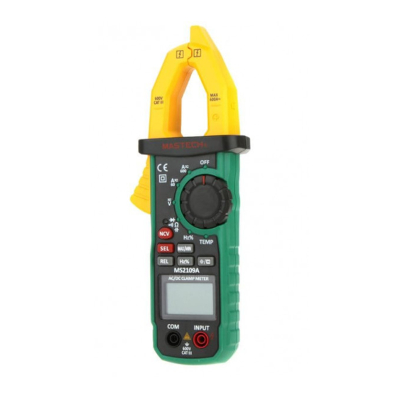
- Page 1 MS2109A AC/DC Clamp Meter User Manual Ω TEMP MAX/MIN MS2109A AC/DC CLAMP METER...
-
Page 2: Table Of Contents
CONTENTS CONTENTS 1. Safety Information….......1 4.6 Relative Measurement and Surge Measurement......17 1.1 Preparation........1 4.7 Back Light and Clamp Head Light..17 1.2 Usage..........2 4.8 Automatic Power-Off ......18 1.3 Signs and Labels........3 4.9 Measurement Preparation....18 1.4 Maintenance........4 4.10 Current Measurement......19 2. Description….........4 4.11 Voltage Measurement......20 2.1 Part Name..........5 4.12 Frequency and... -
Page 3: Safety Information
1. Safety Information 1.1.4 Probe should be in good condition. Before use, please check whether the probe insulation is Warning damaged, whether metal wire is bare. 1.1.5 Use the probe table provided with the meter to Please particularly note that inappropriate use ensure safety. -
Page 4: Maintenance
1.2.10 Don't measure capacitance unless the capacitor 1.4 Maintenance is discharged completely. 1.4.1 Don't try to open the meter bottom case to adjust or 1.2.11 Don't use the meter in explosive gas, vapor or repair. Such operations only can be made by dusty environments. -
Page 5: Lcd Display
(2) NCV indicator (3) Key (4) LCD display (5) Common end jack (6) Resistance, capacitance, voltage, frequency, diode, continuity and temperature input jack (7) Knob (8) Clamp head center position (9) NCV sense position Ω TEMP MAX/MIN MS2109A AC/DC CLAMP METER... - Page 6 2.2 Switch, Button and Input Jack Description 2.3 LCD Display B.L/HOLD button: used for reading hold or back light control MAX/MIN button: used for maximum/minimum measurement function switch. SEL button: used for measuring function switch. NCV button: Non-contact voltage detection switch. REL button: used for entering relative measurement state.
-
Page 7: Specification
3.2.1 AC Current 3. Specifications At least once a year, the meter should be recalibrated Measuring Accuracy Resolution range in temperatures of 18°C ~ 28°C and relative humidity less than 75%. 0.01A ±(2.5% of reading + 6 digits) 3.1 General 600A 0.1A Auto measuring range. - Page 8 Note: 3.2.5.2 Through grade V: In the small voltage measuring range, the probe is not Measuring Accuracy Resolution connected with the circuit to be tested, and the meter range may have fluctuating readings. This is normal and 99.99Hz 0.01Hz caused by the meter's high sensitivity. It does not ±...
- Page 9 3.2.6 Duty Ratio 3.2.8 Circuit Continuity Test Measuring range Resolution Accuracy Measuring Resolution Function range ±(3%+5) 0.1%-99.9% 0.1% If the resistance of circuit to be 0.1Ω 3.2.6.1Through grade A (from clamp head): measured is less than 70Ω, the - Frequency response: 40 ~ 1kHz meter's built-in buzzer may sound.
-
Page 10: Operating Guidance
3.2.11 Temperature 2) If “Hz/%” button is pressed again, the meter will revert to voltage, current measurement state. Measuring Accuracy Resolution range Note: When the meter is in the maximum/minimum value ±(3.0% of reading + +4 digits) -20°C~0°C measurement state, it can't be switched to frequency, ±(1.0% of reading + +3 digits) 1°C~400°C 1°C... -
Page 11: Back Light And Clamp Head Light
4.5 Function Switch Note: 1) In the resistance mode, pressing “SEL” button will When battery voltage is <3.6V, LCD displays “ ” switch among resistance, diode, continuity and (undervoltage) symbol. capacitance detection. But when the user uses the backlight, when the battery 2) In the voltage and current mode, pressing “SEL”... -
Page 12: Current Measurement
4.10 Current Measurement 4.11 Voltage Measurement Warning Warning Electric shock hazard. Electric shock hazard. Remove the probe from the meter before Pay special attention to avoid shock when measuring with current clamp. measuring high voltage. Don't input voltage more than AC 600 V RMS. 1) When measuring switch is placed to position A, the meter is in AC current measurement state. -
Page 13: Frequency And Duty Ratio Measurement
2) Through grade voltage: 4.12 Frequency And Duty Ratio Measurement 1) Clamp head measuring frequency Warning (through grade current): Electric shock hazard. Pay special attention to avoid shock when Warning measuring high voltage. Electric shock hazard. Don't input voltage more than AC 600V RMS. Remove the probe from the meter before measuring with current clamp. -
Page 14: Diode Test
3) Through grade HZ/DUTY: Note: 1) When the input end is open, LCD shows “0L” Warning over-range state. Electric shock hazard. 2) When the resistance to be tested is >1MΩ, the meter Pay special attention to avoid shock when reading will stabliize after a few seconds, which is measuring high voltage. -
Page 15: Capacitance Measurement
4) Connect the probe to the both ends of circuit to 4.17 NCV Measurement be tested. 1) Press NCV key. . 5) If the resistance of circuit to be measured is less 2) Place the NCV sensor zone close to the conductor. than 70Ω, the meter's built-in buzzer may sound. -
Page 16: Maintenance
5. Maintenance 5.1 Replace Battery Warning Before opening the meter battery cover, remove probe from the circuit to be measured to avoid electric shock. 1) When the battery indicator “ ” appears, the battery should be replaced immediately. 2) Unscrew the fastening screw and remove the meter battery cover.
Need help?
Do you have a question about the MS2109A and is the answer not in the manual?
Questions and answers