Table of Contents
Advertisement
Advertisement
Table of Contents

Related Manuals for Mastech MS2115A


Summary of Contents for Mastech MS2115A
- Page 1 MS2115A Digital Clamp Meter Operation Manual...
-
Page 2: Table Of Contents
CONTENTS CONTENTS 1. Safety Information......1 4.5 Function Choice........18 4.6 Relative Measurement 1.1 Preliminary..........1 And Surge Measurement.......19 1.2 Usage............2 4.7 Back Light And Clamp Head Light.....19 1.3 Mark............3 4.8 Automatic Power-Off .......20 1.4 Maintenance..........3 4.9 Measurement Preparation......20 2. Description........4 4.10 Current Measurement......21 2.1 Part Name..........5 4.11 Voltage Measurement......22 2.2 Switch and Button Description....7... -
Page 3: Safety Information
1.1.5 Use the probe table provided with the meter to 1. Safety Information ensure safety. If necessary, replace the probe with another identical probe or one with the same Warning level of performance. Please particularly note that inappropriate use may cause 1.2 Usage shock or damage to the meter when using. -
Page 4: Mark
1.4.4 Clean the meter with damp cloth and mild 1.2.13 Unless the meter bottom case and the battery detergent. Do not use abrasives or solvents. cover are completely fastened completely, do 1.4.5 Power off the meter when the meter is not used. not use the meter. -
Page 5: Part Name
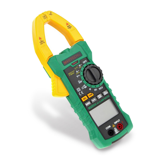
2.1 Part Name (1) Current clamp head: used for current measurement. (2) Clamp head light (3) Panel (4) Trigger (5) Function choice button (FUNC) (6) Relative measurement button (7) Frequency/duty ratio switch button (Hz/%) (8) LCD display (9) Common end jack (10) Resistance, capacitance, voltage, frequency, diode and continuity input jack (11) Maximum/minimum choice button (MAX/MIN) -
Page 6: Lcd Display
2.2 Switch, Button And Input Jack Description AC, DC ALTERNATING CURRENT, direct current B.L/HOLD button: used for reading hold or back Diode, continuity light control Automatic measuring range mode AUTO FUNC button: used for measuring function switch. RANGE button: used for switching manual measuring Maximum measurement state range state. -
Page 7: Specifications
3.2 Technical Indicators 3. Specifications Environment temperature: 23±5°C, relative humidity The meter should be recalibrated under the condition (RH):<75% of 18°C~28°C, relative humidity less than 75% with 3.2.1 True RMS Zero Input Characteristic the period of one year. 3.2.1.1 For measuring non-sinusoidal wave signal, 3.1 General uses true RMS measuring method, which has Automatic measuring range and manual measuring... - Page 8 3.2.3 DC Current Note: In the small voltage measuring range, the probe is not Measuring range Accuracy Resolution connected with the circuit to be tested, and the meter 0.01A may have fluctuating readings, which is normal and ±(2.0% reading + 8 digits) caused by the meter's high sensitivity.
- Page 9 3.2.7 Frequency 3.2.7.3 Through mode HZ/DUTY: 3.2.7.1 Clamp head measuring frequency Measuring range Accuracy Resolution (through mode A): 9.999Hz 0.001Hz Measuring range Resolution Accuracy 99.99Hz 0.01Hz 99.99Hz 0.01Hz ±(1.5% reading + 5 digits) 999.9Hz 0.1Hz 999.9Hz 0.1Hz ±(0.3% reading + 5 digits) 9.999kHz 0.001kHz - Measuring scope: 10Hz~1kHz...
-
Page 10: Operating Guidance
3.2.11 Capacitance 3.2.9 Resistance Measuring range Accuracy Measuring range Accuracy Resolution Resolution 600Ω 0.1Ω 9.999nF 0.001nF 6kΩ 0.001kΩ 99.99nF 0.01nF ±(0.8% reading + 3 digits) 60kΩ 0.01kΩ 999.9nF 0.1nF 9.999µF 0.001µF 600kΩ 0.1kΩ ±(3.0% reading + 5 digits) 99.99µF 0.01µF 6MΩ... -
Page 11: Frequency/Duty Ratio Switch
4.2 Manual Measuring Range 4.4 Maximum/Minimum Measurement Choice RANGE key is automatic/manual measuring range key 1) Press “MAX/MIN” key to enter MAX mode, and to trigger mode. The preset one is automatic measuring always keep measurement maximum value; press range. Press to switch to manual measuring range. “MAX/MIN”... -
Page 12: Back Light And Clamp Head Light
Note: 4.6 REL/INRUSH Measurement 1) REL/INRUSH button is relative value measurement When battery voltage < 7.2V, the LCD displays “ ” button. Operated by tapping this button, it will enter (undervoltage) symbol. When the user uses the relative value measurement mode,. The current backlight, the battery voltage drops below 7.2 V, due to display value can be stored in the memory as high working current. -
Page 13: Current Measurement
4.11 Voltage Measurement 4.10 Current Measurement Warning Warning Electric shock hazard. Electric shock hazard. Remove the probe from the meter before Pay special attention to avoid shock when measuring with current clamp. measuring high voltage. Don't input voltage more than AC750 RMS. 1) Measuring switch is placed to position A. -
Page 14: Frequency And Duty Ratio Measurement
4.12 Frequency And Duty Ratio Measurement 2) In Voltage Measurement Mode: 1) Clamp head measuring frequency Warning (through AC current): Electric shock hazard. Warning Pay special attention to avoid shock when measuring high voltage. Electric shock hazard. Remove the probe from the meter before Don't input voltage more than AC 750 RMS. -
Page 15: Diode Test
Note: (1) Insert black probe to COM jack, insert red probe to NPUT ack. 1) When the input end is open, LCD shows “0L” outrange (2) Transfer switch is placed to position HZ. state. (3) Connect the probe with sinal or both ends of load in 2) When the resistance to be tested>1M, the meter reading parallel for measurement. -
Page 16: Capacitance Measurement
3) Press “FUNC” key to switch to circuit continuity 4.17 Surge Current Measurement measuring state. 4) Connect the probe to the both ends of circuit to be Warning tested for measurement. Electric shock hazard. 5) If the resistance of circuit to be measured is less than Remove the probe from the meter before 50Ω, the meter's built-in buzzer may sound. -
Page 17: Ncv Measurement
4.18 NCV Measurement 1) When the battery symbol “ ” appears, the battery should be replaced immediately. 1) Turn the meter to NCV mode. 2) Unscrew the fastening screw of the battery cover 2) Place the meter top close to the conductor. When and remove the cover. - Page 18 HYS007030...
Need help?
Do you have a question about the MS2115A and is the answer not in the manual?
Questions and answers