Table of Contents
Advertisement
Quick Links
Advertisement
Table of Contents

Related Manuals for Mastech MS2128A


Summary of Contents for Mastech MS2128A
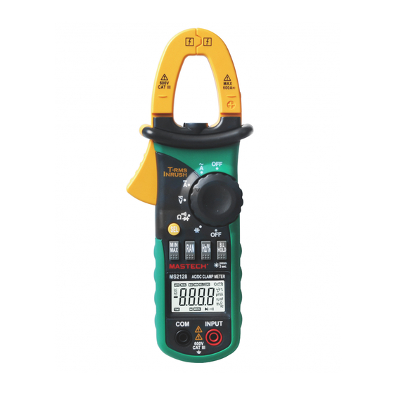
- Page 1 MS2128A DIGITAL CLAMP METER OPERATION MANUAL 400A CAT III 600V...
-
Page 2: Table Of Contents
CONTENTS CONTENTS 1. Safety Information .......1 4.7 Auto Power Off..........18 1.1 Preliminary ..........1 4.8 Preparing For Measurement ......18 1.2 During use ........2 4.9 Measuring Ac Current ........19 1.3 Symbols..........3 4.10 Measuring Dc Current 1.4 Maintenance.........3 ......20 4.11 Measuring Ac Voltage ......22 2. -
Page 3: Safety Information
1.2 During Use 1. Safety Information 1.2.1 Use the right input jack, function and range. WARNING 1.2.2 Do not take measurements that exceed the Be extremely careful when using this meter. Improper use of this device protection limit values indicated in the can result in electric shock or destruction of the meter. -
Page 4: Symbols
1.4.1 Do not attempt to remove the rear case to adjust or 1.2.13 Do not use the meter unless its rear case and repair the meter. Such actions should only be battery cover is securely fastened in its original performed by a technician who fully understands the position. - Page 5 - This meter is equipped with inrush current measuring function. - This meter is equipped with auto zero function (at DCA range). - This meter is equipped with maximum value measuring function. - This meter is equipped with minimum value measuring function. 400A - This meter can measure frequency by clamp.
-
Page 6: Switch, Buttons And Input Jacks
2.2 Switch, Buttons And Input Jacks Alternating current HOLD/B.L Button Direct current - For holding the reading or control backlight S E L Button Diode test - For switching among measuring functions REL Button Continuity buzzer - The key is the relative value measurement. Auto range mode AUTO Hz/% Button... -
Page 7: Specifications
3. Specifications 3.2.1 AC Current Calibration is required once a year, to be carried out at Range Resolution Accuracy a temperature between 18°C and 28°C (64F° to 82F°) 0.01A and relative humidity below 75%. ±(2.0% of rdg + 6 digits) 400A 0.1A 3.1 General Specifications... - Page 8 Note: 3.2.5.2 By ACV range: At small voltage range, unsteady readings will appear Range Accuracy Resolution before the test leads contact the circuit. This is normal 10Hz because the meter is highly sensitive. When the test 0.01Hz leads contact the circuit, the true reading will be shown. ±(1.5% of rdg + 5 digits) 1kHz 0.001kHz...
- Page 9 3.2.6 Duty Cycle 3.2.8 Diode Range Accuracy Range Resolution Resolution Function 1.0% - 99.9% 0.1% ±3.0% Displaying approximate 0.001V for ward voltage of diode 3.2.6.1 By A range ( from current clamp): - Frequency response: 10 ~1kHz - Forward DC current~1mA - Input current range:>...
-
Page 10: Operation Instruction
4. Operation Instruction Disable to enter REL mode when OL shows. 7) No analog section bar function under REL mode. 4.1 Holding Readings 4.3 Switching Frequency Or Duty 4.1.1 Press the “HOLD/B.L” button to hold the readings while taking measurement and the value on the 4.3.1 During working at the voltage or current ranges, display will be held. -
Page 11: Switching Functions
Note: Note: - LED, which requires a larger working current, is the 1) During measuring maximum or minimum value, the main source of back light. Although the meter is meter will be set to manual mode automatically. equipped with a timer set at 15 seconds (i.e. the back 2) During working at frequency or duty measuring light will be off automatically after 30 seconds), function, the meter can't be changed into maximum... -
Page 12: Measuring Ac Current
4.8.3 Turn the rotary selector to the required function 5) “ ” means the maximum input current is and range to be measured. 400A rms AC. 4.8.4 Connect the common test lead first and then the 4.10 Measuring DC Current charged test leads when making connection. -
Page 13: Measuring Ac Voltage
4.11 Measuring AC Voltage WARNING Beware of Electrocution. Pay special attention to avoid electric shock when measuring high voltage. Do not input the voltage which more than750V rms 4.11.1 Plug the black test lead into the COM jack and the red test lead into the INPUT jack. -
Page 14: Measuring Dc Voltage
4.12 Measuring DC Voltage WARNING Beware of Electrocution. Pay special attention to avoid electric shock when measuring high voltage. Do not input the voltage which more than 400A 1000V DC. 4.12.1 Plug the black test lead into the COM jack and the red test lead into the INPUT jack. -
Page 15: Measuring Frequency
4.13 Measuring Frequency 4.13.1 By A range (from current clamp): WARNING Beware of Electrocution. Ensure that the test leads are disconnected from the meter before making current clamp measurements. 4.13.1.1 Set the rotary selector to the A range (A~ or A ) position. - Page 16 4.13.2 By V range: Note: 1) Frequency test range is 10Hz -10kHz. It is possible WARNING to test the frequency which is higher than 10kHz but Beware of Electrocution. the tolerance of the test result Pay special attention to avoid electric shock can not be ensure.
-
Page 17: Measuring Duty
4.14 Measuring Duty 4.14.1 By A range ( from current clamp): WARNING Beware of Electrocution. Ensure that the test leads are disconnected from the meter before making current clamp measurements. 4.14.1.1 Set the rotary selector to the A range position. 4.14.1.2 Press the trigger to open jaw. - Page 18 4.14.2 By V range: WARNING Beware of Electrocution. Pay special attention to avoid electric shock when measuring high voltage. Do not input the voltage which more than 400A 750V rms AC. 4.14.2.1 Plug the black test lead into the COM jack and the red test lead into the INPUT jack.
-
Page 19: Measuring Resistance
4.14.3 By HZ/DUTY range: 4.15.1 Plug the black test lead into the COM jack and the red test lead into the INPUT jack. WARNING Ω 4.15.2 Set the rotary selector to the range position to Beware of Electrocution. make the meter get into Ω... -
Page 20: Testing Diode
4.16 Testing Diode 4.16.1 Plug the black test lead into the COM jack and the red test lead into the INPUT jack. Ω 4.16.2 Set the rotary selector to the range position. 4.16.3 Press the "SEL" button to switch to test. -
Page 21: Testing Continuity
4.17 Testing Continuity WARNING Beware of Electrocution. Make sure that the power of the circuit has been turned off and the capacitors have been fully discharged before testing the 400A continuity of a circuit. 4.17.1 Plug the black test lead into the COM jack and the red test lead into the INPUT jack. -
Page 22: Measuring Capacitance
4.18 Measuring Capacitance WARNING Beware of Electrocution. To avoid electric shock, make sure that the capacitors have been fully discharged 400A before measuring the capacitance of a capacitor. 4.18.1 Plug the black test lead into the COM jack and the red test lead into the INPUT jack. Ω... -
Page 23: Maintenance
5. Maintenance 5.1 Replacing The Batteries WARNING To avoid electric shock, make sure that the test leads have been clearly move away from the circuit under measurement before opening the battery cover of the meter. WARNING Do not mix old and new batteries. Do not mix alkaline, standard (carbon-zinc), or rechargeable (ni-cad, ni-mh, etc) batteries. -
Page 24: Replacing Test Leads
5.2 Replacing Test Leads Replace test leads if leads become damaged or worn. WARNING Use meet EN 61010-031 standard, rated CA T III 600V, or better test leads. WARNING To avoid electric shock,make sure the probes are disconnected from the measured circuit before removingthe rear cover.
Need help?
Do you have a question about the MS2128A and is the answer not in the manual?
Questions and answers