
Related Manuals for LEYBOLD DRYVAC DV 650 ATEX cat. 2i


Summary of Contents for LEYBOLD DRYVAC DV 650 ATEX cat. 2i
- Page 1 DRYVAC DRYVAC DV 650 ATEX cat. 2i Dry Compressing Vacuum Pumps Operating instructions 301062088_Y26_002_C2 Part Numbers 112065V11-1 Original instructions...
- Page 2 Bus Interfaces 301076031 https://4vac.io/32kfrb Trademark credit Leybold and the Leybold logo are trademarks of Leybold GmbH, Bonner Strasse 498, D-50968 Cologne. Disclaimer The content of this manual may change from time to time without notice. We accept no liability for any errors that may appear in this manual nor do we make any expressed or implied warranties regarding the content.
- Page 3 6.5 Connect the purge gas......35 6.5.1 Gas ballast valve......35 301062088_Y26_002_C2 - © Leybold 3...
- Page 4 Maintenance........63 8.1 Leybold Service....... . 63 8.2 Maintenance intervals.
- Page 5 13.2 Wearing parts....... . . 80 14 Legal declarations......81 301062088_Y26_002_C2 - © Leybold 5...
- Page 6 Figure 23. Maintenance of the air filter at the gas ballast valve. 65 Figure 24. Capacitor forming......77 6 301062088_Y26_002_C2 - © Leybold...
- Page 7 NOTICE: Information about properties or instructions for an action which, if ignored, will cause damage to the equipment. We reserve the right to change the design and the stated data. The illustrations are not binding. 301062088_Y26_002_C2 - © Leybold 7...
- Page 8 ▪ The competency of the person shall be relevant to the type of protection used for this pump and accessories. When dealing with an explosive atmosphere, knowledge of the applicable guidelines and standards is mandatory. 8 301062088_Y26_002_C2 - © Leybold...
- Page 9 Risk of injury or damage to the environment. Identifies a source of toxic gases, liquid or material. Warning - Trip hazard Risk of injury. Identifies spilled liquids, trailing cords, pipes and other low-lying objects that may result in slipping, tripping or falling. 301062088_Y26_002_C2 - © Leybold 9...
- Page 10 Risk of injury. Wear appropriate protective goggles when performing the task. Warning - Wear hearing protection Risk of injury. Wear appropriate hearing protection when performing the task. Symbol - Protective earth Identifies an electrical equipment earth (ground) terminal. 10 301062088_Y26_002_C2 - © Leybold...
- Page 11 CAUTION: VACUUM Avoid exposing any part of the human body to the vacuum. CAUTION: AUTOMATIC START UP Connect the pump so that it will not restart automatically after a mains power failure, once the power returns. 301062088_Y26_002_C2 - © Leybold 11...
- Page 12 9. Select the location where the pump is installed so that all controls can be easily accessed. Place the pump only on a floor which is level. It can topple when it is tilted by more than 10 degrees with respect to the vertical axis. 12 301062088_Y26_002_C2 - © Leybold...
- Page 13 5. Observe the manufacturer’s information and operating instructions for the respective frequency converter. 6. The pump must only be operated at the frequency specified for the motor. Use only our frequency converter. 301062088_Y26_002_C2 - © Leybold 13...
- Page 14 5. Operating the pump with less than the specified amount of cooling water will result in excessively high surface temperatures. Moreover, there exists the risk of suffering burns. 14 301062088_Y26_002_C2 - © Leybold...
- Page 15 You can download the safety booklet from our homepage. 2. Before commissioning the pump, make sure that the media which are to be pumped are compatible with each other so as to avoid hazardous situations. 301062088_Y26_002_C2 - © Leybold 15...
- Page 16 II 2/-G Ex eb h IIC T2 Gb/- 5 °C £ Ta £ 50 °C The pump is certified in accordance with the European ATEX Explosion Protection Directive (2014/34/EU). This certification does not cover any 16 301062088_Y26_002_C2 - © Leybold...
- Page 17 24. In other operating modes and with other equipment, higher values must be expected. Make sure that suitable protection measures are taken to protect your hearing. We recommend to wear hearing protectors (earmuffs), if local noise levels exceed mandatory limits. 301062088_Y26_002_C2 - © Leybold 17...
- Page 18 We recommend to fit a non-return discharge valve. 9. The discharge line should be laid so that it slopes down and away from the pump so as to prevent condensed vapours from backstreaming into the pump. 18 301062088_Y26_002_C2 - © Leybold...
- Page 19 17. Maximum cooling water pressure: 7 bar. When exceeded, there is the risk of leaks. Note: Pressures given in bar or mbar are absolute values. If exceptionally a gauge pressure is meant, a “g” is added (bar(g)). 301062088_Y26_002_C2 - © Leybold 19...
- Page 20 3.1 Design The DRYVAC is a dry compressing screw vacuum pump with one screw pumping stage. The DRYVAC DV 650 ATEX cat. 2i is capable of delivering an optimised pumping speed performance also at pressures over 100 mbar. This pump is suited for both cyclic operation, in connection with load lock chambers, for example, and also for continuous operation as a process pump.
- Page 21 - protection by constructional safety “c”, ignition source monitoring “b”, liquid immersion “k” II 2/- G The pump may suck off gases from Zone 1, is however to be installed outside explosion hazard areas. 301062088_Y26_002_C2 - © Leybold 21...
- Page 22 When stored in a humid atmosphere corrosion can occur. ▪ Conversions, manipulations and maintenance work by persons not ▪ authorised by us. Note: Accessories which have not been specified by us may only be used after approval by us. 22 301062088_Y26_002_C2 - © Leybold...
- Page 23 Run regular checks in accordance with these operating instructions. Installation and maintenance only in non-explosion hazard areas. 301062088_Y26_002_C2 - © Leybold 23...
- Page 24 380-460 V ±10% 1)2) Mains voltage Frequency 50/60 Hz ±5% Phases 3-phase Rated motor power 15 kW ±0.8 kW Rated current at 400 V 31 A Motor efficiency class calculated and configured according to EN 6003430 24 301062088_Y26_002_C2 - © Leybold...
- Page 25 Permissible setting pressure Purge gas (at purge 3.0 to 3.5 bar(g)** ±5% gas flow) Permissible supply pressure Purge gas 4.0 to 10.0 bar(g)** ±5% Purge gas flow shaft seal at nominal setting pressure 301062088_Y26_002_C2 - © Leybold 25...
- Page 26 5) Depending on different conditions the gas ballast flow varies. It depends on the inlet pressure. **bar (g): bar (gauge) is the overpressure, i.e. atmospheric pressure = 0 bar (g) 26 301062088_Y26_002_C2 - © Leybold...
- Page 27 Figure 1. Permissible gas inlet temperature as function of the inlet pressure Permissible range: under the curve. For 50 mbar ≤ P ≤ 500 mbar applies: Te= -190 x lg(P ) + 572.8 in °C (mbar) (°C) <50 >500 301062088_Y26_002_C2 - © Leybold 27...
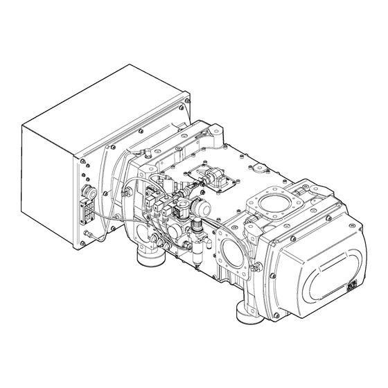
- Page 28 At the installation site, use all four adjustable feet for aligning thereby securing the unit from rolling away and thus taking away the load from the castors. Figure 2. Lifting the DRYVAC Crane eyes (4 off) 28 301062088_Y26_002_C2 - © Leybold...
- Page 29 1) 130 with non-return valve 2) 437 with non-return valve Note: For installation drawings in the DXF format or 3-D installation models in the STEP format, please contact us. Purge gas or gas ballast valves are not shown. 301062088_Y26_002_C2 - © Leybold 29...
- Page 30 Figure: Oil level in the DRYVAC oil glasses. The pumps are supplied filled with synthetic oil. Nothing will have to be refilled. Check the oil levels through all oil level glasses (2 per pumping stage). 30 301062088_Y26_002_C2 - © Leybold...
- Page 31 Support the intake lines. The intake lines must be clean. Connect the intake flange either with intake screen and O-ring or with a centring ring without outer ring. 301062088_Y26_002_C2 - © Leybold 31...
- Page 32 The DRYVAC pumps will be switched off because of overpressure if the abatement system is too small. Connect the exhaust lines to the pump system‘s exhaust connections. Use bellows to eliminate tension in the line. 32 301062088_Y26_002_C2 - © Leybold...
- Page 33 Cooling water data for the pump Materials in the cooling circuit of AISI 304, red brass, brass, EPDM, epoxy the pump paint Feed temperature 5 - 35 °C Feed pressure 2 - 7 bar(g) 301062088_Y26_002_C2 - © Leybold 33...
- Page 34 ≤ 50 mg/l Iron < 0.2 mg/l Manganese < 0.1 mg/l Ammonium < 1.0 mg/l Free chlorine < 0.2 mg/l Note: 8 °dH (degrees German hardness) = 1.4 mmol/l = 10 °e (degrees English hardness) 34 301062088_Y26_002_C2 - © Leybold...
- Page 35 (compressed air or nitrogen) from the valve block is used to actuate the electropneumatic gas ballast valve. The valve needs a pressure of 3.0 bar. The actual ballast gas will generally be ambient air. 301062088_Y26_002_C2 - © Leybold 35...
- Page 36 DRYVAC are equipped with a 0.9 mm nozzle for the exhaust shaft seal and a 2.0 mm nozzle for the inlet shaft seal (for ensuring a sufficient purge during venting). Here the rotor purge is ambient air gas ballast. 36 301062088_Y26_002_C2 - © Leybold...
- Page 37 15 to 30 minutes after stopping the pump. This cleans and dries out the exhaust. ▪ If you want to operate without exhaust shaft seal purge contact our ▪ technical support. ▪ The exhaust purge gas does not reduce the pump performance in any ▪ way. 301062088_Y26_002_C2 - © Leybold 37...
- Page 38 This switch is always installed, but the signal is not controlled by the pump itself (frequency converter). A to be connected Programmable Logic Controller (PLC) or junction box is needed to monitor this signal. 38 301062088_Y26_002_C2 - © Leybold...
- Page 39 Pressure indicator Water SV44 Solenoid Valve Optional flushing Purge gas N 4 ‑ 8 bar PI181 Pressure indicator Nitrogen SV43 Solenoid Valve Optional purge SV42 Solenoid Valve Inlet shaft seal purge* SV41 Solenoid Valve Rotor purge* 301062088_Y26_002_C2 - © Leybold 39...
- Page 40 10 mA. In this case the protective ground conductor must exhibit a cross-section of at least 10 mm or connect a further protective ground conductor having at least the same cross-section as the connection 40 301062088_Y26_002_C2 - © Leybold...
- Page 41 ON (enable) and OFF (disable) the EMC filter. Make sure that the symmetric grounding network is applied when you install the screw in the ON position to enable the built-in EMC filter in compliance with the EMC Directive. Figure 9. Symmetric grounding 301062088_Y26_002_C2 - © Leybold 41...
- Page 42 The control terminal board is equipped with screwless terminals. Always use wires within the specification listed below. For safe wiring it is recommended to use solid wires or flexible wires with ferrules. The stripping length respectively ferrule length should be 8 mm. 42 301062088_Y26_002_C2 - © Leybold...
- Page 43 +1 – d.c. power supply input For connecting a d.c. power supply. For 200 V class: Ground with 100 Ω or less Ground terminal For 400 V class: Ground with 10 Ω or less (2 terminals) 301062088_Y26_002_C2 - © Leybold 43...
- Page 44 DIP switch S4 changes the functionality of analog input A2. When DIP switch S4 is set to P the function is PTC input. When DIP switch S4 is set to M the function of analog input A2 is multi-function input. 44 301062088_Y26_002_C2 - © Leybold...
- Page 45 Remove the cover from the frequency converter. The cover is connected to the PE terminals with a PE cable. Do not interrupt this cable. Use the M32 cable fitting for that purpose. The terminals are designed for 16 mm maximum cable diameter. 301062088_Y26_002_C2 - © Leybold 45...
- Page 46 H1, H2 and HC. The pump’s temperature sensor is connected to A1 and AC. The temperature limiter is connected to S3 and SN. Remount the cover on the frequency converter. 46 301062088_Y26_002_C2 - © Leybold...
- Page 47 The plugs are on the coils on delivery. Table 7. Data for the solenoid coils Parameter Value Voltage 24 V d.c. Power consumption Type of protection (DIN 40050) IP 65 Cable screw connection Pg 9 301062088_Y26_002_C2 - © Leybold 47...
- Page 48 Figure: Permissible gas inlet temperature as function of the inlet pressure. The temperature at the temperature measurement point must then be processed at the RUVAC additionally. After fitting, we recommend running of a leak search. 48 301062088_Y26_002_C2 - © Leybold...
- Page 49 DRYVAC using the four M8 mounting bolts, tightening torque 25 ± 2.5 Nm. Operation Proper operation of the non-return valve is only ensured in connection with clean processes. Operation of the valve needs to be checked regularly depending on the type of application. 301062088_Y26_002_C2 - © Leybold 49...
- Page 50 Installation Figure 16. Non-return valve 112005A15 with swivel joint Figure 17. Side view/sectional view of the non-return valve with swivel joint M8 mounting bolts O-ring Swivel joint Exhaust line DRYVAC 50 301062088_Y26_002_C2 - © Leybold...
- Page 51 301062088_Y26_002_C2 - © Leybold 51...
- Page 52 Some parameters are only taken over after a restart. 7.4.1 LED operator and keys After switching on, the display shows the output frequency in the delivery state (U1-02). The Pt-1000 temperature can be read out in U7-03. 52 301062088_Y26_002_C2 - © Leybold...
- Page 53 On: The drive is in a fault state and the output is stopped. On: The drive is ready to operate the motor. DRV LED light Off: The drive is in the Verify, Setup, Parameter Setting or Auto tuning mode. 301062088_Y26_002_C2 - © Leybold 53...
- Page 54 7.4.2 Power on CAUTION: OPERATION SAFETY Risk of damage to the equipment. The pre-set limiting parameters, in particular the maximum speed, must not be changed. Observe the safety information given in Electrical hazards on page 13. 54 301062088_Y26_002_C2 - © Leybold...
- Page 55 Output frequency (Hz) U1-03 Output current (A) U1-05 Motor speed (Hz) U1-06 Output voltage reference (V a.c.) U1-07 DC bus voltage (V d.c.) U1-08 Output power (kW) U1-09 Torque reference (% of motor rated torque) 301062088_Y26_002_C2 - © Leybold 55...
- Page 56 Output current at previous fault U2-06 Motor speed at previous fault U2-07 Output voltage at previous fault U2-08 DC bus voltage at previous fault U2-09 Output power at previous fault U2-10 Torque reference at previous fault 56 301062088_Y26_002_C2 - © Leybold...
- Page 57 Operation times that belong to the tenth most recent faults U3-20 The faults CPF00, 01, 02, 03, UV1, and UV2 are not recorded in the error log. 7.4.4 Relay option board Figure 19. Relay option board - Connections 301062088_Y26_002_C2 - © Leybold 57...
- Page 58 0 Hz, allowed input range 0 Hz to 120 Hz). Closing of the switch between the digital input S5 and SN will enable the second frequency. The input signal at S5 can be controlled through a timer relay or through the PLC. 58 301062088_Y26_002_C2 - © Leybold...
- Page 59 Make sure that parameter H3‑10 has been set to the default value 0. Connect the control current to terminals A2 and AC. 4 to 20 mA, 4 mA corresponds to 0 Hz, 20 mA corresponds to 120 Hz, linear increase. 301062088_Y26_002_C2 - © Leybold 59...
- Page 60 (PTO) Temperature pump Frequency con‐ 50 °C 60 °C gear side (Pt 1000) verter Motor protection Temperature Motor 130 °C relay and fre‐ quency converter Frequency convert‐ Frequency con‐ 105 °C 110 °C verter temperature 60 301062088_Y26_002_C2 - © Leybold...
- Page 61 Risk of injury or damage to the equipment. If hazardous gases have been pumped previously then observe the safety information given in Hazards caused by materials and substances on page 15 and in the safety booklet. 301062088_Y26_002_C2 - © Leybold 61...
- Page 62 Blow out the cooling water coils with compressed air or nitrogen (maximum 4 bar). Blow into the cooling water inlet port only. Also when storing the pump for longer periods of time the lubricant remains in the pump. 62 301062088_Y26_002_C2 - © Leybold...
- Page 63 Complete overhaul in the service centre Depending on the specific operating (including exhaust pressure function test) conditions maximum 4 years After all maintenance and assembly Check the leakage on the entire pump system work and upon request 301062088_Y26_002_C2 - © Leybold 63...
- Page 64 If it is too high, oil may enter the pumping chamber. Clean the oil-fill port and re-install the plug using a gasket which is in perfect condition. Wipe off any oil residues from the casing. Manually tighten the oil-fill plugs (tightening torque of approximately 10-15 Nm). 64 301062088_Y26_002_C2 - © Leybold...
- Page 65 Figure 23. Maintenance of the air filter at the gas ballast valve Hexagon at the air filter (size 27) Dust cap of the air filter Compressed air gun Locking clip of the air filter Thread at the air filter 301062088_Y26_002_C2 - © Leybold 65...
- Page 66 Figure: Double purge gas module and 24V gas balllast. To replace, unscrew the metal protection basket with cup from the pressure reducer. Unscrew the mounting component and detach the used filter cartridge. Fit the parts using a new filter cartridge again. 66 301062088_Y26_002_C2 - © Leybold...
- Page 67 Lubricant is too thick. Remedy Exchange the lubricant or warm up lubricant and the pump. Cause Motor rotor is defective. Remedy Contact us. Cause Pump has seized: defective impellers, bearings or toothed gears Remedy Contact us. 301062088_Y26_002_C2 - © Leybold 67...
- Page 68 Contact us. Fault Pump is extremely loud Cause Bearing is damaged. Remedy Repair the pump. Cause Thick particle is deposited. Remedy Clean the pump, respectively perform maintenance. Cause Silencer is defective. Remedy Repair the silencer. 68 301062088_Y26_002_C2 - © Leybold...
- Page 69 Pump is losing lubricant (Lubricant leak is apparent) Cause Oil drain plug leaks Remedy Drain lubricant, firmly screw in a new oil drain plug with the gasket, fill in correct lubricant quantity. Cause Oil level glass leaks Remedy Contact us. 301062088_Y26_002_C2 - © Leybold 69...
- Page 70 Contact us. Cause Pump has an internal leak. Remedy Contact us. Cause Piston rings are defective. Remedy Contact us. Fault Pump does not attain its pumping speed Cause Intake screen is clogged. Remedy Clean intake screen. 70 301062088_Y26_002_C2 - © Leybold...
- Page 71 (Publication number Y26/301007788 or YASKAWA GA500 maintenance and troubleshooting manual TOEPYAIGA5001A) for additional error codes which are missing in this manual. The error code information can be found on the frequency converter nameplate. 301062088_Y26_002_C2 - © Leybold 71...
- Page 72 Ground Fault Replace the broken parts. Cable or motor insulation is broken. Reduce the carrier frequen‐ Excessive stray capacitance at fre‐ quency converter output. 72 301062088_Y26_002_C2 - © Leybold...
- Page 73 Check the power supply. ance. Input Phase Make sure that all cables are One of the input phase is lost. Loss properly fixed to the correct Loose wires at the frequency con‐ terminals. verter input. 301062088_Y26_002_C2 - © Leybold 73...
- Page 74 The output frequency is below the Low Speed L_SPd frequency set in P3-01 for the time Detected set in P3-02. Drive was running at or above the C-LiM C-Lim Alarm Final Current Limit for the time P5-04 – P5-03 74 301062088_Y26_002_C2 - © Leybold...
- Page 75 Error message Possible cause Corrective action oPE01 Drive capacity and value set to 02-04 do not match. Contact service oPE02 Parameters were set outside the allowable setting Set the parameters to the prop‐ range. er values. 301062088_Y26_002_C2 - © Leybold 75...
- Page 76 ((H1-02 < 20h) OR (H1-02 > 2Fh)) AND (P1-05 NOT 0) Occurs if MFDI setting in H1-03 is not an external fault setting and P1-06 is unequal to 0. ((H1-03 < 20h) OR (H1-03 > 2Fh)) AND (P1-06 NOT 0) 76 301062088_Y26_002_C2 - © Leybold...
- Page 77 When you operate the drive after you apply the power, wire the drive correctly and check for drive faults, overcurrents, motor vibration, motor speed differences and other defects during operation. Figure 24. Capacitor forming 301062088_Y26_002_C2 - © Leybold 77...
- Page 78 This waste must be disposed of as special waste. European, national and regional regulations concerning waste disposal need to be observed. Waste must only be transported and disposed of by an approved waste disposal vendor. 78 301062088_Y26_002_C2 - © Leybold...
- Page 79 HS1, fill in the electronic HS2 form, print it, sign it, and return the signed copy to us. NOTICE: If we do not receive a completed form, your equipment cannot be serviced. 301062088_Y26_002_C2 - © Leybold 79...
- Page 80 175001A01 For GSD file, manual for the Profibus interface see www.leybold.com/en/media/downloads/ download-software/. 13.1 Ordering information Product Part number DRYVAC DV 650 ATEX cat. 2i 112065V11-1 13.2 Wearing parts Table 17. Wearing parts Accessory Part number Plug screw M16x1.5 (oil fill plug) ES20127105...
- Page 82 EU Declaration of Conformity Leybold GmbH Documentation Officer T: +49(0) 221 347 0 Bonner Strasse 498 documentation@leybold.com D-50968 Köln Germany The product specified and listed below • Product: Screw Vacuum Pump -with motor and frequency converter • Models: DRYVAC DV650 ATEX Cat. 2i •...
- Page 83 This declaration, based on the requirements of the listed Directives and EN ISO/IEC 17050-1, covers all product serial numbers from this date on: 2022-05-23 You must retain the signed legal declaration for future reference This declaration becomes invalid if modifications are made to the product without prior agreement. Andries de Bock –...
- Page 84 ADDITIONAL LEGISLATION AND COMPLIANCE INFORMATION EMC (EU, UK): Class A/B Industrial equipment Caution: This equipment is not intended for use in residential environments and may not provide adequate protection to radio reception in such environments. RoHS (EU, UK): Material Exemption Information This product is compliant with the following Exemptions Annex III: •...
- Page 85 材料成分声明 China Material Content Declaration 有害物质 Hazardous Substances 部件名称 六价铬 多溴联苯 多溴二苯醚 铅 汞 镉 Part name Hexavalent Polybrominated Polybrominated Lead Mercury Cadmium Chromium biphenyls diphenyl ethers (Pb) (Hg) (Cd) (Cr VI) (PBB) (PBDE) 铸铝及铝合金制品 Aluminium alloys 钢合金制品 Steel alloys 铜接头...
- Page 86 This page has been intentionally left blank.
- Page 87 This page has been intentionally left blank.
- Page 88 Leybold GmbH Bonner Strasse 498 50968 Cologne GERMANY +49-(0)221-347-0 info@leybold.com Pioneering products. Passionately applied. www.leybold.com...
Need help?
Do you have a question about the DRYVAC DV 650 ATEX cat. 2i and is the answer not in the manual?
Questions and answers