ZyXEL Communications V500 Series User Manual
Hide thumbs
Also See for V500 Series:
- Specifications (2 pages) ,
- Release note (15 pages) ,
- Quick start manual (16 pages)

Related Manuals for ZyXEL Communications V500 Series


Summary of Contents for ZyXEL Communications V500 Series
- Page 1 V500 Series IP Phone Default Login Details IP Address dhcp User Name admin Password 1234 Firmware Version 1.10 www.zyxel.com Edition 4, 01/2010 www.zyxel.com Copyright © 2009 ZyXEL Communications Corporation...
-
Page 3: About This User's Guide
• Support Disc Refer to the included CD for support documents. • ZyXEL Web Site Please refer to www.zyxel.com for additional support documentation and product certifications. User Guide Feedback Help us help you. Send all User Guide-related comments, questions or suggestions for improvement to the following address, or use e-mail instead. -
Page 4: Document Conventions
Document Conventions Document Conventions Warnings and Notes These are how warnings and notes are shown in this User’s Guide. Warnings tell you about things that could harm you or your device. Note: Notes tell you other important information (for example, other things you may need to configure or helpful tips) or recommendations. - Page 5 Document Conventions Icons Used in Figures Figures in this User’s Guide may use the following generic icons. The V500 icon is not an exact representation of your device. V500 Computer Notebook computer Server DSLAM Firewall Telephone Switch Router V500 Series User’s Guide...
-
Page 6: Safety Warnings
Safety Warnings Safety Warnings For your safety, be sure to read and follow all warning notices and instructions. • Do NOT use this product near water, for example, in a wet basement or near a swimming pool. • Do NOT expose your device to dampness, dust or corrosive liquids. •... - Page 7 Safety Warnings V500 Series User’s Guide...
- Page 8 Safety Warnings V500 Series User’s Guide...
-
Page 9: Table Of Contents
Contents Overview Contents Overview Introduction ..........................29 Introduction ..........................31 Hardware ........................... 35 Tutorials ............................. 45 LCD Screen Menus ........................ 61 Using the LCD Screen ....................... 63 The Phonebook ......................... 71 LCD Menus: Basic Settings ....................... 77 LCD Menus: Advanced ......................103 The Web Configurator ...................... - Page 10 Contents Overview V500 Series User’s Guide...
-
Page 11: Table Of Contents
Table of Contents Table of Contents About This User's Guide ......................3 Document Conventions......................4 Safety Warnings........................6 Contents Overview ........................9 Table of Contents........................11 List of Figures ......................... 19 List of Tables........................... 25 Part I: Introduction................. 29 Chapter 1 Introduction .......................... - Page 12 Table of Contents 2.3.7 Using Voicemail ......................43 2.3.8 Making Conference Calls ................... 43 2.3.9 Transferring a Call ...................... 44 2.3.10 Upgrading the Phone’s Firmware ................44 Chapter 3 Tutorials ........................... 45 3.1 Overview ..........................45 3.2 Setting Up a Network Connection ..................46 3.3 Configuring VoIP Options Automatically ................
- Page 13 Table of Contents Chapter 6 LCD Menus: Basic Settings ....................77 6.1 Overview ..........................77 6.2 Entering the Menu System ....................77 6.3 The System Info Menu ......................78 6.3.1 Firmware Version ....................... 79 6.3.2 IP Address ........................79 6.3.3 VoIP Status ......................... 80 6.4 The Ring Setting Menu ......................
- Page 14 Table of Contents 7.4.11 Codec Priority ......................136 7.4.12 Voicemail Number ....................137 7.4.13 DNS SRV / DNS ..................... 138 7.4.14 Call ID ........................139 7.4.15 NAT Setting ......................139 7.4.16 Backup SIP Server (1 and 2) ................. 147 7.5 The Auto Provision Menus ....................149 7.5.1 Protocol ........................
- Page 15 Table of Contents Chapter 9 Status Screens ........................189 9.1 Overview ..........................189 9.2 Status Screen ........................189 9.2.1 Packet Statistics ....................... 191 9.2.2 VoIP Statistics ......................193 9.2.3 Additional Statistics ....................195 Chapter 10 Network Setup........................197 10.1 Overview .......................... 197 10.1.1 What You Can Do in This Chapter .................
- Page 16 Table of Contents 13.4 Group List Screen ......................232 13.5 Block List Screen ......................233 13.6 DND White List Screen ....................235 Part IV: Maintenance and Troubleshooting ........237 Chapter 14 System ........................... 239 14.1 Overview .......................... 239 14.1.1 What You Can Do in This Chapter ................. 239 14.2 The General Screen .......................
- Page 17 Table of Contents 17.5 Phone Calls and VoIP ...................... 263 Part V: Appendices and Index ............267 Appendix A Product Specifications..................269 Appendix B Setting Up Your Computer’s IP Address ............275 Appendix C Pop-up Windows, JavaScripts and Java Permissions ........305 Appendix D IP Addresses and Subnetting ................
- Page 18 Table of Contents V500 Series User’s Guide...
-
Page 19: List Of Figures
List of Figures List of Figures Figure 1 Internet Telephony Service Provider Application ..............32 Figure 2 IP-PBX Application ........................33 Figure 3 Peer-to-peer Calling ......................... 33 Figure 4 Front Panel Hardware ......................35 Figure 5 Side Panel ..........................38 Figure 6 Rear Panel Hardware ...................... - Page 20 List of Figures Figure 39 LCD Menu: PPPoE Username - Edit ................... 107 Figure 40 LCD Menu: PPPoE Password....................108 Figure 41 LCD Menu: PPPoE Password - Edit ..................109 Figure 42 LCD Menu: Static IP ......................110 Figure 43 LCD Menu: IP Address......................111 Figure 44 LCD Menu: IP Address - Edit ....................
- Page 21 List of Figures Figure 82 LCD Menu: Outbound Proxy Server Address ..............145 Figure 83 LCD Menu: Outbound Proxy Server Address - Edit ............145 Figure 84 LCD Menu: Outbound Proxy Server Port ................146 Figure 85 LCD Menu: Outbound Proxy Server Port - Edit..............147 Figure 86 LCD Menu: Backup SIP Server ...................
- Page 22 List of Figures Figure 125 Network > Mgnt Port ......................200 Figure 126 VoIP > SIP > SIP Settings ....................202 Figure 127 VoIP > SIP > SIP Settings > Advanced ................205 Figure 128 VoIP > SIP > QoS ....................... 209 Figure 129 SIP User Agent ........................
- Page 23 List of Figures Figure 168 Windows Vista: Start Menu ....................280 Figure 169 Windows Vista: Control Panel .................... 280 Figure 170 Windows Vista: Network And Internet ................280 Figure 171 Windows Vista: Network and Sharing Center ..............281 Figure 172 Windows Vista: Network and Sharing Center ..............281 Figure 173 Windows Vista: Local Area Connection Properties ............
- Page 24 List of Figures Figure 211 Subnetting Example: After Subnetting ................318 V500 Series User’s Guide...
-
Page 25: List Of Tables
List of Tables List of Tables Table 1 Models Covered ........................32 Table 2 Front Panel Hardware ....................... 36 Table 3 Side Panel Hardware ........................ 39 Table 4 Rear Panel Hardware ....................... 39 Table 5 Keypad Characters ........................66 Table 6 LCD Menu Overview ......................... 67 Table 7 LCD Status Screen ........................ - Page 26 List of Tables Table 39 LCD Menu: Default Gateway - Edit ..................113 Table 40 LCD Menu: Subnet Mask .......................114 Table 41 LCD Menu: Subnet Mask - Edit .....................115 Table 42 LCD Menu: First / Second DNS .....................115 Table 43 LCD Menu: First / Second DNS - Edit ..................116 Table 44 LCD Menu: SIP Account Configuration ..................117 Table 45 LCD Menu: Display Name .....................118 Table 46 LCD Menu: Display Name - Edit ....................119...
- Page 27 List of Tables Table 82 LCD Menu: Auto Provision Server Address - Edit ..............153 Table 83 LCD Menu: Auto Provision Server Address ................154 Table 84 LCD Menu: Auto Provision Server Port - Edit ............... 155 Table 85 LCD Menu: Auto Provision Expire Time ................156 Table 86 LCD Menu: Auto Provision Expire Time - Edit ..............
- Page 28 List of Tables Table 125 VoIP > Phone Book > Group List ..................232 Table 126 VoIP > Phone Book > Block List ..................233 Table 127 VoIP > Phone Book > DND White List ................235 Table 128 Maintenance > System > General ..................240 Table 129 Maintenance >...
-
Page 29: Introduction
Introduction Introduction (31) Hardware (35) Tutorials (45) -
Page 31: Introduction
H A P T E R Introduction 1.1 Overview This chapter introduces the main applications and features of the V500 Series. It also introduces the ways you can manage your device. Note: The V500 Series includes the V500-T1 and the V501-T1. Illustrations used throughout this book are based on the V500-T1. -
Page 32: Applications
Chapter 1 Introduction At the time of writing, this User’s Guide covers the following models. Table 1 Models Covered V500 IP phone. V501 IP phone with Power over Ethernet (PoE) capability. 1.2 Applications Here are some examples of how you can use your V500. 1.2.1 Make Calls via Internet Telephony Service Provider In a home or small office environment, you can use the V500 to make and receive VoIP telephone calls through an Internet Telephony Service Provider (ITSP). -
Page 33: Make Calls Via Ip-Pbx
Chapter 1 Introduction 1.2.2 Make Calls via IP-PBX If your company has an IP-PBX (Internet Protocol Private Branch Exchange), you can use the V500 to make and receive VoIP telephone calls through it. In this example, you make a call from your V500 (A in the figure), which sends it to the IP-PBX. -
Page 34: Ways To Manage The V500
Chapter 1 Introduction 1.3 Ways to Manage the V500 Use any of the following methods to manage the V500. • Hardware keys. Use the control keys and LCD menus on the V500 for basic configuration. • Web Configurator. This is recommended for everyday management of the V500 using a (supported) web browser. -
Page 35: Hardware
H A P T E R Hardware 2.1 Overview This chapter describes the V500’s physical features, and how to use its phone functions. 2.2 Physical Features This section discusses the V500’s front, side and rear panel hardware features. See your Quick Start Guide for descriptions of how to set up the V500’s hardware and network connections. -
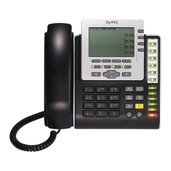
Page 36: Table 2 Front Panel Hardware
Chapter 2 Hardware The following table describes the front panel hardware. Table 2 Front Panel Hardware LABEL DESCRIPTION Handset. LCD (Liquid Crystal Display) screen. Account keys Use these to select the SIP account you want to use. You can configure up to four SIP accounts on the V500. The account keys are independent of the line keys - you can use any SIP account with any line. - Page 37 Chapter 2 Hardware Table 2 Front Panel Hardware (continued) LABEL DESCRIPTION Action keys CONFERENCE Use this to set up a conference call between the V500 and two other phones, or to split a conference call you set up into two separate calls.
-
Page 38: Figure 5 Side Panel
Chapter 2 Hardware Table 2 Front Panel Hardware (continued) LABEL DESCRIPTION Function keys The LEDs (lights) in these keys illuminate when they are active. VOICEMAIL Use this to check your voicemail messages, once the voicemail number is configured on the V500. Each SIP account has its own voicemail number. -
Page 39: Figure 6 Rear Panel Hardware
Chapter 2 Hardware The following table describes the side panel hardware. Table 3 Side Panel Hardware LABEL DESCRIPTION Microphone socket Use this to connect a headset’s microphone jack, or an external microphone. Headphone socket Use this to connect a headset’s earphone jack, headphones, or an external loudspeaker. -
Page 40: The Lcd Screen
Chapter 2 Hardware Table 4 Rear Panel Hardware LABEL DESCRIPTION Power socket Attach the included power adaptor, if you are not using Power over Ethernet (V501-T1 only). See the product specifications appendix for power supply specifications. Note: Use only the power adaptor and cable that came with your V500. -
Page 41: Phone Functions
Chapter 2 Hardware 2.3 Phone Functions This section describes how to use your V500’s basic telephone functions. See Chapter 4 on page 63 for information on the using the V500’s LCD screen menus Chapter 5 on page 71 for information on how to use the V500’s phonebook. 2.3.1 Making a Call Start the call: •... -
Page 42: Ending A Call
Chapter 2 Hardware • Press the SPEAKER key to receive the call using the internal speakerphone. • Press the HEADSET key to receive the call using an external headset. 2.3.3 Ending a Call When you want to end a call, press the HANG UP key. Alternatively, do one of the following: •... -
Page 43: Using Voicemail
Chapter 2 Hardware Press the HOLD key once to place a call on hold. Press it a second time to return to the call. While a call is on hold, you can make a call on another line (press another line key) and then return to the call on hold. 2.3.7 Using Voicemail Once you have configured your SIP account’s voicemail number on the V500, you can press the VOICEMAIL key to check your messages. -
Page 44: Transferring A Call
IP PBX to which the V500 is connected to automatically check your phone’s existing firmware and compare it to the firmware on an official ZyXEL server. If your firmware’s version number does not match, the IP PBX will then initiate the upgrade process: When the IP PBX is ready to process your phone, it rings you while the phone is on the hook. -
Page 45: Tutorials
H A P T E R Tutorials 3.1 Overview These tutorials show you how to perform numerous functions of the V500. Even though they make certain basic assumptions that may not match your actual configuration environment, the foundation provided here should be sufficient to get you up and running as quickly as possible. -
Page 46: Setting Up A Network Connection
Chapter 3 Tutorials 3.2 Setting Up a Network Connection The V500 is an IP phone. As such, you need to have an active network connection for it to work. This allows it to connect to a voice server. To establish a network connection: For PPoE: Open the >... - Page 47 Chapter 3 Tutorials For DHCP: Open the > Advanced > Network Setting screen, select the MENU DHCP (Off) menu option and set it to On. Network Setting 1 PPPoE (Off) 2 Static IP (Off) 3 DHCP (On) Select Back All: Once you have configured all the appropriate network settings on your V500, open the >...
-
Page 48: Configuring Voip Options Automatically
Chapter 3 Tutorials 3.3 Configuring VoIP Options Automatically Once you have established a network connection, the next thing you must do is configure the V500 so that it can connect to a voice server. If your voice server uses auto provisioning, then that server can automatically upload all the required VoIP configuration data directly to your phone;... -
Page 49: Configuring Voip Options Manually
Chapter 3 Tutorials 3.3.1 Configuring VoIP Options Manually If your phone network does not use or support automatic configuration through auto provisioning, then you must configure the V500’s voice server settings yourself. The essential settings you need to establish a VoIP connection are: SETTING TUTORIAL VALUE NOTES... - Page 50 Chapter 3 Tutorials To configure your VoIP settings: Open the > Advanced > SIP Configuration screen and select one of four MENU available account slots. (You may be prompted to enter the administrator password. The default is “1234”.) SIP Configuration 1 VoIP 1 Config.
-
Page 51: Placing A Call
Chapter 3 Tutorials 3.4 Placing a Call Placing a phone call on your V500 is as easy as with any other phone, although you have a greater variety of options available to you with this one. First and foremost you can have up to 4 separate phone lines with their own VoIP numbers all on the same unit so choosing which line to use may seem like a daunting task (it’s not, but if this is your first experience with the V500 it is easy to understand how it could be). - Page 52 Chapter 3 Tutorials Press the Account Key that corresponds to the phone number you want to use to dial out. If you only have one VoIP account set up then you can skip this step as that account is always chosen automatically by default. The speaker activates, presenting you with a dial tone.
-
Page 53: Receiving An Incoming Call On A 2Nd Line
Chapter 3 Tutorials 3.4.1 Receiving an Incoming Call on a 2nd Line Now that you know how to place calls, we’re going to show you how to retrieve an incoming call on a second VoIP number if you’re already talking on a first one. For example, let’s say you’re talking to Jasmine on Line 1 (using VoIP account ‘1001’, from our previous examples) and Sebastian calls in on Line 2 (or VoIP account ‘1002’). - Page 54 Chapter 3 Tutorials When a new call comes in on a different line while you’re in the middle of the first call, the V500 notifies you on screen by displaying Ringing in the lower right corner. The first available Line key also starts blinking; in this case, it is Line 2 because Line 1 is already being used to speak with Jasmine.
-
Page 55: Making A Conference Call
Chapter 3 Tutorials 3.5 Making a Conference Call A conference call consists of three connected phones (including yours) participating in the same conversion simultaneously. To make a conference call: Dial the number of the first person in your conference call. When your party answers, press the button. - Page 56 Chapter 3 Tutorials Next, dial the third party’s number. When they answer, press the the button again to begin the three way CONFERENCE conference call. Your V500 LCD screen should look similar to this: 3:30 2008-11-21 Line 1 To: 1001 Jasmine 00:03:10 Line 2 To:...
-
Page 57: Retrieving Voice Mail
Chapter 3 Tutorials 3.6 Retrieving Voice Mail When you dial a number and the person at the other end does not pick up, you are prompted to leave a voice mail or dial another extension. This tutorial shows you how to listen to any voice mail messages that you might have received. To retrieve a voice mail message: When you have a new voice mail message waiting, three indicators notify you: •... - Page 58 Chapter 3 Tutorials • A moment later, the Main screen displays the Voice Mail Notification screen: 3:30 2008-11-21 You Got: 1 Voice Mail Select Back To retrieve your voice mail messages, press the LED button. This takes VOICE MAIL you directly to the audio prompt. Simply follow the instructions as they are presented to you.
-
Page 59: Setting The Time On Your V500
Chapter 3 Tutorials 3.7 Setting the Time on Your V500 By default, your phone’s time is set automatically using an external time server. However, you can set the time manually as well. This tutorial takes you directly to the V500’s operating system: the Web Configurator. To set the time on your V500: First, we need to get your phone’s IP address. - Page 60 Chapter 3 Tutorials Open the Maintenance > System > Time Setting screen, and configure your V500’s time settings as you see fit. V500 Series User’s Guide...
-
Page 61: Lcd Screen Menus
LCD Screen Menus Using the LCD Screen (63) The Phonebook (71) LCD Menus: Basic Settings (77) LCD Menus: Advanced (103) -
Page 63: Using The Lcd Screen
H A P T E R Using the LCD Screen 4.1 Overview This chapter shows how to use and configure the V500 by means of the LCD screen menu system. Note: For a complete overview of the V500’s navigation and keypad buttons, please refer to Section 1 of the Quick Start Guide. -
Page 64: The Keypad
Chapter 4 Using the LCD Screen The following table describes the navigation pad features. FEATURE DESCRIPTION Softkeys These keys’ functions depend on the screen currently displayed on the LCD screen. A word or symbol displayed on the LCD screen above a softkey shows its current function. Menu Press this to display the V500’s configuration menu. -
Page 65: Working With The Lcd Menus
Chapter 4 Using the LCD Screen 4.4 Working with the LCD Menus Once you are familiar with the navigation and keypads, it is actually quite easy to move about within the LCD menu system. As described in previous sections, the navigation pad gives you the freedom to open menus and make menu selections while the keypad allows you to configure the specific features that require your direct input. -
Page 66: Entering Numbers, Letters And Symbols
Chapter 4 Using the LCD Screen 4.4.2 Entering Numbers, Letters and Symbols When you enter information into the V500 (when setting up a phonebook entry, for example) you may need to enter different kinds of characters. The alphanumeric keypad has four input modes: •... -
Page 67: Enabling And Disabling Features
Chapter 4 Using the LCD Screen 4.5 Enabling and Disabling Features Some of the features on the V500 must be enabled before they can be used or, in some cases, configured. These features display on the LCD screen with (On) or (Off) next to their names, indicating their current status. - Page 68 Chapter 4 Using the LCD Screen Table 6 LCD Menu Overview (continued) MENU DESCRIPTION Ring Setting Default / Family / Business / Use these menus to set the V500 to ring Friend / Others differently when an incoming call is from a member of a group you set up in the Phonebook >...
- Page 69 Chapter 4 Using the LCD Screen Table 6 LCD Menu Overview (continued) MENU DESCRIPTION Advanced Network PPPoE Use this menu to configure your PPPoE Setting Setting username and password, if provided by your Internet Service Provider or network administrator. Static IP Use this menu to give your V500 an IP address.
-
Page 70: The Lcd Status Screen
When you first turn on the V500 or make a call, the status screen displays. The status screen is divided into four main sections, as shown below. Figure 9 LCD Status Screen 03:30 2009-06-21 No Reg ZyXEL Unused Unused Unused The following table describes the labels in this figure. -
Page 71: The Phonebook
H A P T E R The Phonebook 5.1 Overview Use the V500’s phonebook to store the names and phone numbers of your contacts. You can either add phonebook entries yourself (up to 200), or they can be supplied via auto provisioning (up to 1000). The following sections describe how to add, edit, delete and use phonebook entries. - Page 72 Chapter 5 The Phonebook The Contact List screen displays. Private Phonebook 1. Andrew 912345 2. Bob 923456 3. Connie 934567 Edit Back Note: You can also access the Contact List screen by pressing the MENU key and selecting Phonebook > Contact List. Press Add.
- Page 73 Chapter 5 The Phonebook • If you want to add this contact to a caller group select Group. The Caller Group screen displays. Caller Group 1 Default 2 Family 3 Business 4 Friend 5 Others Select Cancel • Select the group to which you want to add this contact. When the contact calls you, the V500 uses the ring tone you configure in the Ring Setting menu.
-
Page 74: Edit A Phonebook Entry
Chapter 5 The Phonebook • If you want to use speed dial to call this number, select Speed Dial. The Speed Dial screen appears. Speed Dial Key 1 Key 2 Key 3 Key 4 Key 5 Key 6 Key 7 Key 8 Select Cancel... -
Page 75: Delete A Phonebook Entry
Chapter 5 The Phonebook Scroll to the field you want to edit. If you want to change the Group or Assign Account settings, or to toggle the Block field on or off, press Select. Press Save when you have finished editing the entry. 5.4 Delete a Phonebook Entry Take the following steps to remove a contact’s entry from the phonebook. -
Page 76: Call A Phonebook Contact
Chapter 5 The Phonebook 5.5 Call a Phonebook Contact In order to call a number you previously entered into the V500’s phonebook, press the PHONEBOOK key and choose an available phonebook (such as Private). Private Phonebook 1. Andrew 912345 2. Bob 923456 3. -
Page 77: Lcd Menus: Basic Settings
H A P T E R LCD Menus: Basic Settings 6.1 Overview This chapter discusses how to set up your V500 using the internal configuration menus. 6.2 Entering the Menu System Press the MENU key on the V500’s front panel to enter the menu system. The Menu Setting screen displays as shown below. -
Page 78: The System Info Menu
Chapter 6 LCD Menus: Basic Settings 6.3 The System Info Menu The System Info menu allows you to quickly check some of your V500’s settings. These settings are read-only. Press MENU > System Info. The following screen displays. Figure 11 LCD Menu: System Info System Name 1 Firmware Version 2 IP Address... -
Page 79: Firmware Version
Chapter 6 LCD Menus: Basic Settings 6.3.1 Firmware Version Use these menus to check your V500’s firmware version. Select Firmware Version in the System Info menu. The following screen displays. Figure 12 LCD Menu: Firmware Version Firmware Version V1.10(AOX.2)da1 Back You can upload new firmware using the web configurator. -
Page 80: Voip Status
Chapter 6 LCD Menus: Basic Settings The following table describes the labels in this screen. Table 9 LCD Menu: IP Address LABEL DESCRIPTION IP Address This is the IP address currently assigned to the V500. IP Subnet Mask This is the subnet mask currently configured on the V500. Gateway This is the IP address of the device on the network your V500 uses to access the Internet. -
Page 81: The Ring Setting Menu
Chapter 6 LCD Menus: Basic Settings The following table describes the labels in this screen. Table 10 LCD Menu: VoIP Status LABEL DESCRIPTION SIP 1 ~ 4 These are the VoIP accounts configured on the V500. An account must be registered to make and receive calls, and must be active before the V500 tries to register it. -
Page 82: The Ring Type Menu
Chapter 6 LCD Menus: Basic Settings The following table describes the labels in this screen. Table 11 LCD Menu: Ring Setting LABEL DESCRIPTION Default Select this to change the ringtone the V500 uses when an incoming call is not from a member of any group. Family, Business, Select this to change the ringtone the V500 uses when an Friend, Others... -
Page 83: The Volume Setting Menu
Chapter 6 LCD Menus: Basic Settings 6.5 The Volume Setting Menu Use these menus to set the loudness of the V500’s audio equipment. Figure 17 LCD Menu: Volume Setting Volume Setting 1 Speaker Volume 2 Phone Volume 3 Ring Volume 4 Headset Volume Select Back... -
Page 84: Volume Screen
Chapter 6 LCD Menus: Basic Settings 6.5.1 Volume Screen When you select one of the options in the Volume Setting menu, a screen similar to the following displays. This example uses the Speaker Volume screen. Figure 18 LCD Menu: Volume Screen Speaker Volume Apply Down... -
Page 85: The Call Preference Menu
Chapter 6 LCD Menus: Basic Settings 6.6 The Call Preference Menu Use these menus to allow or prohibit incoming calls that do not carry caller ID information, and to set up call forwarding. Select Call Preference. The following screen displays. Figure 19 LCD Menu: Call Preference Call Preference 1 Recv. -
Page 86: Call Forward
Chapter 6 LCD Menus: Basic Settings 6.6.1 Call Forward Use these menus to set up and activate different kinds of call redirection for incoming calls. Enable and select Call Preference > Call Forward. The following screen displays. Note: The Call Forward (On/Off) option in the previous screen (Section 6.6 on page 85) must be set to On for these configuration settings to be functional and, in the case of Forward Number, editable. -
Page 87: Figure 21 Lcd Menu: Conditional Forward
Chapter 6 LCD Menus: Basic Settings 6.6.1.1 Conditional Forward Use this menu to specify the conditions under which you want calls to be redirected. Enable and select Call Preference > Call Forward > Conditional Forward. The following screen displays. Figure 21 LCD Menu: Conditional Forward Conditional Forward 1 On Busy Forward (Off) 2 No Answer Forward (On) -
Page 88: Figure 22 Lcd Menu: Forward Number
Chapter 6 LCD Menus: Basic Settings 6.6.1.2 Forward Number Use this menu to set the phone number to which calls are redirected. Note: This phone number is used for unconditional and conditional call forwarding, but not for specific call forwarding. Select Call Preference >... -
Page 89: Figure 23 Lcd Menu: Forward Number - Edit
Chapter 6 LCD Menus: Basic Settings 6.6.1.2.1 Forward Number - Edit Press Edit in the Forward Number screen to change the phone number to which the V500 forwards calls. The following screen displays. Figure 23 LCD Menu: Forward Number - Edit Call Forward Number Current:... -
Page 90: Figure 24 Lcd Menu: Specific Forward Entry Table
Chapter 6 LCD Menus: Basic Settings You can configure up to ten specific forwarding entries. Figure 24 LCD Menu: Specific Forward Entry Table Specific Forward Entry 1 (Off) Entry 2 (Off) Entry 3 (Off) Entry 4 (Off) Entry 5 (Off) Entry 6 (Off) Entry 7 (Off) Entry 8 (Off) -
Page 91: Figure 25 Lcd Menu: Specific Forward Entry
Chapter 6 LCD Menus: Basic Settings 6.6.1.3.1 Specific Forward Entry Use the specific forward entries to specify the incoming caller’s number, the number to which you want the call to be redirected, and the conditions under which it should be redirected. When you enable and select an Entry in the Specific Forward Entry Table menu, the following menu displays. - Page 92 Chapter 6 LCD Menus: Basic Settings Take the following steps to configure a specific forward entry. Select Incoming Call Number in the Specific Forward Entry menu. The following screen displays. Incoming Call Number Current: 1234 Edit Back Press Edit. Enter the new incoming call number and press Save. The Specific Forward Entry menu displays.
- Page 93 Chapter 6 LCD Menus: Basic Settings Select Condition. The following screen displays. Condition 1 Unconditional (On) 2 Busy Forward (Off) 3 NoAnswer Forward (Off) 4 DND Active (Off) Back Select the conditions under which you want calls from this number to be redirected.
-
Page 94: The Phonebook Menu
Chapter 6 LCD Menus: Basic Settings 6.7 The Phonebook Menu Use the phonebook to set up a list of your contacts. You can also assign your contacts to groups, block calls from them, allow them to call you even when you have DND (Do Not Disturb) turned on, and set up speed dial entries. -
Page 95: Caller Group
Chapter 6 LCD Menus: Basic Settings Note: You can also press the PHONEBOOK key on the V500 to access the Contact List. Chapter 5 on page 71 for information on using the Contact List. 6.7.2 Caller Group Use these menus to see which of your contacts belong to the predefined groups on the V500. -
Page 96: Figure 28 Lcd Menu: Caller Group List
Chapter 6 LCD Menus: Basic Settings 6.7.2.1 The Caller Group List Select one of the options in the Caller Group menu to display a list of the contacts who belong to that group. This example shows the list of Business contacts. Figure 28 LCD Menu: Caller Group List Business 1. -
Page 97: Block List
Chapter 6 LCD Menus: Basic Settings 6.7.3 Block List This shows the phone numbers that are barred from calling you. When you are called from a number on the Block List, the V500 does not ring. Note: You can either configure the numbers you want to block in this screen (press Add) or set an entry in the Contact List to be blocked. -
Page 98: Dnd White List
Chapter 6 LCD Menus: Basic Settings 6.7.4 DND White List This shows which of your contacts can call you when DND (Do Not Disturb) is turned on. When someone on the DND White List calls, the V500 rings whether DND is on or not. Note: Only entries in your Contact List can be in the DND White List. -
Page 99: Using Speed Dial
Chapter 6 LCD Menus: Basic Settings 6.7.5 The Speed Dial Menu This menu allows you to set up one-touch calling. You can map a phone number to an alphanumeric keypad key (0 to 9) and then use that keypad key to call the phone number (press and hold the key for one second or longer). -
Page 100: Figure 32 Lcd Menu: Speed Dial - Edit
Chapter 6 LCD Menus: Basic Settings 6.7.5.2 The Speed Dial - Edit Screen The Speed Dial - Edit screen allows you to add and change the phone numbers that are mapped onto the alphanumeric keys. Press Edit in the Speed Dial screen. -
Page 101: The Advanced Setting Menu
Chapter 6 LCD Menus: Basic Settings 6.7.5.2.1 Speed Dial - Edit Phonebook Take the following steps to map a phonebook entry to a speed dial key Press Pbook in the Speed Dial screen. The following screen displays. Figure 33 LCD Menu: Speed Dial - Edit Phonebook Phonebook 1 Public 2 Private... -
Page 102: The System Restart Menu
Chapter 6 LCD Menus: Basic Settings 6.9 The System Restart Menu Use this screen to restart the V500 without turning the power off. Select System Restart. The following screen displays. Figure 34 LCD Menu: System Restart System Restart Restart System ? The following table describes the labels in this screen. -
Page 103: Lcd Menus: Advanced
H A P T E R LCD Menus: Advanced 7.1 Overview This chapter discusses using the V500’s Advanced LCD menus. 7.1.1 What You Can Do in This Chapter • Set up your V500’s IP address - see Section 7.3.2 on page 110 Section 7.3.3 on page 116. -
Page 104: The Advanced Setting Menu
Chapter 7 LCD Menus: Advanced 7.2 The Advanced Setting Menu Select Advanced Setting. The following screen displays. Figure 35 LCD Menu: Advanced Setting Advanced Setting 1 Network Setting 2 SIP Configuration 3 Auto Provision (On) 4 Programmable Key 5 Display Adjusting 6 Call Feature Mode 7 Language Support 8 Flexworker Mode... -
Page 105: The Pppoe Menu
Chapter 7 LCD Menus: Advanced The following table describes the labels in this screen. Table 29 LCD Menu: Network Setting LABEL DESCRIPTION PPPoE Use this to configure the V500’s PPPoE username and password, if it is a PPPoE client. Static IP Use this if you have an IP address to use for the V500. -
Page 106: Figure 38 Lcd Menu: Pppoe Username
Chapter 7 LCD Menus: Advanced Table 30 LCD Menu: PPPoE LABEL DESCRIPTION Select Press this to choose the highlighted field in the menu. Back Press this to return to the previous screen. 7.3.1.1 PPPoE Username Enable and select Advanced Setting > Network Setting > PPPoE > Username. -
Page 107: Figure 39 Lcd Menu: Pppoe Username - Edit
Chapter 7 LCD Menus: Advanced 7.3.1.1.1 PPPoE Username - Edit If you press Edit in the PPPoE Username screen, the following screen displays. Figure 39 LCD Menu: PPPoE Username - Edit PPPoE Username Uppercase Current: New: Save <- Back The following table describes the labels in this screen. Table 32 LCD Menu: PPPoE Username - Edit LABEL DESCRIPTION... -
Page 108: Figure 40 Lcd Menu: Pppoe Password
Chapter 7 LCD Menus: Advanced 7.3.1.2 PPPoE Password Enable and select Advanced Setting > Network Setting > PPPoE > Password. The following screen displays. Figure 40 LCD Menu: PPPoE Password PPPoE Password Current: **** Edit Back The following table describes the labels in this screen. Table 33 LCD Menu: PPPoE Password LABEL DESCRIPTION... -
Page 109: Figure 41 Lcd Menu: Pppoe Password - Edit
Chapter 7 LCD Menus: Advanced 7.3.1.2.1 PPPoE Password - Edit Press Edit in the PPPoE > PPPoE Password screen. The following screen displays. Figure 41 LCD Menu: PPPoE Password - Edit PPPoE Password Number Current: **** New: Confirm: Save <- Back The following table describes the labels in this screen. -
Page 110: Static Ip
Chapter 7 LCD Menus: Advanced 7.3.2 Static IP Use this menu to manually configure your V500’s IP address, subnet mask and gateway settings. Enter the settings exactly as your ISP or network administrator gave them to you. Enable and select Advanced Setting > Network Setting > Static IP. The following screen displays. -
Page 111: Figure 43 Lcd Menu: Ip Address
Chapter 7 LCD Menus: Advanced 7.3.2.1 IP Address Enable and select Advanced Setting > Network Setting > Static IP > IP Address. The following screen displays. Figure 43 LCD Menu: IP Address Static IP Current: 192.168.1.1 Edit Back The following table describes the labels in this screen. Table 36 LCD Menu: IP Address LABEL DESCRIPTION... -
Page 112: Figure 45 Lcd Menu: Default Gateway
Chapter 7 LCD Menus: Advanced The following table describes the labels in this screen. Table 37 LCD Menu: IP Address - Edit LABEL DESCRIPTION Current This is the static IP address currently configured on the V500. Enter the static IP address you want the V500 to use in dotted decimal notation. -
Page 113: Figure 46 Lcd Menu: Default Gateway - Edit
Chapter 7 LCD Menus: Advanced 7.3.2.2.1 Default Gateway - Edit Press Edit in the Default Gateway screen. The following screen displays. Figure 46 LCD Menu: Default Gateway - Edit Static Gateway Number Current: 192.168.1.254 New: Save <- Cancel The following table describes the labels in this screen. Table 39 LCD Menu: Default Gateway - Edit LABEL DESCRIPTION... -
Page 114: Figure 47 Lcd Menu: Subnet Mask
Chapter 7 LCD Menus: Advanced 7.3.2.3 Subnet Mask Enable and select Advanced Setting > Network Setting > Static IP > Subnet Mask. The following screen displays. Figure 47 LCD Menu: Subnet Mask Subnet Mask Current: 255.255.255.0 Edit Back The following table describes the labels in this screen. Table 40 LCD Menu: Subnet Mask LABEL DESCRIPTION... -
Page 115: Figure 49 Lcd Menu: First / Second Dns
Chapter 7 LCD Menus: Advanced The following table describes the labels in this screen. Table 41 LCD Menu: Subnet Mask - Edit LABEL DESCRIPTION Current This is the subnet mask your V500 is configured to use. Enter the new subnet mask in dotted decimal notation. Mode Cycle through different character input modes using the # key. -
Page 116: Dhcp
Chapter 7 LCD Menus: Advanced 7.3.2.4.1 First / Second DNS - Edit Press Edit in the 1st DNS or 2nd DNS screen. A screen similar to the following displays (this example uses the 1st DNS screen). Figure 50 LCD Menu: First / Second DNS - Edit 1st DNS Number Current: 0.0.0.0... -
Page 117: The Sip Configuration Menus
Chapter 7 LCD Menus: Advanced 7.4 The SIP Configuration Menus Use these menus to set up your V500 to use your existing Voice over Internet (VoIP) account(s). You can configure up to four VoIP accounts on the V500. Note: Once you have configured the fields in these menus with the correct information, the V500 must register with the SIP server. -
Page 118: Display Name
Chapter 7 LCD Menus: Advanced Table 44 LCD Menu: SIP Account Configuration (continued) Section 7.4.8 on page 131 SIP Service Domain Section 7.4.9 on page 133 SIP Auth ID Section 7.4.10 on page 135 Auth Password Section 7.4.11 on page 136 Codec Priority Section 7.4.12 on page 137 Voicemail Number... -
Page 119: Sip Number
Chapter 7 LCD Menus: Advanced 7.4.1.1 Account Name - Edit Press Edit in the Account Name screen. The following screen displays. Figure 53 LCD Menu: Display Name - Edit Account Name Number Current: New: Save <- Back The following table describes the labels in this screen. Table 46 LCD Menu: Display Name - Edit LABEL DESCRIPTION... -
Page 120: Figure 54 Lcd Menu: Sip Number
Chapter 7 LCD Menus: Advanced Select Advanced Settings > SIP Configuration > SIP (1 ~ 4) Configuration > SIP Number. The following screen displays. Figure 54 LCD Menu: SIP Number SIP Number Current: 1234 Edit Back The following table describes the labels in this screen. Table 47 LCD Menu: SIP Number LABEL DESCRIPTION... -
Page 121: Sip Local Port
Chapter 7 LCD Menus: Advanced The following table describes the labels in this screen. Table 48 LCD Menu: SIP Number - Edit LABEL DESCRIPTION Current This shows the SIP number already configured for this account. Enter the SIP number you want this account to use. Mode Cycle through different character input modes using the # key. -
Page 122: Figure 57 Lcd Menu: Sip Local Port - Edit
Chapter 7 LCD Menus: Advanced 7.4.3.1 SIP Local Port - Edit Press Edit in the SIP Local Port screen. The following screen displays. Figure 57 LCD Menu: SIP Local Port - Edit SIP Local Port Number Current: 5060 New: Save <- Back The following table describes the labels in this screen. -
Page 123: Sip Server Address
Chapter 7 LCD Menus: Advanced 7.4.4 SIP Server Address Use this menu to see and edit the IP address of the SIP server for this account. Select Advanced Setting > SIP Configuration > SIP (1 ~ 4) Configuration > SIP Server Addr. The following screen displays. Figure 58 LCD Menu: SIP Server Address SIP Server Addr Current: 0.0.0.0... -
Page 124: Figure 59 Lcd Menu: Sip Server Address - Edit
Chapter 7 LCD Menus: Advanced 7.4.4.1 SIP Server Address - Edit Press Edit in the SIP Server Addr screen. The following screen displays. Figure 59 LCD Menu: SIP Server Address - Edit SIP Server Addr Number Current: 0.0.0.0 New: Save <- Back The following table describes the labels in this screen. -
Page 125: Sip Server Port
Chapter 7 LCD Menus: Advanced 7.4.5 SIP Server Port Use this screen to see and edit the port on the this account’s SIP server used for SIP calls. Select Advanced Setting > SIP Configuration > SIP (1 ~ 4) Configuration > SIP Server Port. The following screen displays. Figure 60 LCD Menu: SIP Server Port SIP Server Port Current: 5060... -
Page 126: Figure 61 Lcd Menu: Sip Server Port - Edit
Chapter 7 LCD Menus: Advanced 7.4.5.1 SIP Server Port - Edit Press Edit in the SIP Server Port screen. The following screen displays. Figure 61 LCD Menu: SIP Server Port - Edit SIP Server Port Number Current: 5060 New: Save <- Back The following table describes the labels in this screen. -
Page 127: Sip Register Server
Chapter 7 LCD Menus: Advanced 7.4.6 SIP Register Server Use this menu to see and edit the IP address of the server your service provider uses to register the V500 for this account (also known as a registrar server). Select Advanced Setting > SIP Configuration > SIP (1 ~ 4) Configuration >... -
Page 128: Figure 63 Lcd Menu: Sip Register Server Address - Edit
Chapter 7 LCD Menus: Advanced 7.4.6.1 SIP Register Server - Edit Press Edit in the SIP Register Server screen. The following screen displays. Figure 63 LCD Menu: SIP Register Server Address - Edit SIP Register Server Number Current: 0.0.0.0 New: Save <- Back... -
Page 129: Sip Register Port
Chapter 7 LCD Menus: Advanced 7.4.7 SIP Register Port Use this screen to see and edit the listening port on the SIP registrar server for calls from this account. Select Advanced Setting > SIP Configuration > SIP (1 ~ 4) Configuration > SIP Register Port. The following screen displays. Figure 64 LCD Menu: SIP Register Port SIP Register Port Current: 5060... -
Page 130: Figure 65 Lcd Menu: Sip Register Port - Edit
Chapter 7 LCD Menus: Advanced 7.4.7.1 SIP Register Port - Edit Press Edit in the SIP Register Port screen. The following screen displays. Figure 65 LCD Menu: SIP Register Port - Edit SIP Register Port Number Current: 5060 New: Save <- Back The following table describes the labels in this screen. -
Page 131: Sip Service Domain
Chapter 7 LCD Menus: Advanced 7.4.8 SIP Service Domain Use this to see and edit the SIP service domain configured for this SIP account. The SIP service domain of the VoIP service provider (the company that lets you make phonecalls over the Internet) is the domain name in a SIP URI. For example, if the SIP address is “1122334455@voip-provider.com”, then “voip- provider.com”... -
Page 132: Figure 67 Lcd Menu: Sip Service Domain - Edit
Chapter 7 LCD Menus: Advanced 7.4.8.1 SIP Service Domain - Edit Press Edit in the SIP Service Domain screen. The following screen displays. Figure 67 LCD Menu: SIP Service Domain - Edit SIP Service Domain Number Current: New: Save <- Back The following table describes the labels in this screen. -
Page 133: Sip Authentication Id
Chapter 7 LCD Menus: Advanced 7.4.9 SIP Authentication ID A SIP account’s authentication ID is its username. Select Advanced Setting > SIP Configuration > SIP (1 ~ 4) Configuration > SIP Auth ID to see and edit the SIP authentication ID for this SIP account. The following screen displays. Figure 68 LCD Menu: SIP Authentication ID SIP Auth ID Current:... -
Page 134: Figure 69 Lcd Menu: Sip Authentication Id - Edit
Chapter 7 LCD Menus: Advanced 7.4.9.1 SIP Authentication ID - Edit Press Edit in the SIP Auth ID screen. The following screen displays. Figure 69 LCD Menu: SIP Authentication ID - Edit SIP Auth ID Number Current: New: Save <- Back The following table describes the labels in this screen. -
Page 135: Authentication Password
Chapter 7 LCD Menus: Advanced 7.4.10 Authentication Password Use this screen to see and edit the password for this SIP account. Select Advanced Setting > SIP Configuration > SIP (1 ~ 4) Configuration > Auth Password. The following screen displays. Figure 70 LCD Menu: Authentication Password Auth Password Current: ****... -
Page 136: Codec Priority
Chapter 7 LCD Menus: Advanced The following table describes the labels in this screen. Table 64 LCD Menu: Authentication Password - Edit LABEL DESCRIPTION Current This shows the SIP authentication ID already configured for this account. Each asterisk (*) represents one character of the password configured on the V500. -
Page 137: Voicemail Number
Chapter 7 LCD Menus: Advanced Press Change to cycle through the available codecs. Press Apply to save your changes and return to the previous menu, or press Back to return to the previous menu without saving. See the section on voice coding and decoding in the web configurator section for information on each of the codecs. -
Page 138: Dns Srv / Dns
7.4.13 DNS SRV / DNS DNS (Domain Name System) allows your V500 to resolve a domain name (like www.zyxel.com) to an IP address (like 203.160.232.7). If you do not use a DNS server, you cannot use domain names (when configuring a SIP account, for example);... -
Page 139: Call Id
Chapter 7 LCD Menus: Advanced 7.4.14 Call ID Turn this On to have the V500 send caller ID for outgoing calls. The person you call can tell who is calling. Turn this Off if you want the V500 not to send caller ID. 7.4.15 NAT Setting Use these menus to configure NAT (Network Address Translation) on the V500. -
Page 140: Figure 76 Lcd Menu: Stun
Chapter 7 LCD Menus: Advanced 7.4.15.1 STUN Use this menu to have the V500 get NAT information automatically from a STUN server. Enable and select Advanced Setting > SIP Configuration > SIP (1 ~ 4) Configuration > NAT Setting > STUN. The following screen displays. Figure 76 LCD Menu: STUN STUN 1 Server Addr... -
Page 141: Figure 77 Lcd Menu: Stun Server Address
Chapter 7 LCD Menus: Advanced 7.4.15.1.1 STUN Server Address Use this menu to see or edit the IP address of the STUN server you want to use. Enable and select Advanced Setting > SIP Configuration > SIP (1 ~ 4) Configuration >... -
Page 142: Figure 79 Lcd Menu: Stun Server Port
Chapter 7 LCD Menus: Advanced The following table describes the labels in this screen. Table 69 LCD Menu: STUN Server Address - Edit LABEL DESCRIPTION Current This shows the STUN server address already configured for this account. Enter the new STUN server address for this account. Mode Cycle through different character input modes using the # key. -
Page 143: Figure 80 Lcd Menu: Stun Server Port - Edit
Chapter 7 LCD Menus: Advanced Press Edit in the STUN Server Port screen. The following screen displays. Figure 80 LCD Menu: STUN Server Port - Edit Server Port Number Current: 3478 New: Save <- Back The following table describes the labels in this screen. Table 71 LCD Menu: STUN Server Port - Edit LABEL DESCRIPTION... -
Page 144: Figure 81 Lcd Menu: Outbound Proxy
Chapter 7 LCD Menus: Advanced 7.4.15.2 Outbound Proxy Use this menu to have the V500 use an outbound proxy server. Enable and select Advanced Setting > SIP Configuration > SIP (1 ~ 4) Configuration > NAT Setting > Outbound Proxy. The following screen displays. Figure 81 LCD Menu: Outbound Proxy Outbound Proxy 1 Server Addr... -
Page 145: Figure 82 Lcd Menu: Outbound Proxy Server Address
Chapter 7 LCD Menus: Advanced 4) Configuration > NAT Setting > Outbound Proxy > Server Addr. The following screen displays. Figure 82 LCD Menu: Outbound Proxy Server Address Outbound Server Address Current: Edit Back The following table describes the labels in this screen. Table 73 LCD Menu: Outbound Proxy Server Address LABEL DESCRIPTION... -
Page 146: Figure 84 Lcd Menu: Outbound Proxy Server Port
Chapter 7 LCD Menus: Advanced The following table describes the labels in this screen. Table 74 LCD Menu: Outbound Proxy Server Address - Edit LABEL DESCRIPTION Current This shows the Outbound Proxy server address already configured for this account. Enter the new Outbound Proxy server address for this account. Mode Cycle through different character input modes using the # key. -
Page 147: Backup Sip Server (1 And 2)
Chapter 7 LCD Menus: Advanced Press Edit in the Outbound Proxy Server Port screen. The following screen displays. Figure 85 LCD Menu: Outbound Proxy Server Port - Edit Server Port Number Current:5060 New: Save <- Back The following table describes the labels in this screen. Table 76 LCD Menu: Outbound Proxy Server Port - Edit LABEL DESCRIPTION... -
Page 148: Figure 86 Lcd Menu: Backup Sip Server
Chapter 7 LCD Menus: Advanced Select Advanced Setting > SIP Configuration > SIP (1 ~ 4) Configuration > Backup SIP Server. The following screen displays. Figure 86 LCD Menu: Backup SIP Server Backup SIP Server 1 1st Backup SIP Server (Off) 2 2nd Backup SIP Server (Off) Select Back... -
Page 149: The Auto Provision Menus
Chapter 7 LCD Menus: Advanced The following table describes the labels in this screen. Table 77 LCD Menu: First / Second Backup SIP Server LABEL DESCRIPTION SIP Server Address This is the IP address of the backup SIP server. See Section 7.4.4 on page 123 for information on how to configure this. -
Page 150: Protocol
Chapter 7 LCD Menus: Advanced The following table describes the labels in this screen. Table 78 LCD Menu: Auto Provision LABEL DESCRIPTION Protocol Select this to see or edit the protocol the V500 uses to request and receive auto-provisioning files. Server Address Select this to see or edit the auto provisioning server’s IP address. -
Page 151: Figure 90 Lcd Menu: Auto Provision Protocol - Edit
Chapter 7 LCD Menus: Advanced The following table describes the labels in this screen. Table 79 LCD Menu: Auto Provision Protocol LABEL DESCRIPTION Current This shows the auto-provision protocol already configured on the V500. Edit Press this to change the auto-provision protocol. Note: The V500 must use the same protocol as the auto- provisioning server. -
Page 152: Auto-Provisioning Server Address
Chapter 7 LCD Menus: Advanced 7.5.2 Auto-provisioning Server Address Use this screen to see or edit the IP address of the auto-provisioning server from which the V500 gets the auto-provisioning file. Enable and select Advanced Setting > Auto Provision > Server Address. The following screen displays. -
Page 153: Figure 92 Lcd Menu: Auto Provision Server Address - Edit
Chapter 7 LCD Menus: Advanced 7.5.2.1 Auto-provisioning Server Address - Edit Press Edit in the Server Address screen. The following screen displays. Figure 92 LCD Menu: Auto Provision Server Address - Edit Server Address Number Current: New: Save <- Back The following table describes the labels in this screen. -
Page 154: Auto-Provisioning Server Port
Chapter 7 LCD Menus: Advanced 7.5.3 Auto-provisioning Server Port Use this screen to see or edit the listening port of the auto-provisioning server from which the V500 gets the auto-provisioning file. Enable and select Advanced Setting > Auto Provision > Port. The following screen displays. -
Page 155: Expire Time
Chapter 7 LCD Menus: Advanced 7.5.3.1 Auto-provisioning Server Port - Edit Press Edit in the Server Port screen. The following screen displays. Figure 94 LCD Menu: Auto Provision Server Port - Edit Server Port Number Current: New: Save <- Back The following table describes the labels in this screen. -
Page 156: Figure 95 Lcd Menu: Auto Provision Expire Time
Chapter 7 LCD Menus: Advanced Enable and select Advanced Setting > Auto Provision > Expire Time. The following screen displays. Figure 95 LCD Menu: Auto Provision Expire Time Expire Time Current Timeout (sec): 3600 Edit Back The following table describes the labels in this screen. Table 85 LCD Menu: Auto Provision Expire Time LABEL DESCRIPTION... -
Page 157: Retry Time
Chapter 7 LCD Menus: Advanced The following table describes the labels in this screen. Table 86 LCD Menu: Auto Provision Expire Time - Edit LABEL DESCRIPTION Current Timeout This shows the expire time already configured on the V500. New Timeout Enter the new expire time. -
Page 158: Programmable Key
Chapter 7 LCD Menus: Advanced 7.5.5.1 Retry Time - Edit Press Edit in the Retry Time screen. The following screen displays. Figure 98 LCD Menu: Auto Provision Retry Time - Edit Retry Time Number Current Timeout (sec): 1800 New Timeout (sec): Save <- Back... -
Page 159: Figure 99 Lcd Menu: Programmable Feature Key
Chapter 7 LCD Menus: Advanced Select Advanced Setting > Programmable Key. The following screen displays. Figure 99 LCD Menu: Programmable Feature Key Programmable Key Number Key 1: Key 2: Key 3: Key 4: Key 5: Key 6: Apply <- Back The following table describes the labels in this screen. -
Page 160: Display Adjusting
Chapter 7 LCD Menus: Advanced 7.7 Display Adjusting Use this menu to change the way the LCD screen displays. You can change the screen’s brightness and contrast levels. Select Advanced Setting > Display Adjusting. The following screen displays. Figure 100 LCD Menu: Display Adjusting Display Adjusting 1 Contrast 2 Brightness... -
Page 161: Contrast
Chapter 7 LCD Menus: Advanced 7.7.1 Contrast Use this menu to change the LCD screen’s contrast (the difference between the text shade and the background shade). Select Contrast in the Display Adjusting menu. The following screen displays. Figure 101 LCD Menu: Contrast Contrast Apply Down... -
Page 162: Brightness
Chapter 7 LCD Menus: Advanced 7.7.2 Brightness Use this menu to change the LCD screen’s brightness. Select Brightness in the Display Adjusting menu. The following screen displays. Figure 102 LCD Menu: Brightness Brightness Apply Down Cancel The following table describes the labels in this screen. Table 92 LCD Menu: Brightness LABEL DESCRIPTION... -
Page 163: Call Feature Mode
Chapter 7 LCD Menus: Advanced 7.8 Call Feature Mode Use this menu to switch between local mode and PBX mode. Select Advanced Setting > Call Feature Mode. The following screen displays. Figure 103 LCD Menu: Call Feature Mode Call Feature Mode 1 Local Mode (Off) 2 PBX Mode (On) Select... -
Page 164: Call Feature Mode
Chapter 7 LCD Menus: Advanced 7.8.1 Call Feature Mode Select PBX Mode in the Advanced > Call Feature Mode screen. The following screen displays. The call feature items listed here are automatically configured using auto- provisioning. Each one displays a corresponding key combination that you can press on the keypad to engage it. -
Page 165: Table 94 Lcd Menu: Call Feature Mode
Chapter 7 LCD Menus: Advanced The following table describes the labels in this screen. Table 94 LCD Menu: Call Feature Mode LABEL DESCRIPTION AgentLogin This is code used to login an agent account. When this used, the agent must enter their account ID and password. If you enter this code a second time, it logs you out of the system. -
Page 166: Language Support
Chapter 7 LCD Menus: Advanced Table 94 LCD Menu: Call Feature Mode LABEL DESCRIPTION DND2IVR This is the code to forward an incoming call to voice mail system when the call was forwarded to this extension and this extension is set Do Not Disturb. DND2Off This is the code used to turn the Do Not Disturb 2 feature off for this extension. -
Page 167: Flexworker Mode
Chapter 7 LCD Menus: Advanced The following table describes the labels in this screen. Table 95 LCD Menu: Language Support LABEL DESCRIPTION English ~ Russian Select a language for the LCD menus. Apply Press this to save your settings. Back Press this to return to the previous screen. -
Page 168: Using Flexworker Mode
7.10.1 Using Flexworker Mode The Flexworker system lets a person use any IP phone connected to a Flexworker- compatible IP PBX (such as the ZyXEL X6004) and retain the following account- specific settings: call log, personal phonebook, speed dial, programmable key, call forward, block list, DND white list, SIP account, account name, user name, password, voice mail number, and advanced SIP settings. - Page 169 Chapter 7 LCD Menus: Advanced This displays the Login screen, as shown next. Flexworker Login User Name: CaseyJones Extension Number: 1234 Password: **** Apply <- Back Enter your User Name, Extension Number, and Password then press Apply. The Back key returns to the previous screen without retaining any information you may have entered here while the <- (arrow) key lets you backspace to delete a mistakenly entered character.
-
Page 170: Clock Alarm Setting
Chapter 7 LCD Menus: Advanced 7.11 Clock Alarm Setting Use the menu to configure the V500’s clock alarm feature. Select Advanced Setting > Clock Alarm Setting. The following screen displays. Note: The three alarms must have different configurations. You cannot have two or three identical alarms. -
Page 171: Clock Alarm Configuration
Chapter 7 LCD Menus: Advanced 7.11.1 Clock Alarm Configuration Use the menu to configure the V500’s clock alarm feature. Figure 108 LCD Menu: Clock Alarm Configuration Clock Alarm Configuration 1 Time 2 Message 3 Day 4 Ring Select Back The following table describes the labels in this screen. Table 98 LCD Menu: Clock Alarm Configuration LABEL DESCRIPTION... -
Page 172: Clock Alarm Time
Chapter 7 LCD Menus: Advanced 7.11.2 Clock Alarm Time Select Time in the Clock Alarm Configuration screen. The following screen displays. Figure 109 LCD Menu: Clock Alarm Time Clock Alarm Time Current: 12:30 Edit Back The following table describes the labels in this screen. Table 99 LCD Menu: Clock Alarm Time LABEL DESCRIPTION... -
Page 173: Figure 110 Lcd Menu: Clock Alarm Time - Edit
Chapter 7 LCD Menus: Advanced 7.11.2.1 Clock Alarm Time - Edit Press Edit in the Clock Alarm Time screen. The following screen displays. Figure 110 LCD Menu: Clock Alarm Time - Edit Clock Alarm Time Number Current: 12:30 New:_ Save <- Back The following table describes the labels in this screen. -
Page 174: Clock Alarm Message
Chapter 7 LCD Menus: Advanced 7.11.3 Clock Alarm Message Select Message in the Clock Alarm Configuration screen. The following screen displays. Figure 111 LCD Menu: Clock Alarm Message Clock Alarm Message Current: Edit Back The following table describes the labels in this screen. Table 101 LCD Menu: Clock Alarm Message LABEL DESCRIPTION... -
Page 175: Figure 112 Lcd Menu: Clock Alarm Message - Edit
Chapter 7 LCD Menus: Advanced 7.11.3.1 Clock Alarm Message - Edit Press Edit in the Clock Alarm Message screen. The following screen displays. Figure 112 LCD Menu: Clock Alarm Message - Edit Clock Alarm Message Number Current: Alarm1 New:_ Save <- Back The following table describes the labels in this screen. -
Page 176: Clock Alarm Day
Chapter 7 LCD Menus: Advanced 7.11.4 Clock Alarm Day Select Day in the Clock Alarm Configuration screen. The following screen displays. Figure 113 LCD Menu: Clock Alarm Day Clock Alarm Day Everyday (on) Sunday (on) Monday (on) Tuesday (on) Wednesday (on) Thursday (on) Friday... -
Page 177: Clock Alarm Ring
Chapter 7 LCD Menus: Advanced 7.11.5 Clock Alarm Ring Select Ring in the Clock Alarm Configuration screen. The following screen displays. Figure 114 LCD Menu: Clock Alarm Ring Clock Alarm Ring Chirp 0 Chirp 1 Chirp 2 Chirp 3 Chirp 4 Chirp 5 Chirp 6 Chirp 7... -
Page 178: Acd Mode
Chapter 7 LCD Menus: Advanced 7.12 ACD Mode Use the menu to configure the V500’s Automatic Call Distrubion feature. Figure 115 LCD Menu: ACD Mode ACD Mode 1 ACD Mode (Off) Back The following table describes the labels in this screen. Table 105 LCD Menu: Clock Alarm Day LABEL DESCRIPTION... -
Page 179: Automatic Call Distribution
The V500 allows you log your phone into the system if you are an agent in an organization managed by an ACD-capable IP PBX such as the ZyXEL X6004. Talk to your network or telephone system adminstrator for more details on ACD. - Page 180 Chapter 7 LCD Menus: Advanced V500 Series User’s Guide...
-
Page 181: The Web Configurator
The Web Configurator Introducing the Web Configurator (183) Status Screens (189) Network Setup (197) SIP Account Setup (201) Phone Setup (219) The Phone Book (227) -
Page 183: Introducing The Web Configurator
H A P T E R Introducing the Web Configurator 8.1 Overview This chapter describes how to access the V500’s web configurator and provides an overview of its screens. 8.2 Accessing the Web Configurator Make sure your hardware is properly connected and prepare your computer or computer network to connect to the V500 (refer to the Quick Start Guide). -
Page 184: Figure 117 Password Screen
Chapter 8 Introducing the Web Configurator Note: If the V500 is not connected to a network, use the management IP address. The default management IP address is 192.168.5.1. The following screen displays. Figure 117 Password Screen Type “admin” as the username and "1234" (default) as the password, then click Login. -
Page 185: Title Bar
Chapter 8 Introducing the Web Configurator The Status screen displays. Figure 119 The Status Screen As illustrated above, the web configurator screen is divided into four parts. • A - title bar • B - navigation panel • C - main window •... -
Page 186: Navigation Panel
Chapter 8 Introducing the Web Configurator The icons have the following functions. Table 106 Web Configurator Icons in the Title Bar ICON DESCRIPTION Language: Select a language for the Web Configurator user interface. Help: Click this to see online help related to the current screen. -
Page 187: Main Window
Chapter 8 Introducing the Web Configurator Table 107 Navigation Panel Summary LINK FUNCTION Maintenance System General This screen contains administrative and system-related information and also allows you to change your password. Time Setting Use this screen to change your V500’s time and date. Logs View Log Use this screen to display your device’s logs. - Page 188 Chapter 8 Introducing the Web Configurator V500 Series User’s Guide...
-
Page 189: Status Screens
H A P T E R Status Screens 9.1 Overview Use the Status screens to see the current status of the V500, its system resources, interfaces, and SIP accounts. You can also register and unregister SIP accounts. It also provides detailed traffic and VoIP statistics. 9.2 Status Screen This screen displays the overall status and performance statistics of your device. -
Page 190: Table 108 Status Screen
Chapter 9 Status Screens Each field is described in the following table. Table 108 Status Screen LABEL DESCRIPTION Refresh Interval Enter how often you want the V500 to update this screen. Refresh Now Click this to update this screen immediately. Device Information System Name... -
Page 191: Packet Statistics
Chapter 9 Status Screens Table 108 Status Screen LABEL DESCRIPTION VoIP Status Account This column displays each SIP account in the V500. Registration This field displays the current registration status of the SIP account. You have to register SIP accounts with a SIP server to use VoIP. If the SIP account is already registered with the SIP server, Click Unregister to delete the SIP account’s registration in the SIP server. -
Page 192: Table 109 Packet Statistics
Chapter 9 Status Screens The following table describes the fields in this screen. Table 109 Packet Statistics LABEL DESCRIPTION Packet Statistics Port This column displays each interface of the V500. Status This displays the port speed and duplex setting. TxPkts This field displays the number of packets transmitted on this interface. -
Page 193: Voip Statistics
Chapter 9 Status Screens 9.2.2 VoIP Statistics This screen displays SIP registration information, status of all incoming and outgoing calls and VoIP traffic statistics. To access it, open the Status screen (see Section 9.2 on page 189), and click (Details...) next to VoIP Statistics. Figure 122 VoIP Statistics Each field is described in the following table. - Page 194 Chapter 9 Status Screens Table 110 VoIP Statistics LABEL DESCRIPTION This field displays the account number and service domain of the SIP account. You can change these in VoIP > SIP > SIP Settings. Protocol This field displays the transport protocol the SIP account uses. SIP accounts always use UDP.
-
Page 195: Additional Statistics
Chapter 9 Status Screens Table 110 VoIP Statistics LABEL DESCRIPTION Tx B/s This field displays how quickly the V500 has transmitted packets in the current call. The rate is the average number of bytes transmitted per second. Rx B/s This field displays how quickly the V500 has received packets in the current call. -
Page 196: Table 111 Additional Voip Statistics
Chapter 9 Status Screens Each field is described in the following table. Table 111 Additional VoIP Statistics LABEL DESCRIPTION Tx Packet Loss Rate This indicates the total number of RTP data packets that have been lost since the beginning of transmission. Rx Packet Loss Rate This indicates the total number of RTP data packets that have been lost since the beginning of reception. -
Page 197: Network Setup
H A P T E R Network Setup 10.1 Overview This chapter discusses how to configure the V500’s network settings. 10.1.1 What You Can Do in This Chapter • The Internet Connection screen allows you change your V500’s Internet access settings (Section 10.2 on page 199). - Page 198 Chapter 10 Network Setup Note: Regardless of your particular situation, do not create an arbitrary IP address; always follow the guidelines above. For more information on address assignment, please refer to RFC 1597, Address Allocation for Private Internets and RFC 1466, Guidelines for Management of IP Address Space. IP Address and Subnet Mask Similar to the way houses on a street share a common street name, computers on a LAN share one common network number.
-
Page 199: Internet Connection
Chapter 10 Network Setup Operationally, PPPoE saves significant effort for both you and the ISP or carrier, as it requires no specific configuration of the broadband modem at the customer site. By implementing PPPoE directly on the V500 (rather than individual computers), the computers on the LAN do not need PPPoE software installed, since the V500 does that part of the task. -
Page 200: Management Port
Chapter 10 Network Setup Table 113 Network > Internet Connection LABEL DESCRIPTION Primary DNS Enter the DNS (Domain Name Service) servers, if provided by your Secondary ISP. PPPoE Use PPPoE Select this if your V500 is a PPPoE client. Client PPPoE User Type the user name given to you by your ISP. -
Page 201: Sip Account Setup
H A P T E R SIP Account Setup 11.1 Overview This chapter discusses the V500’s VoIP > SIP screens. 11.1.1 What You Can Do in This Chapter • The SIP Settings screen allows you to maintain basic information about each SIP account (Section 11.2 on page 202). -
Page 202: Sip Settings Screen
Chapter 11 SIP Account Setup signaling. SIP handles telephone calls and can interface with traditional circuit- switched telephone networks. 11.2 SIP Settings Screen Use this screen to maintain basic information about each SIP account. Your VoIP service provider (the company that lets you make phone calls over the Internet) should provide this. -
Page 203: Table 115 Voip > Sip > Sip Settings
Chapter 11 SIP Account Setup Each field is described in the following table. Table 115 VoIP > SIP > SIP Settings LABEL DESCRIPTION SIP Settings SIP Account Select the SIP account you want to see in this screen. If you change this field, the screen automatically refreshes. - Page 204 Chapter 11 SIP Account Setup Table 115 VoIP > SIP > SIP Settings LABEL DESCRIPTION 1st / 2nd Select the check box to have the V500 use the backup SIP server(s) Backup SIP you configure. If the V500 cannot use the server you configured in the Server SIP Settings section of this screen, it tries to use the backup server(s).
-
Page 205: Advanced Sip Setup Screen
Chapter 11 SIP Account Setup 11.2.1 Advanced SIP Setup Screen Use this screen to maintain advanced settings for each SIP account. Click Advanced Setup in VoIP > SIP > SIP Settings. The following screen displays. Figure 127 VoIP > SIP > SIP Settings > Advanced V500 Series User’s Guide... -
Page 206: Table 116 Voip > Sip > Sip Settings > Advanced Setup
Chapter 11 SIP Account Setup Each field is described in the following table. Table 116 VoIP > SIP > SIP Settings > Advanced Setup LABEL DESCRIPTION SIP Server Settings URL Type Select whether or not to include the SIP service domain name when the V500 sends the SIP number. - Page 207 Chapter 11 SIP Account Setup Table 116 VoIP > SIP > SIP Settings > Advanced Setup (continued) LABEL DESCRIPTION Voice Select the type of voice coder/decoder (codec) that you want the V500 Compression to use. G.711 provides high voice quality but requires more bandwidth (64 kbps).
- Page 208 Chapter 11 SIP Account Setup Table 116 VoIP > SIP > SIP Settings > Advanced Setup (continued) LABEL DESCRIPTION Server Enter the IP address or domain name of the NAT router. address Server Port Enter the NAT router’s listening port, if your network administrtor gave you one.
-
Page 209: Sip Qos Screen
Chapter 11 SIP Account Setup Table 116 VoIP > SIP > SIP Settings > Advanced Setup (continued) LABEL DESCRIPTION Enable Select this to turn the RingBack function on. When someone calls you, and the line is busy, the caller is given the option to set an automatic RingBack. -
Page 210: Technical Reference
Chapter 11 SIP Account Setup Each field is described in the following table. Table 117 VoIP > SIP > QoS LABEL DESCRIPTION SIPTOS Enter the priority for SIP voice transmissions. The V500 creates Type of Service priority tags with this priority to voice traffic that it transmits. RTPTOS Enter the priority for RTP voice transmissions. -
Page 211: Table 118 Sip Call Progression
Chapter 11 SIP Account Setup example, if the SIP address is 1122334455@VoIP-provider.com, then “VoIP- provider.com” is the SIP service domain. SIP Call Progression The following figure displays the basic steps in the setup and tear down of a SIP call. A calls B. Table 118 SIP Call Progression 1. -
Page 212: Figure 129 Sip User Agent
Chapter 11 SIP Account Setup SIP User Agent A SIP user agent can make and receive VoIP telephone calls. This means that SIP can be used for peer-to-peer communications even though it is a client-server protocol. In the following figure, either A or B can act as a SIP user agent client to initiate a call. -
Page 213: Figure 131 Sip Redirect Server
Chapter 11 SIP Account Setup SIP Redirect Server A SIP redirect server accepts SIP requests, translates the destination address to an IP address and sends the translated IP address back to the device that sent the request. Then the client device that originally sent the request can send requests to the IP address that it received back from the redirect server. - Page 214 Chapter 11 SIP Account Setup When you make a VoIP call using SIP, the RTP (Real time Transport Protocol) is used to handle voice data transfer. See RFC 1889 for details on RTP. NAT and SIP NAT (Network Address Translation - NAT, RFC 1631) is the translation of the IP address of a host in a packet, for example, the source address of an outgoing packet, used within one network to a different IP address known within another network.
-
Page 215: Figure 132 Stun
Chapter 11 SIP Account Setup The V500 uses the public IP address and port number in the SIP packets that it sends to the SIP server (C). Figure 132 STUN Outbound Proxy Your VoIP service provider may host a SIP outbound proxy server to handle all of the V500’s VoIP traffic. - Page 216 Chapter 11 SIP Account Setup DPCM solves this problem by adapting the difference signal’s level of quantization according to the audio signal’s difference level. A low difference signal is given a higher quantization level, increasing its signal-to-noise ratio. This provides a similar sound quality at all signal levels. G.722 samples audio at 16 kHz;...
-
Page 217: Figure 133 Diffserv: Differentiated Service Field
Chapter 11 SIP Account Setup Type Of Service (ToS) Network traffic can be classified by setting the ToS (Type Of Service) values at the data source (for example, at the V500) so a server can decide the best method of delivery, that is the least cost, fastest route and so on. - Page 218 Chapter 11 SIP Account Setup Your V500 can add IEEE 802.1Q VLAN ID tags to voice frames that it sends to the network. This allows the V500 to communicate with a SIP server that is a member of the same VLAN group. Some ISPs use the VLAN tag to identify voice traffic and give it priority over other traffic.
-
Page 219: Phone Setup
H A P T E R Phone Setup 12.1 Overview This chapter discusses the V500’s Phone screens. 12.1.1 What You Can Do in This Chapter • The Phone Settings screen allows you to configure basic phone settings like volume and ring tones (Section 12.2 on page 220). -
Page 220: Phone Settings Screen
Chapter 12 Phone Setup 12.2 Phone Settings Screen Use this screen to configure basic phone settings like volume and ring tones. Click VoIP > Phone > Phone Settings. The following screen displays. Figure 134 VoIP > Phone > Phone Settings V500 Series User’s Guide... -
Page 221: Table 119 Voip > Phone > Phone Settings
Chapter 12 Phone Setup Each field is described in the following table. Table 119 VoIP > Phone > Phone Settings LABEL DESCRIPTION Volume Control Speaker Select this to set the internal speakerphone volume. This controls both Volume the internal speaker and the internal microphone. 0 is the quietest and 12 is the loudest. -
Page 222: Voice Activity Detection/Silence Suppression
Chapter 12 Phone Setup Table 119 VoIP > Phone > Phone Settings LABEL DESCRIPTION Paging Pick Up Setting Speaker Select this if you want all pages to your phone to be automatically Mode answered in speaker mode. Handset Select this if you want all pages to your phone to be automatically Mode answered in handset mode. -
Page 223: Phone Region Screen
Chapter 12 Phone Setup 12.3 Phone Region Screen Use this screen to maintain settings that depend on which region of the world the V500 is in. To access this screen, click VoIP > Phone > Region. Figure 135 VoIP > Phone > Region Each field is described in the following table. -
Page 224: Programmable Feature Key Settings Screen
Chapter 12 Phone Setup Click VoIP > Phone > Speed Dial Settings. The following screen displays. Figure 136 Phone Book > Speed Dial Each field is described in the following table. Table 121 Phone Book > Speed Dial LABEL DESCRIPTION Speed Dial Settings Speed Dial Key... -
Page 225: Figure 137 Voip > Phone > Programmable Feature Key Settings
Chapter 12 Phone Setup Click VoIP > Phone > Programmable Feature Key Settings. The following screen displays. Figure 137 VoIP > Phone > Programmable Feature Key Settings The following table describes the labels in this screen. Table 122 Phone Book > Programmable Feature Key Settings LABEL DESCRIPTION Programmable Feature... - Page 226 Chapter 12 Phone Setup Table 122 Phone Book > Programmable Feature Key Settings LABEL DESCRIPTION Advanced Feature Key Settings CONFERENCE ~ SEND Enter the feature key number that you want to assign to this feature. Note: This remaps the default CONFERENCE ~ SEND keys on your phone and assigns their functions to the keypad numbers you assign here.
-
Page 227: The Phone Book
H A P T E R The Phone Book 13.1 Overview This chapter discusses the Phone Book screens. 13.1.1 What You Can Do in This Chapter • The Call Forward screen allows you to configure call forwarding for incoming calls (Section 13.2 on page 228). -
Page 228: Call Forward Screen
Chapter 13 The Phone Book 13.2 Call Forward Screen Use this screen to configure call forwarding for incoming calls. When call forwarding is active, incoming calls are redirected to other phone numbers. You can set up rules for all incoming calls, or have the V500 forward calls from specific numbers only. - Page 229 Chapter 13 The Phone Book Table 123 VoIP > Phone Book > Call Forward (continued) LABEL DESCRIPTION Allow Select this to allow incoming calls that do not carry caller ID. Anonymous Call If you do not select this, the phone does not ring when someone tries to call you with caller ID deactivated.
-
Page 230: Contact List Screen
Chapter 13 The Phone Book Table 123 VoIP > Phone Book > Call Forward (continued) LABEL DESCRIPTION Incoming Enter the incoming phone number to which you want this rule to apply. Call Number Forward to Enter the phone number to which you want to forward calls from this Number number Uncondition... - Page 231 Chapter 13 The Phone Book Table 124 VoIP > Phone Book > Contact List (continued) LABEL DESCRIPTION Number Enter the contact’s phone number. Name Enter the contact’s name. Group Select the group to which you want the contact to belong. You can then assign a different ring for incoming calls from each group.
-
Page 232: Group List Screen
Chapter 13 The Phone Book 13.4 Group List Screen Use this screen to see and edit the calling groups to which your phonebook contacts belong. Note: You can also edit this information in the VoIP > Phone Book > Contact List screen. -
Page 233: Block List Screen
Chapter 13 The Phone Book 13.5 Block List Screen Use this screen to see and edit details of the phone numbers that are prevented from making incoming calls to the V500. You can block up to 20 phone numbers. Click VoIP > Phone Book > Block List. The following screen displays. Figure 141 VoIP >... - Page 234 Chapter 13 The Phone Book Table 126 VoIP > Phone Book > Block List (continued) LABEL DESCRIPTION Block List Table Item This is the index number of the block list entry. Number This is the block list entry’s phone number. Incoming calls from this phone number are prevented from calling you.
-
Page 235: Dnd White List Screen
Chapter 13 The Phone Book 13.6 DND White List Screen Use this screen to see and edit details of people who can make incoming calls to the V500 even when you have DND (Do Not Disturb) turned on. Click VoIP > Phone Book > DND White List. The following screen displays. Figure 142 VoIP >... - Page 236 Chapter 13 The Phone Book Table 127 VoIP > Phone Book > DND White List (continued) LABEL DESCRIPTION Add From Click this to select an entry from the phonebook page shown in the Phone Book Page field. The list of contact numbers displays. Click on the number you want to add.
-
Page 237: Maintenance And Troubleshooting
Maintenance and Troubleshooting System (239) Logs (247) Tools (249) Troubleshooting (259) -
Page 239: System
H A P T E R System 14.1 Overview Use the System screens to change the V500’s system and domain name settings, change the password or configure time settings. 14.1.1 What You Can Do in This Chapter • The General screen allows you to change system settings and the web configurator password, or to set the administrator inactivity timer (Section 14.2 on page... -
Page 240: Figure 143 Maintenance > System > General
Chapter 14 System Click Maintenance > System > General. The following screen displays. Figure 143 Maintenance > System > General The following table describes the labels in this screen. Table 128 Maintenance > System > General LABEL DESCRIPTION System Setup System System Name is a unique name to identify the V500 in an Ethernet Name... - Page 241 Chapter 14 System Table 128 Maintenance > System > General (continued) LABEL DESCRIPTION Type your new admin password. Password Note: The new password must be between 4 and 8 numerals (0 ~ 9) long. Letters, spaces and other characters are not allowed. Note that as you type a password, the screen displays an asterisk (*) for each character you type.
-
Page 242: Time Setting Screen
Chapter 14 System 14.3 Time Setting Screen To change your V500’s time and date, click Maintenance > System > Time Setting. The screen appears as shown. Use this screen to configure the V500’s time based on your local time zone. Figure 144 Maintenance >... - Page 243 Chapter 14 System Table 129 Maintenance > System > Time Setting (continued) LABEL DESCRIPTION This field displays the last updated time from the time server or the New Time last time configured manually. (hh:mm:ss) When you set Time and Date Setup to Manual, enter the new time in this field and then click Apply.
-
Page 244: Dynamic Dns
Chapter 14 System Table 129 Maintenance > System > Time Setting (continued) LABEL DESCRIPTION Configure the day and time when Daylight Saving Time ends if you End Date selected Daylight Savings. The o'clock field uses the 24 hour format. Here are a couple of examples: Daylight Saving Time ends in the United States on the last Sunday of October. -
Page 245: Figure 145 Maintenance > Ddns
Chapter 14 System Click Maintenance > System > Dynamic DNS. The screen appears as shown. Use this screen to change your V500’s DDNS settings. Figure 145 Maintenance > DDNS The following table describes the labels in this screen. Table 130 Maintenance > System > DDNS LABEL DESCRIPTION Enable Dynamic... -
Page 246: Clock Alarm Setting
Chapter 14 System 14.5 Clock Alarm Setting Click Maintenance > System > Clock Alarm Setting. The screen appears as shown. Use this screen to configure the V500’s clock alarm schedule. Note: The three alarms must have different configurations. You cannot have two or three identical alarms. -
Page 247: Logs
H A P T E R Logs 15.1 Overview This chapter contains information on viewing your V500’s logs. 15.2 Logs Screen Click Maintenance > Logs to open the Logs screen. You can view logs and alert messages in this screen. Once the log table is full, old logs are deleted as new logs are created. -
Page 248: Sip Message
Chapter 15 Logs Table 132 Maintenance > Logs (continued) LABEL DESCRIPTION Refresh Click Refresh to renew the log screen. Clear Log Click Clear Log to delete all the logs. This is the log’s index number. Time This field displays the time the log was recorded. Message This field states the reason for the log. -
Page 249: Tools
H A P T E R Tools 16.1 Overview This chapter shows you how to upload new firmware, upload or save backup configuration files, restart the V500 and manage ringtones. 16.1.1 What You Can Do in This Chapter • The Firmware Upload screen allows you to upload new firmware to your V500 (Section 16.2 on page 250). -
Page 250: Firmware Upload Screen
Chapter 16 Tools 16.2 Firmware Upload Screen Find firmware at www.zyxel.com in a file that (usually) uses the system model name with a "*.bin" extension, e.g., "V500.bin". The upload process uses HTTP (Hypertext Transfer Protocol) and may take up to two minutes. After a successful upload, the system will reboot. -
Page 251: Figure 150 Upload Warning
Chapter 16 Tools After you see the Firmware Upload In Process screen, wait two minutes before logging into the V500 again. Figure 150 Upload Warning The V500 automatically restarts during this interval, causing a temporary network disconnect. In some operating systems, you may see the following icon on your desktop. -
Page 252: Configuration Screen
Chapter 16 Tools 16.3 Configuration Screen Click Maintenance > Tools > Configuration. Information related to factory defaults, backup configuration, saving the debug log, and restoring configuration is displayed on this screen. Figure 153 Maintenance > Tools > Configuration 16.3.1 Backup Configuration Backup configuration allows you to back up (save) the V500’s current configuration to a file on your computer. -
Page 253: Restore Configuration
Chapter 16 Tools 16.3.2 Restore Configuration Restore configuration allows you to upload a new or previously saved configuration file from your computer to your V500. Table 135 Maintenance > Tools > Configuration > Restore LABEL DESCRIPTION Restore Configuration File Path Type in the location of the file you want to upload in this field or click Browse... -
Page 254: Back To Factory Defaults
Chapter 16 Tools If the upload was not successful, the following screen will appear. Click Return to go back to the Configuration screen. Figure 156 Configuration Restore Error 16.3.3 Back to Factory Defaults Pressing the Reset button in this section clears all user-entered configuration information and returns the V500 to its factory defaults. -
Page 255: Ring Maintenance Screen
Chapter 16 Tools 16.5 Ring Maintenance Screen This screen allows you to upload files to the V500 and use them as ringtones. These files must be MIDI (Musical Instrument Digital Interface) files with a “.midi” extension. You can also download files from the V500 to your computer. Note: The V500 has ten MIDI file slots. -
Page 256: Packet Mirror Screen
Chapter 16 Tools 16.6 Packet Mirror Screen This screen is where you can configure packet mirroring on the V500. This sets the device to send voice packets from the V500 to another IP address, where they can be analyzed to clarify Internet-related issues. Figure 159 Packet Mirror Example In this example, phone A sends its voices packets to phone B as part of its routine communication but also sends duplicate packets to a computer with a packet... -
Page 257: Table 137 Maintenance > Tools > Ring Maintenance
Chapter 16 Tools The following table describes the labels in this screen. Table 137 Maintenance > Tools > Ring Maintenance LABEL DESCRIPTION Active Check this to enable packet mirroring. Mirror IP Enter an IP address to which mirrored packets are sent. Note: The mirror IP and the V500’s IP must be in the same subnet. - Page 258 Chapter 16 Tools V500 Series User’s Guide...
-
Page 259: Troubleshooting
H A P T E R Troubleshooting 17.1 Overview This chapter offers some suggestions to solve problems you might encounter. The potential problems are divided into the following categories. • Power, Hardware Connections, and LEDs • V500 Access and Login •... -
Page 260: V500 Access And Login
Chapter 17 Troubleshooting Check the hardware connections. See the Quick Start Guide and Section 2.2 on page Inspect your cables for damage. Contact the vendor to replace any damaged cables. Disconnect and re-connect the power adaptor to the V500. If the problem continues, contact the vendor. The LCD screen is too faint / too bright / unclear. - Page 261 Chapter 17 Troubleshooting I cannot see or access the Login screen in the web configurator. Make sure you are using the correct IP address. • The V500 is set to get an IP address automatically by default. Check the IP address it is using in the System Info >...
-
Page 262: Internet Access
Chapter 17 Troubleshooting I cannot Telnet to the V500. See the troubleshooting suggestions for I cannot see or access the Login screen in the web configurator. Ignore the suggestions about your browser. I cannot use FTP to upload / download the configuration file. / I cannot use FTP to upload new firmware. -
Page 263: Phone Calls And Voip
Chapter 17 Troubleshooting The Internet connection is slow or intermittent. There might be a lot of traffic on the network. Look at the LEDs, and check Section 2.2 on page 35. If the V500 is sending or receiving a lot of information, try closing some programs that use the Internet, especially peer-to-peer applications. - Page 264 Chapter 17 Troubleshooting Check your DNS (Domain Name Service) settings (see Section 6.3.2 on page 79). • If you use a static IP address, see Section 7.3.2 on page 110 for how to change DNS settings. • If you use a dynamic IP address (DHCP) your DNS settings are controlled by the DHCP server.
- Page 265 Chapter 17 Troubleshooting • If your V500 is connected to a router with configurable bandwidth management settings, check these settings. Consult the router’s documentation for more information. • Make sure that your V500 uses the voice codecs recommended by your VoIP service provider (see Section 7.4.11 on page 136).
- Page 266 Chapter 17 Troubleshooting V500 Series User’s Guide...
-
Page 267: Appendices And Index
Appendices and Index Product Specifications (269) Setting Up Your Computer’s IP Address (275) Pop-up Windows, JavaScripts and Java Permissions (305) IP Addresses and Subnetting (313) Legal Information (323) Customer Support (333) Index (339) -
Page 269: Appendix A Product Specifications
P P E N D I X Product Specifications The following tables summarize the V500’s hardware and firmware features. Table 138 Hardware Specifications Dimensions (W x D x 232.5mm x 218.2mm x 94.8mm Weight 932g Power Specification 12V DC, 1.5A Power over Ethernet IEEE 802.3af compliant. -
Page 270: Table 139 Firmware Specifications
Use the V500’s LCD screen menus or the web configurator to easily configure the rich range of features. Firmware Upgrade Download new firmware (when available) from the ZyXEL web site and use the web configurator, an FTP or a TFTP tool to put it on the V500. -
Page 271: Table 140 Standards Supported
Appendix A Product Specifications Table 139 Firmware Specifications FEATURE DESCRIPTION Auto-provisioning When auto-provisioning is used, the V500 downloads its support settings automatically from the auto-provisioning server, meaning you do not have to input them manually. Dynamic Jitter Buffer The built-in adaptive buffer helps to smooth out the variations in delay (jitter) for voice traffic. -
Page 272: Table 141 Power Over Ethernet Injector Specifications
Appendix A Product Specifications Table 140 Standards Supported (continued) STANDARD DESCRIPTION RFC 2516 A Method for Transmitting PPP Over Ethernet (PPPoE) RFC 2617 HTTP Authentication: Basic and Digest Access Authentication RFC 2766 Network Address Translation - Protocol RFC 2782 A DNS RR for specifying the location of services (DNS SRV) RFC 2833 RTP Payload for DTMF Digits, Telephony Tones and Telephony Signals... - Page 273 Appendix A Product Specifications Table 142 Power over Ethernet Injector RJ-45 Port Pin Assignments Output Transmit Data + Output Transmit Data - 1 2 3 4 5 6 7 8 Receive Data + Power + Power + Receive Data - Power - Power - Wall-mounting Instructions...
-
Page 274: Figure 161 Wall-Mounting Example
Appendix A Product Specifications Align the holes on the back of the V500 with the screws on the wall. Hang the V500 on the screws. Figure 161 Wall-mounting Example The following are dimensions of an M4 tap screw and masonry plug used for wall mounting. -
Page 275: Appendix B Setting Up Your Computer's Ip Address
P P E N D I X Setting Up Your Computer’s IP Address Note: Your specific ZyXEL device may not support all of the operating systems described in this appendix. See the product specifications for more information about which operating systems are supported. -
Page 276: Figure 163 Windows Xp: Start Menu
Appendix B Setting Up Your Computer’s IP Address Windows XP/NT/2000 The following example uses the default Windows XP display theme but can also apply to Windows 2000 and Windows NT. Click Start > Control Panel. Figure 163 Windows XP: Start Menu In the Control Panel, click the Network Connections icon. -
Page 277: Figure 165 Windows Xp: Control Panel > Network Connections > Properties
Appendix B Setting Up Your Computer’s IP Address Right-click Local Area Connection and then select Properties. Figure 165 Windows XP: Control Panel > Network Connections > Properties On the General tab, select Internet Protocol (TCP/IP) and then click Properties. Figure 166 Windows XP: Local Area Connection Properties User’s Guide... -
Page 278: Figure 167 Windows Xp: Internet Protocol (Tcp/Ip) Properties
Appendix B Setting Up Your Computer’s IP Address The Internet Protocol TCP/IP Properties window opens. Figure 167 Windows XP: Internet Protocol (TCP/IP) Properties Select Obtain an IP address automatically if your network administrator or ISP assigns your IP address dynamically. Select Use the following IP Address and fill in the IP address, Subnet mask, and Default gateway fields if you have a static IP address that was assigned to you by your network administrator or ISP. - Page 279 Appendix B Setting Up Your Computer’s IP Address Verifying Settings Click Start > All Programs > Accessories > Command Prompt. In the Command Prompt window, type "ipconfig" and then press [ENTER]. You can also go to Start > Control Panel > Network Connections, right-click a network connection, click Status and then click the Support tab to view your IP address and connection information.
-
Page 280: Figure 168 Windows Vista: Start Menu
Appendix B Setting Up Your Computer’s IP Address Windows Vista This section shows screens from Windows Vista Professional. Click Start > Control Panel. Figure 168 Windows Vista: Start Menu In the Control Panel, click the Network and Internet icon. Figure 169 Windows Vista: Control Panel Click the Network and Sharing Center icon. -
Page 281: Figure 171 Windows Vista: Network And Sharing Center
Appendix B Setting Up Your Computer’s IP Address Click Manage network connections. Figure 171 Windows Vista: Network and Sharing Center Right-click Local Area Connection and then select Properties. Figure 172 Windows Vista: Network and Sharing Center Note: During this procedure, click Continue whenever Windows displays a screen saying that it needs your permission to continue. -
Page 282: Figure 173 Windows Vista: Local Area Connection Properties
Appendix B Setting Up Your Computer’s IP Address Select Internet Protocol Version 4 (TCP/IPv4) and then select Properties. Figure 173 Windows Vista: Local Area Connection Properties User’s Guide... -
Page 283: Figure 174 Windows Vista: Internet Protocol Version 4 (Tcp/Ipv4) Properties
Appendix B Setting Up Your Computer’s IP Address The Internet Protocol Version 4 (TCP/IPv4) Properties window opens. Figure 174 Windows Vista: Internet Protocol Version 4 (TCP/IPv4) Properties Select Obtain an IP address automatically if your network administrator or ISP assigns your IP address dynamically. Select Use the following IP Address and fill in the IP address, Subnet mask, and Default gateway fields if you have a static IP address that was assigned to you by your network administrator or ISP. - Page 284 Appendix B Setting Up Your Computer’s IP Address Verifying Settings Click Start > All Programs > Accessories > Command Prompt. In the Command Prompt window, type "ipconfig" and then press [ENTER]. You can also go to Start > Control Panel > Network Connections, right-click a network connection, click Status and then click the Support tab to view your IP address and connection information.
-
Page 285: Figure 175 Mac Os X 10.4: Apple Menu
Appendix B Setting Up Your Computer’s IP Address Mac OS X: 10.3 and 10.4 The screens in this section are from Mac OS X 10.4 but can also apply to 10.3. Click Apple > System Preferences. Figure 175 Mac OS X 10.4: Apple Menu In the System Preferences window, click the Network icon. -
Page 286: Figure 177 Mac Os X 10.4: Network Preferences
Appendix B Setting Up Your Computer’s IP Address When the Network preferences pane opens, select Built-in Ethernet from the network connection type list, and then click Configure. Figure 177 Mac OS X 10.4: Network Preferences For dynamically assigned settings, select Using DHCP from the Configure IPv4 list in the TCP/IP tab. -
Page 287: Figure 179 Mac Os X 10.4: Network Preferences > Ethernet
Appendix B Setting Up Your Computer’s IP Address For statically assigned settings, do the following: • From the Configure IPv4 list, select Manually. • In the IP Address field, type your IP address. • In the Subnet Mask field, type your subnet mask. •... -
Page 288: Figure 180 Mac Os X 10.4: Network Utility
Appendix B Setting Up Your Computer’s IP Address Verifying Settings Check your TCP/IP properties by clicking Applications > Utilities > Network Utilities, and then selecting the appropriate Network Interface from the Info tab. Figure 180 Mac OS X 10.4: Network Utility User’s Guide... -
Page 289: Figure 181 Mac Os X 10.5: Apple Menu
Appendix B Setting Up Your Computer’s IP Address Mac OS X: 10.5 The screens in this section are from Mac OS X 10.5. Click Apple > System Preferences. Figure 181 Mac OS X 10.5: Apple Menu In System Preferences, click the Network icon. Figure 182 Mac OS X 10.5: Systems Preferences User’s Guide... -
Page 290: Figure 183 Mac Os X 10.5: Network Preferences > Ethernet
Appendix B Setting Up Your Computer’s IP Address When the Network preferences pane opens, select Ethernet from the list of available connection types. Figure 183 Mac OS X 10.5: Network Preferences > Ethernet From the Configure list, select Using DHCP for dynamically assigned settings. For statically assigned settings, do the following: •... -
Page 291: Figure 184 Mac Os X 10.5: Network Preferences > Ethernet
Appendix B Setting Up Your Computer’s IP Address • In the Router field, enter the IP address of your WiMAX Modem. Figure 184 Mac OS X 10.5: Network Preferences > Ethernet Click Apply and close the window. User’s Guide... -
Page 292: Figure 185 Mac Os X 10.5: Network Utility
Appendix B Setting Up Your Computer’s IP Address Verifying Settings Check your TCP/IP properties by clicking Applications > Utilities > Network Utilities, and then selecting the appropriate Network interface from the Info tab. Figure 185 Mac OS X 10.5: Network Utility Linux: Ubuntu 8 (GNOME) This section shows you how to configure your computer’s TCP/IP settings in the GNU Object Model Environment (GNOME) using the Ubuntu 8 Linux distribution. -
Page 293: Figure 186 Ubuntu 8: System > Administration Menu
Appendix B Setting Up Your Computer’s IP Address Click System > Administration > Network. Figure 186 Ubuntu 8: System > Administration Menu When the Network Settings window opens, click Unlock to open the Authenticate window. (By default, the Unlock button is greyed out until clicked.) You cannot make changes to your configuration unless you first enter your admin password. -
Page 294: Figure 188 Ubuntu 8: Administrator Account Authentication
Appendix B Setting Up Your Computer’s IP Address In the Authenticate window, enter your admin account name and password then click the Authenticate button. Figure 188 Ubuntu 8: Administrator Account Authentication In the Network Settings window, select the connection that you want to configure, then click Properties. -
Page 295: Figure 190 Ubuntu 8: Network Settings > Properties
Appendix B Setting Up Your Computer’s IP Address The Properties dialog box opens. Figure 190 Ubuntu 8: Network Settings > Properties • In the Configuration list, select Automatic Configuration (DHCP) if you have a dynamic IP address. • In the Configuration list, select Static IP address if you have a static IP address. -
Page 296: Figure 191 Ubuntu 8: Network Settings > Dns
Appendix B Setting Up Your Computer’s IP Address If you know your DNS server IP address(es), click the DNS tab in the Network Settings window and then enter the DNS server information in the fields provided. Figure 191 Ubuntu 8: Network Settings > DNS Click the Close button to apply the changes. -
Page 297: Figure 192 Ubuntu 8: Network Tools
Appendix B Setting Up Your Computer’s IP Address Verifying Settings Check your TCP/IP properties by clicking System > Administration > Network Tools, and then selecting the appropriate Network device from the Devices tab. The Interface Statistics column shows data if your connection is working properly. -
Page 298: Figure 193 Opensuse 10.3: K Menu > Computer Menu
Appendix B Setting Up Your Computer’s IP Address Linux: openSUSE 10.3 (KDE) This section shows you how to configure your computer’s TCP/IP settings in the K Desktop Environment (KDE) using the openSUSE 10.3 Linux distribution. The procedure, screens and file locations may vary depending on your specific distribution, release version, and individual configuration. -
Page 299: Figure 194 Opensuse 10.3: K Menu > Computer Menu
Appendix B Setting Up Your Computer’s IP Address When the Run as Root - KDE su dialog opens, enter the admin password and click OK. Figure 194 openSUSE 10.3: K Menu > Computer Menu When the YaST Control Center window opens, select Network Devices and then click the Network Card icon. -
Page 300: Figure 196 Opensuse 10.3: Network Settings
Appendix B Setting Up Your Computer’s IP Address When the Network Settings window opens, click the Overview tab, select the appropriate connection Name from the list, and then click the Configure button. Figure 196 openSUSE 10.3: Network Settings User’s Guide... -
Page 301: Figure 197 Opensuse 10.3: Network Card Setup
Appendix B Setting Up Your Computer’s IP Address When the Network Card Setup window opens, click the Address tab Figure 197 openSUSE 10.3: Network Card Setup Select Dynamic Address (DHCP) if you have a dynamic IP address. Select Statically assigned IP Address if you have a static IP address. Fill in the IP address, Subnet mask, and Hostname fields. -
Page 302: Figure 198 Opensuse 10.3: Network Settings
Appendix B Setting Up Your Computer’s IP Address If you know your DNS server IP address(es), click the Hostname/DNS tab in Network Settings and then enter the DNS server information in the fields provided. Figure 198 openSUSE 10.3: Network Settings Click Finish to save your settings and close the window. -
Page 303: Figure 199 Opensuse 10.3: Knetwork Manager
Appendix B Setting Up Your Computer’s IP Address Verifying Settings Click the KNetwork Manager icon on the Task bar to check your TCP/IP properties. From the Options sub-menu, select Show Connection Information. Figure 199 openSUSE 10.3: KNetwork Manager When the Connection Status - KNetwork Manager window opens, click the Statistics tab to see if your connection is working properly. - Page 304 Appendix B Setting Up Your Computer’s IP Address User’s Guide...
-
Page 305: Appendix C Pop-Up Windows, Javascripts And Java Permissions
P P E N D I X Pop-up Windows, JavaScripts and Java Permissions In order to use the web configurator you need to allow: • Web browser pop-up windows from your device. • JavaScripts (enabled by default). • Java permissions (enabled by default). Note: Internet Explorer 6 screens are used here. -
Page 306: Figure 202 Internet Options: Privacy
Appendix C Pop-up Windows, JavaScripts and Java Permissions In Internet Explorer, select Tools, Internet Options, Privacy. Clear the Block pop-ups check box in the Pop-up Blocker section of the screen. This disables any web pop-up blockers you may have enabled. Figure 202 Internet Options: Privacy Click Apply to save this setting. -
Page 307: Figure 203 Internet Options: Privacy
Appendix C Pop-up Windows, JavaScripts and Java Permissions Select Settings…to open the Pop-up Blocker Settings screen. Figure 203 Internet Options: Privacy Type the IP address of your device (the web page that you do not want to have blocked) with the prefix “http://”. For example, http://192.168.167.1. V500 Series User’s Guide... -
Page 308: Figure 204 Pop-Up Blocker Settings
Appendix C Pop-up Windows, JavaScripts and Java Permissions Click Add to move the IP address to the list of Allowed sites. Figure 204 Pop-up Blocker Settings Click Close to return to the Privacy screen. Click Apply to save this setting. V500 Series User’s Guide... -
Page 309: Figure 205 Internet Options: Security
Appendix C Pop-up Windows, JavaScripts and Java Permissions JavaScripts If pages of the web configurator do not display properly in Internet Explorer, check that JavaScripts are allowed. In Internet Explorer, click Tools, Internet Options and then the Security tab. Figure 205 Internet Options: Security Click the Custom Level... -
Page 310: Figure 206 Security Settings - Java Scripting
Appendix C Pop-up Windows, JavaScripts and Java Permissions Click OK to close the window. Figure 206 Security Settings - Java Scripting Java Permissions From Internet Explorer, click Tools, Internet Options and then the Security tab. Click the Custom Level... button. Scroll down to Microsoft VM. -
Page 311: Figure 207 Security Settings - Java
Appendix C Pop-up Windows, JavaScripts and Java Permissions Click OK to close the window. Figure 207 Security Settings - Java V500 Series User’s Guide... -
Page 312: Figure 208 Java (Sun)
Appendix C Pop-up Windows, JavaScripts and Java Permissions JAVA (Sun) From Internet Explorer, click Tools, Internet Options and then the Advanced tab. Make sure that Use Java 2 for <applet> under Java (Sun) is selected. Click OK to close the window. Figure 208 Java (Sun) V500 Series User’s Guide... -
Page 313: Appendix D Ip Addresses And Subnetting
P P E N D I X IP Addresses and Subnetting This appendix introduces IP addresses and subnet masks. IP addresses identify individual devices on a network. Every networking device (including computers, servers, routers, printers, etc.) needs an IP address to communicate across the network. -
Page 314: Figure 209 Network Number And Host Id
Appendix D IP Addresses and Subnetting The following figure shows an example IP address in which the first three octets (192.168.1) are the network number, and the fourth octet (16) is the host ID. Figure 209 Network Number and Host ID How much of the IP address is the network number and how much is the host ID varies according to the subnet mask. -
Page 315: Table 144 Subnet Masks
Appendix D IP Addresses and Subnetting By convention, subnet masks always consist of a continuous sequence of ones beginning from the leftmost bit of the mask, followed by a continuous sequence of zeros, for a total number of 32 bits. Subnet masks can be referred to by the size of the network number part (the bits with a “1”... -
Page 316: Table 146 Alternative Subnet Mask Notation
Appendix D IP Addresses and Subnetting Notation Since the mask is always a continuous number of ones beginning from the left, followed by a continuous number of zeros for the remainder of the 32 bit mask, you can simply specify the number of ones instead of writing the value of each octet. -
Page 317: Figure 210 Subnetting Example: Before Subnetting
Appendix D IP Addresses and Subnetting The following figure shows the company network before subnetting. Figure 210 Subnetting Example: Before Subnetting You can “borrow” one of the host ID bits to divide the network 192.168.1.0 into two separate sub-networks. The subnet mask is now 25 bits (255.255.255.128 or /25). - Page 318 Appendix D IP Addresses and Subnetting The following figure shows the company network after subnetting. There are now two sub-networks, A and B. Figure 211 Subnetting Example: After Subnetting In a 25-bit subnet the host ID has 7 bits, so each sub-network has a maximum of –...
-
Page 319: Table 147 Subnet 1
Appendix D IP Addresses and Subnetting Each subnet contains 6 host ID bits, giving 2 - 2 or 62 hosts for each subnet (a host ID of all zeroes is the subnet itself, all ones is the subnet’s broadcast address). Table 147 Subnet 1 LAST OCTET BIT IP/SUBNET MASK... -
Page 320: Table 151 Eight Subnets
Appendix D IP Addresses and Subnetting Table 150 Subnet 4 (continued) LAST OCTET BIT IP/SUBNET MASK NETWORK NUMBER VALUE Subnet Address: Lowest Host ID: 192.168.1.193 192.168.1.192 Broadcast Address: Highest Host ID: 192.168.1.254 192.168.1.255 Example: Eight Subnets Similarly, use a 27-bit mask to create eight subnets (000, 001, 010, 011, 100, 101, 110 and 111). -
Page 321: Configuring Ip Addresses
Appendix D IP Addresses and Subnetting The following table is a summary for subnet planning on a network with a 16-bit network number. Table 153 16-bit Network Number Subnet Planning NO. “BORROWED” NO. HOSTS PER SUBNET MASK HOST BITS SUBNETS SUBNET 255.255.128.0 (/17) 32766... - Page 322 Appendix D IP Addresses and Subnetting you entered. You don't need to change the subnet mask computed by the V500 unless you are instructed to do otherwise. Private IP Addresses Every machine on the Internet must have a unique address. If your networks are isolated from the Internet (running only between two branch offices, for example) you can assign any IP addresses to the hosts without problems.
-
Page 323: Appendix E Legal Information
Published by ZyXEL Communications Corporation. All rights reserved. Disclaimer ZyXEL does not assume any liability arising out of the application or use of any products, or software described herein. Neither does it convey any license under its patent rights nor the patent rights of others. ZyXEL further reserves the right to make changes in any products described herein without notice. -
Page 324: Zyxel Limited Warranty
Canada. Viewing Certifications Go to http://www.zyxel.com. Select your product on the ZyXEL home page to go to that product's page. Select the certification you wish to view from this page. ZyXEL Limited Warranty ZyXEL warrants to the original end user (purchaser) that this product is free from any defects in materials or workmanship for a period of up to two years from the V500 Series User’s Guide... - Page 325 This warranty is in lieu of all other warranties, express or implied, including any implied warranty of merchantability or fitness for a particular use or purpose. ZyXEL shall in no event be held liable for indirect or consequential damages of any kind to the purchaser.
- Page 326 Appendix E Legal Information V500 Series User’s Guide...
-
Page 327: Appendix F Open Software Announcements
Software as long as this License Agreement remains in full force and effect. Ownership of the Software, Documentation and all intellectual property rights therein shall remain at all times with ZyXEL. Any other use of the Software by any other entity is strictly forbidden and is a violation of this License Agreement. - Page 328 International Copyright Law and trade secret law, and by international treaty provisions. All rights not granted to you herein are expressly reserved by ZyXEL. You may not remove any proprietary notice of ZyXEL or any of its licensors from any copy of the Software or Documentation.
- Page 329 AND NO WARRANTIES SHALL APPLY AFTER THAT PERIOD. Limitation of Liability IN NO EVENT WILL ZyXEL BE LIABLE TO YOU OR ANY THIRD PARTY FOR ANY INCIDENTAL OR CONSEQUENTIAL DAMAGES (INCLUDING, WITHOUT LIMITATION, INDIRECT, SPECIAL, PUNITIVE, OR EXEMPLARY DAMAGES FOR LOSS OF...
- Page 330 Software and Documentation in your possession or under your control. ZyXEL may terminate this License Agreement for any reason, including, but not limited to, if ZyXEL finds that you have violated any of the terms of this License Agreement. Upon notification of termination, you agree to destroy or return to ZyXEL all copies of the Software and Documentation and to certify in writing that all known copies, including backup copies, have been destroyed.
-
Page 331: Table 154 Open Source Components
Note: NOTE: Some components of this product incorporate source code covered under the open source code licenses. To obtain the source code covered under those Licenses, please check ZyXEL Technical Support (support@zyxel.com.tw) to get it. Table 154 Open Source Components... - Page 332 Appendix F Open Software Announcements V500 Series User’s Guide...
-
Page 333: Appendix G Customer Support
• Sales E-mail: sales@zyxel.com.tw • Telephone: +886-3-578-3942 • Fax: +886-3-578-2439 • Web: www.zyxel.com, www.europe.zyxel.com • FTP: ftp.zyxel.com, ftp.europe.zyxel.com • Regular Mail: ZyXEL Communications Corp., 6 Innovation Road II, Science Park, Hsinchu 300, Taiwan Costa Rica • Support E-mail: soporte@zyxel.co.cr • Sales E-mail: sales@zyxel.co.cr •... - Page 334 • Regular Mail: ZyXEL Communications Oy, Malminkaari 10, 00700 Helsinki, Finland France • E-mail: info@zyxel.fr • Telephone: +33-4-72-52-97-97 • Fax: +33-4-72-52-19-20 • Web: www.zyxel.fr • Regular Mail: ZyXEL France, 1 rue des Vergers, Bat. 1 / C, 69760 Limonest, France Germany • Support E-mail: support@zyxel.de V500 Series User’s Guide...
- Page 335 • Sales E-mail: sales@zyxel.in • Telephone: +91-11-30888144 to +91-11-30888153 • Fax: +91-11-30888149, +91-11-26810715 • Web: http://www.zyxel.in • Regular Mail: India - ZyXEL Technology India Pvt Ltd., II-Floor, F2/9 Okhla Phase -1, New Delhi 110020, India Japan • Support E-mail: support@zyxel.co.jp •...
- Page 336 • Sales E-mail: sales@zyxel.com.my • Telephone: +603-8076-9933 • Fax: +603-8076-9833 • Web: http://www.zyxel.com.my • Regular Mail: ZyXEL Malaysia Sdn Bhd., 1-02 & 1-03, Jalan Kenari 17F, Bandar Puchong Jaya, 47100 Puchong, Selangor Darul Ehsan, Malaysia North America • Support E-mail: support@zyxel.com •...
- Page 337 • Support E-mail: support@zyxel.com.sg • Sales E-mail: sales@zyxel.com.sg • Telephone: +65-6899-6678 • Fax: +65-6899-8887 • Web: http://www.zyxel.com.sg • Regular Mail: ZyXEL Singapore Pte Ltd., No. 2 International Business Park, The Strategy #03-28, Singapore 609930 Spain • Support E-mail: support@zyxel.es • Sales E-mail: sales@zyxel.es •...
- Page 338 Appendix G Customer Support • Fax: +662-831-5395 • Web: http://www.zyxel.co.th • Regular Mail: ZyXEL Thailand Co., Ltd., 1/1 Moo 2, Ratchaphruk Road, Bangrak-Noi, Muang, Nonthaburi 11000, Thailand. Ukraine • Support E-mail: support@ua.zyxel.com • Sales E-mail: sales@ua.zyxel.com • Telephone: +380-44-247-69-78 • Fax: +380-44-494-49-32 •...
-
Page 339: Index
Index Index call forwarding 85, 86, 224, 228 call preference call waiting caller blocking account keys caller group account name 73, 95 caller group ring tone ACK message caller ID action keys 85, 139, 224 calling activating features calling a contact active call information certifications address... - Page 340 Index Daylight saving file extension using HTTP DCHP forward number deactivating features frequency pairs decoder 136, 215 front panel DHCP 103, 105, 116, 199 differentiated services function keys DiffServ DiffServ Code Point (DSCP) DiffServ marking rule dimensions disabling features G.168 disclaimer G.711 display adjustment...
- Page 341 Index Internet Protocol Private Branch Exchange overview Internet Telephony Service Provider message bar Internet telephony service provider message waiting indication IP address microphone 67, 78, 79, 103, 183, 197, 198 IP to IP Calls microphone socket IP-PBX model name 33, 201 ITSP multimedia 32, 201...
- Page 342 Index PC port peer-to-peer calls real-time transport protocol per-hop behavior rear panel PHB (per-hop behavior) redirect server phone functions register server phone volume phonebook 68, 71, 94, 227 registration call contact product delete edit related documentation name search required bandwidth Phonebook key reset physical features...
- Page 343 Index SIP authentication password subnetting SIP backup server supplementary services SIP BYE request symbol mode SIP call progression syntax conventions SIP client system name 67, 79, 240 SIP client server System restart SIP configuration SIP identities SIP INVITE request SIP local port SIP number TCP/IP 119, 210...
- Page 344 Index VLAN tags voice activity detection 222, 271 voice codec voice coding voice mail voice over IP see VoIP voicemail 38, 137 VoIP VoIP password VoIP status 67, 78, 80 VoIP user name volume 68, 83, 84 volume keys wall-mounting WAN port warranty note...