Table of Contents
Advertisement
Quick Links
Advertisement
Table of Contents

Related Manuals for ZyXEL Communications U-90E


Summary of Contents for ZyXEL Communications U-90E
- Page 1 U-90 E User’s Guide Version 1.0 ZyXEL OTAL NTERNET CCESS OLUTION...
- Page 2 Published by ZyXEL Communications Corporation. All rights reserved. Disclaimer ZyXEL does not assume any liability arising out of the application or use of any products, or software described herein. Neither does it convey any license under its patent rights nor the patents rights of others.
- Page 3 U-90E Data/Fax Modem Federal Communications Commission (FCC) Interference Statement This device complies with Part 15 of FCC rules. Operation is subject to the following two conditions: This device may not cause harmful interference. This device must accept any interference received, including interference that may cause undesired operations.
- Page 4 U-90E Data/Fax Modem Information for Canadian Users The Industry Canada label identifies certified equipment. This certification means that the equipment meets certain telecommunications network protective, operation, and safety requirements. The Industry Canada does not guarantee that the equipment will operate to a user's satisfaction.
- Page 5 U-90E Data/Fax Modem The declarations of CE marking: The Prestige 480 has been approved for connection to the Public Switched Telecommunication Network using interfaces compatible with ITU-TSS recommendation I.420 (Basic Rate ISDN user access). The Prestige 480 complies with the following directives: The Council Directive 89/336/EEC of 3 May 1992 on the approximation of the laws of the member states relation to Electro Magnetic Compatibility.
- Page 6 Any replacement will consist of a new or re-manufactured functionally equivalent product of equal value, and will be solely at the discretion of ZyXEL. This warranty shall not apply if the product is modified, misused, tampered with, damaged by an act of God, or subjected to abnormal working conditions.
- Page 7 U-90E Data/Fax Modem Customer Support If you have questions about your ZyXEL product or desire assistance, contact ZyXEL Communications Corporation offices worldwide, in one of the following ways: Method International North America Scandinavia E-Mail-Tech support@zyxel.com.tw support@zyxel.com support@zyxel.dk Support support@zyxel.co.at (Europe) E-Mail-Sales sales@zyxel.com.tw...
-
Page 8: Table Of Contents
List of Figures ..........................xv List of Tables ..........................xvi Preface ............................xix Chapter 1 ............................1-1 Getting to Know Your Modem ......................1-1 1.1 U-90E Data/Fax Modem ......................1-1 1.2 Standard Features .......................1-1 1.3 Intelligent Features ......................1-2 1.4 Data Compatibility........................1-3 1.5 Fax Compatibility .........................1-4 1.6 Technical Specifications.......................1-5... - Page 9 U-90E Data/Fax Modem 2.5 Modem Configuration ......................2-6 2.6 Power On..........................2-6 Chapter 3 ............................3-1 Setting up your Internet Connection ...................3-1 3.1 Installing TCP/IP ........................3-1 3.2 Configuring TCP/IP......................3-2 3.3 Creating a Dial-up Connection ....................3-4 Chapter 4 ............................4-1 Basic Modem Operation .......................4-1 4.1 Understanding AT Commands.....................4-1 4.1.1 Using the Windows 95 Hyper Terminal Program ...........4-1...
- Page 10 U-90E Data/Fax Modem 4.6.1 Special AT Command Settings for Mac ............4-11 4.6.2 Mac Serial Port..................... 4-11 4.6.3 Mac Software Tips ..................4-11 4.7 Helpful Hints for UNIX-Based Computers................4-12 4.7.1 Serial Cable....................4-12 4.7.2 Basic Modem Settings for UNIX..............4-12 4.7.3 Unix Software Tips ..................
- Page 11 U-90E Data/Fax Modem 7.1.2 Power Level Setting ..................7-1 7.2 Leased Line Handshaking ....................7-2 7.2.1 Manual Connect .....................7-2 7.2.2 Auto Handshake.....................7-2 7.3 Terminating a Leased Line Connection ................7-3 Chapter 8 ............................8-1 Synchronous Mode Operation .....................8-1 8.1 Mode options ........................8-1 8.2 Clock Options ........................8-2 8.3 Half-Duplex operation......................8-2...
- Page 12 U-90E Data/Fax Modem 10.3 Caller Number Delivery (Caller ID) ................10-5 10.4 Distinctive Ring ......................10-7 10.5 Extended Distinctive Ring (EDR)...................10-9 10.5.1 Setting Up EDR ..................10-10 10.5.2 EDR Application Example ..............10-11 10.6 On-line Help .........................10-12 10.7 V.25bis Command Set ....................10-12 Chapter 11.............................11-1...
- Page 13 U-90E Data/Fax Modem 13.2.1 Analog Loopback Test (AT&T1) ...............13-2 13.2.2 Analog Loopback with Self-test (AT&T8) ..........13-2 13.2.3 Local Digital Loopback Test (AT&T3) ............13-2 13.2.4 Remote Digital Loopback Test (AT&T6) ...........13-3 13.2.5 Remote Digital Loopback with Self-test (AT&T7)........13-3 13.3 Line Condition Report (AT#E1)..................13-3 13.4...
- Page 14 U-90E Data/Fax Modem Appendix B ............................J EIA-232D Interface ..........................J Appendix C ............................K Phone Jack Pin Assignments......................K Index..............................M...
-
Page 15: List Of Figures
U-90E Data/Fax Modem List of Figures Figure 2-1 Front Panel........................2-1 Figure 2-2 Rear Panel ........................2-4 Figure 3-1 Select Network Component Type ..................3-1 Figure 3-2 Select Network Protocol....................3-2 Figure 3-3 Network ..........................3-3 Figure 3-4 IP Address ........................3-3 Figure 3-5 DNS Configuration ......................3-4 Figure 3-6 Make New Connection ....................3-5... - Page 16 U-90E Data/Fax Modem List of Tables Table 1-1 U-90E Data Operation Modes ..................1-3 Table 1-2 Fax Compatibility ......................1-4 Table 2-1 LED Indicators .........................2-2 Table 2-2 Front Panel Switches .......................2-3 Table 2-3 Rear Panel ........................2-4 Table 4-1 Modem Settings .......................4-2 Table 4-2 AT Result Codes ......................4-5 Table 4-3 Basic Commands......................4-5...
- Page 17 U-90E Data/Fax Modem Table 10-1 Security Function Commands ..................10-3 Table 10-2 AT*Rab Command .......................10-4 Table 10-3 AT*Wab Command ......................10-4 Table 10-4 Ring Control.........................10-8 Table 10-5 EDR Settings ......................10-10 Table 10-6 V.25 Command Set....................10-13 Table 11-1 Service Class 1 Commands..................11-3 Table 11-2 MOD Parameters ......................
-
Page 19: Preface
The U-90E modem is world renown for its ability to maintain ultra high speeds and clear, quality connections while communicating around the globe. About This Manual This manual describes the use of your U-90E data/fax modem and gives instruction for its installation and operation. Structure of this Guide This manual is divided into four sections: •... - Page 20 U-90E Data/Fax Modem Becoming a Registered Owner Complete the pre-addressed Warranty Registration Card and place it in the mail. Registered owners will receive future product information and update announcements. Warranty registration is not necessary for product repair/or replacement. Save your dated...
-
Page 21: Chapter 1
U-90E Data/Fax Modem Chapter 1 Getting to Know Your Modem This chapter describes the key features and applications of your 56/33.6 Kbps Data/Fax modem. U-90E Data/Fax Modem The U- 90E is an analog Data/Fax modem used for data transmission via PSTN line. It connects to both 2-wire dial-up and 2-wire leased line. -
Page 22: Intelligent Features
U-90E Data/Fax Modem • V.42 and MNP 4/3 error control. • V.42bis and MNP 5 data compression. • DTE serial interface with speeds up to 460.8Kbps. • 12 LED indicators. • Extended command set. • V.25bis command set.. • Operates on 2-wire dial-up or 2-wire leased line. -
Page 23: Data Compatibility
Reduced voice function. Supports DTMF tone generation and detection only. Data Compatibility The U-90E modem is a high performance universal modem capable of transmission speed up to 56/33.6 Kbps full-duplex on a 2-wire dial-up line. Universal compatibility covers a broad range of ITU-T and BELL standards. -
Page 24: Fax Compatibility
V.21 BELL 103 Fax Compatibility The U-90E modem supports fax applications and is compatible with many fax transmission standards. It provides the highest fax speed of up to 14400 bps using the fax transmission standard V.17. Table 1-2 Fax Compatibility... -
Page 25: Technical Specifications
Applications 1.7.1 Data Transfer Via Leased Line Your U-90E modem provides reliable transmission quality on-line data transfer for users subscribing a leased line. It is useful for networks that have traffic requirements with steady and sustained patterns, such as large file transfers. Your modem is a cost- effective way to handle a high volume of data and/or voice traffic. -
Page 26: Synchronous Mode Dte
It is very useful for users using synchronous mode DTE like IBM mainframes. To process large amount of information, you can use the U-90E to transmit data to remote synchronous DTEs with speed of up to 33.6Kbps. For more information please read the chapter Synchronous Mode Operation. -
Page 27: Chapter 2
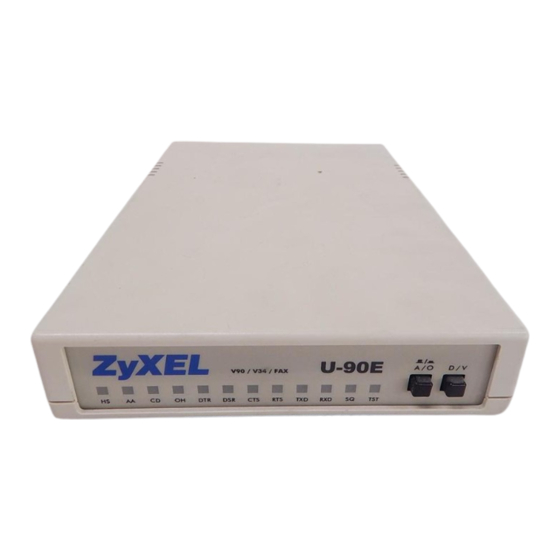
Front Panel The LEDS on the front panel indicate the operational status of the modem. Figure 2.1 shows the front panel of the U-90E. There are 12 LED indicators and two key switches. ZyXEL V90 / V34 / FAX... -
Page 28: Front Panel Leds
U-90E Data/Fax Modem 2.1.1 Front Panel LEDs The following table describes the LED indicators. Table 2-1 LED Indicators LEDs Description High Speed mode indicator, lights ON when your modem is operating in V.34 or V.90 mode; flashes when your modem is in Handshaking State. -
Page 29: Front Panel Switches
U-90E Data/Fax Modem 2.1.2 Front Panel Switches The following table describes the Front Panel Switches: Table 2-2 Front Panel Switches Switches Description Pressing the button will set the modem in originate mode and releasing it in answer mode. This switch only determines modem operation if the modem is made to go off-hook manually. -
Page 30: Rear Panel
U-90E Data/Fax Modem Rear Panel The U-90E rear panel is shown below: Figure 2-2 Rear Panel Table 2-3 Rear Panel Printed on Description U-90E Housing Power Power switch, turns the modem ON or OFF. Power Jack Input terminal for power adapter. -
Page 31: Additional Installation Requirements
U-90E Data/Fax Modem Additional Installation Requirements • In addition to the ZyXEL modem you just purchased, you must have the following equipment to operate your modem: • Computer terminal. • Available PC serial port with a high-speed 16550 UART. •... -
Page 32: Modem Configuration
U-90E Data/Fax Modem Modem Configuration There are no DIP (dual in-line package) switches or configuration settings that you need to worry about. Your modem is factory pre-set. User configurations are also conveniently stored in user selectable non-volatile memories and can be recalled as often as needed... -
Page 33: Setting Up Your Internet Connection
U-90E Data/Fax Modem Chapter 3 Setting up your Internet Connection For accessing Internet, you must install TCP/IP in your computer, configure the TCP/IP, and then create a PPP connection. Installing TCP/IP If TCP/IP is already installed in your computer, you may go to the next section about configuring the TCP/IP;... -
Page 34: Configuring Tcp/Ip
U-90E Data/Fax Modem You will see Figure 3-2 Select Network Protocol. Figure 3-2 Select Network Protocol Select Microsoft and TCP/IP, then click on OK. Configuring TCP/IP If your TCP/IP is already configured, you may go to the next section to setup a PPP connection;... -
Page 35: Figure 3-3 Network
U-90E Data/Fax Modem Figure 3-3 Network Select TCP/IP, then click Properties. You will see the following screen. Figure 3-4 IP Address In most cases, you have to select Obtain an IP address. If you have an assigned IP address from your ISP, select Specify an IP address then enter your IP address and subnet mask. -
Page 36: Creating A Dial-Up Connection
U-90E Data/Fax Modem Figure 3-5 DNS Configuration Creating a Dial-up Connection At this point, you are only one step away from accessing the Internet. Follow the instructions below to create a new dial-up connection. Click on My Computer on your desktop, select Dial-up Networking, then click on Make New Connection. -
Page 37: Figure 3-6 Make New Connection
U-90E Data/Fax Modem Figure 3-6 Make New Connection Give a name to this Dial-up Connection. For example, U-90E. Then select your new modem as the device to connect to Internet, and then click Next. You will see the following screen. -
Page 38: Figure 3-8 Completing Dial-Up Connection
U-90E Data/Fax Modem Enter your ISP's phone number, and then click Next. Figure 3-8 Completing Dial-Up Connection Click Finish. Now, you have completed dial-up setup. From now on, you can access the Internet by your new device. Modem Installation... -
Page 39: Chapter 4
Understanding AT Commands The U-90E communicates asynchronously with computers using commands. commands are used to configure and control your modem. Commands are usually sent to the modem by way of communication software, but can also be entered manually by the user with the computer keyboard. -
Page 40: Table 4-1 Modem Settings
U-90E Data/Fax Modem Once your modem is connected to your computer’s serial port and telephone line, open the Windows 95 “Accessories” program group, and open the Hyper Terminal Program. The program will prompt you for a name and Icon to use for your new connection. Type the name Test Connection and press <Enter>. -
Page 41: Dialing And Answering Techniques
U-90E Data/Fax Modem This confirms that the modem and your computer are communicating correctly. To test the telephone line connection issue the manual answer command. Type: ATA<Enter> Your modem will pick up the phone line, and try to communicate. Normally, this command is only used to answer an incoming call made from another modem, thus the high pitched tone you will hear from the speaker. -
Page 42: Auto-Answer And Hook Controls
U-90E Data/Fax Modem ATX0D, 555 1212 Dialing Without Waiting for Dial Tone: ATDT 555 1212,,,,,,R Originating a call using an Answer Tone: ATDL Redialing the Last Number Called: ATDT 800 555 1212 @ Waiting for Five Seconds of Silence: 123456,1 714 555 1212... -
Page 43: Table 4-3 Basic Commands
U-90E Data/Fax Modem If you see duplicated characters for each character you type, your modem and software both have their “echo” feature turned on. The modem command echo state is switched off ATE0 ATE1 using and on using (default). To eliminate the double characters, turn off the ATE0 software’s command echo rather than using the... -
Page 44: Modem Result Codes
The U-90E also provides result codes that show: Whether or not a Dial Tone was detected when the modem originated a call. Whether a busy signal was detected when the modem originated a call. -
Page 45: Viewing S Register Values
U-90E Data/Fax Modem If a remote telephone ring was detected when dialing. The speed, protocol, and error control/data compression method used. If an incoming ring was detected. ATXn Result codes can originate from any of eight result code sets. The command lets you choose which set of result codes your modem can use. -
Page 46: Non-Volatile Memory
Non-Volatile Memory The U-90E has an amount of memory set aside for storing user information such as frequently used phone numbers and default command settings. The latter is particularly useful when using your modem to call a variety of different locations that require different settings. -
Page 47: Saving Settings And User Profiles
U-90E Data/Fax Modem AT&Zs=n command is actually typed, unlike the ‘s’ in the command which represents a number. 4.4.3 Saving Settings and User Profiles There are some cases where you may wish to save the settings you have made as the AT&WZ... -
Page 48: Default Modem Settings For Pc's
AUTOEXEC batch file. 4.5.1 Default Modem Settings for PC’s The U-90E factory settings are configured for operation with PC type computers and communication software. In most cases, no additional settings will be required. The following are some of the default settings that are used for operation with PC computers... -
Page 49: Helpful Hints For Mac Computers
One of the most powerful shareware programs available is ZTerm. Fewer programs are available to make use of the ZyXEL's fax features. One program that has found wide acceptance is FaxSTF that can be installed like a printer driver allowing you to send faxes from almost any program which runs on your Macintosh. -
Page 50: Helpful Hints For Unix-Based Computers
In order to use your ZyXEL modem from a terminal or an X-Windows application, you need a program such as Minicom or Seyon. If you wish to make use of your ZyXEL modem's special features, special gettys such as mgetty or vgetty are needed. These programs are available from several ftp-sites. Some archives also contain source files. -
Page 51: Chapter 5
U-90E Data/Fax Modem Chapter 5 AT Command Set Summary command is a command issued by the computer/terminal to the modem through the asynchronous computer-modem interface in asynchronous data format. commands control the modem’s behavior and actions. To send an command from a computer to the modem, you must be running a communication software and the modem must be in command state. - Page 52 U-90E Data/Fax Modem Command Options Function & Description Ref. are listed as follows: 0-9, #, * Digits for dialing Pulse dialing S23.1 Tone dialing S23.1 Pause for a time specified in S8. Remaining digits will be dialed as in-band DTMF.
- Page 53 U-90E Data/Fax Modem Command Options Function & Description Ref. 'ATT' Display product information and ROM checksum Display modem link status report Display physical layer status Display Channel response for V.34 V 90 capability report V 90 power management report n=0-7 Speaker volume control.
-
Page 54: Result Code Options
U-90E Data/Fax Modem Command Options Function & Description Ref. decimal number between 0 and 255 Display value stored in S-register 'r' Download firmware to the Flash EPROM by using Xmodem protocol Sets display type for Result Codes S23.6 Display result code in numeric form. (See also S35.7 and the result code table of... - Page 55 U-90E Data/Fax Modem CONNECT • • • • • • • • RING • • • • • • • • NO CARRIER • • • • • • • • ERROR • • • • • • • •...
- Page 56 U-90E Data/Fax Modem CONNECT 51200 • • • • • CONNECT 62400 • • • • • CONNECT 41600 • • • • • CONNECT 31200 • • • • • • • CONNECT 24960 • • • • •...
-
Page 57: Extended At& Command Set
U-90E Data/Fax Modem CONNECT 32000 • • • • • • • CONNECT 30666 • • • • • • • CONNECT 29333 • • • • • • • CONNECT 28000 • • • • • • • Note: If error control result codes are enabled (X4,X5,X6,X7),the resulting message will be formatted as: X4: CARRIER Rx Rate. - Page 58 U-90E Data/Fax Modem Command Options Function & Description Ref. &C1 * CD tracks presence of carrier (See also S38.3, S42.7) &Dn Data Terminal Ready (DTR) options. (See S21.6-7 also S25) &D0 Ignore DTR signal, assume DTR is always &D1 108.1, DTR OFF-ON transition causes dial of the default number.
- Page 59 U-90E Data/Fax Modem Command Options Function & Description Ref. &L1 2W leased line &Mn Synchronous/asynchronous mode selection S14.6-7 &M0 * Asynchronous mode with data buffering &M1 Asynchronous command, synchronous data &M2 Direct asynchronous mode, no data buffering &M3 Synchronous mode &Nn...
- Page 60 U-90E Data/Fax Modem Command Options Function & Description Ref. &N62 V.34 28800 &N63 V.34 26400 &N64 V.34 24000 &N65 V.34 21600 &N66 V.34 19200 &N67 V.34 16800 &N68 V.34 14400 &N69 V.34 12000 &N70 V.34 9600 &N71 V.34 7200 &N72 V.34 4800...
- Page 61 U-90E Data/Fax Modem Command Options Function & Description Ref. &N93 V.90 36000 &N94 V.90 34666 &N95 V.90 33333 &N96 V.90 32000 &N97 V.90 30666 &N98 V.90 29333 &N99 V.90 28000 &Pn Pulse dial make/break ratio S23.2 &P0 * make / break, 39% / 61% &P1...
- Page 62 U-90E Data/Fax Modem Command Options Function & Description Ref. &T7 Initiate Remote Digital Loop-back with self test (RDL+ST) &T8 Initiate Analog Loop-back with self test. (ALB+ST) &Vn View profile settings. &V0 View current active settings. &Vn View the (n-1) user profile settings (n=1-4) &V5...
-
Page 63: Extended At* Command Set
U-90E Data/Fax Modem Command Options Function & Description Ref. to set the default dial pointer. &$ Extended 'AT&' command summary help Extended AT* Command Set Table 5-4 Extended AT* Command Set Command Options Function & Description Ref. Character length, including start, stop S15.3-4... - Page 64 Note: The command *Gn requires supervisor password checking. In security type 1, the remote site must be a ZyXEL modem. In security type 2, the remote site can be any other type of modem. The modem can store 50 (0-49) telephone numbers. If call back security is disabled, the modem will search the password table to check the remote modem’s password.
- Page 65 U-90E Data/Fax Modem Command Options Function & Description Ref. *M0 * Leased line auto-handshake on originate mode. Leased line auto-handshake on answer mode. n=0-31 Set leased line transmission power level; S17.1-4 ranges from 0 dBm to –31dBm (default: - *P11 * 11 dBm depends on the country code) (see also S35.3)
-
Page 66: At Fax Command Set
U-90E Data/Fax Modem Extended AT# Command Set Table 5-5 Extended AT# Command Set Command Options Function & Description Ref. Modem status in escape state Disable the report of modem status in escape state Enable the report of modem status in... -
Page 67: Chapter 6
U-90E Data/Fax Modem Chapter 6 Status Registers This chapter provides an overview of S-Registers (status registers) available in your U- 90E data/fax modem. S-Register Descriptions The descriptions for each S-register are given below. In most bit-mapped S-registers, the default bit value is 0. An asterisk marks non-0 default values. In some cases, default values are shown in the reference column preceded by +. -
Page 68: Extended S-Registers "Atsn=X
Bit-mapped register +000 Capture modem manufacturer information during V.42 handshake, can be displayed at ATI2 <Last Speed/Protocol> line if available (‘Flash’ or ‘ ZyXEL’ stands for ZyXEL connection) S14= Bit-mapped register: +002 Originate mode auto handshake in leased line mode. - Page 69 U-90E Data/Fax Modem Command Function and description Ref. Grant Remote Digital Loop-back test &T4 request Deny Remote Digital Loop-back &T5 test.(Default) Dial-up line (Default) &L0 2-wire leased line &L1 Internal clock (Default) &X0 External clock (from DTE) &X1 Remote clock (slave mode) &X2...
- Page 70 U-90E Data/Fax Modem Command Function and description Ref. power on Profile 2 as active settings after power on Profile 3 as active settings after power on 80 * Factory default as active settings after power on S16= Test status register...
- Page 71 U-90E Data/Fax Modem Command Function and description Ref. S18= Force modem to fix baud rate when +000 answering Disable fixed baud function 1-46 1-2E Enable baud rate to be fixed when answering. Baud rate value settings (n) the same as S20...
- Page 72 U-90E Data/Fax Modem Command Function and description Ref. 153600 bps 102400 bps 61440 bps 51200 bps 624000 bps 124800 bps 62400 bps 41600 bps 31200 bps 24960 bps 20800 bps 921600 bps Note: Only the speeds up to S20=15 are supported by auto speed detection.
- Page 73 U-90E Data/Fax Modem Command Function and description Ref. CD tracks presence of data carrier &C1 (see also S38.3) (default) CTS Follows RTS in synchronous &R0 mode. Response delay set in S26 Ignore RTS (CTS always ON) in &D2 synchronous mode. (Default) Assume DTR always On &D0...
- Page 74 U-90E Data/Fax Modem Command Function and description Ref. ATX4 ATX5, error control result code is enabled (Default) ATX6, error control result code is enabled ATX7, error control result code is enabled Display result code in numeric format (see S35.7) Display result code in verbose format V1...
- Page 75 U-90E Data/Fax Modem Command Function and description Ref. V.42 + V.42bis (compatible with &K2) &K4 (default) Flow control disabled &H0 Hardware (RTS/CTS) flow control &H3 (default) Software (XON/XOFF) flow control &H4 Reserved &H5 Signal quality No response to poor signal quality...
- Page 76 U-90E Data/Fax Modem Command Function and description Ref. also S18, S44b6) DTE/DCE rate is fixed at the DTE &B1 setting, range from 300-460.8 Kbps (default, also see S18, S44b6) Select V.22 for 1200 bps communication Select Bell 212A for 1200 bps...
- Page 77 *Rab profile a Security function control Disable security function (Default) Enable type 1 security with password check. (ZyXEL to ZyXEL only) Enable type 1 security with password check and call-back (ZyXEL to ZyXEL only) Enable type 2 security with password...
- Page 78 U-90E Data/Fax Modem Command Function and description Ref. DCD ON/OFF sequence follows &C1 UNIX standard, DCD ON before S21.4 connect message is sent, DCD off after last DCE response is sent Auto-mode fax receiving &N0 disabled.,hang up if a fax call is received Disable MNP5 negotiation.
- Page 79 U-90E Data/Fax Modem Command Function and description Ref. first ring. Ignore calling tone, not to be used as fax detection S42= Bit mapped register +000 Enables throughput averaging CND message will be forced on even if ATQ2 is set Disable escape sequence code in answer mode Disable V.17 14,400 Fax in calling...
- Page 80 U-90E Data/Fax Modem Command Function and description Ref. S46= CND silence detection interval +028 0-255 0-FF To process the CND, silence must be detected for the specified interval, in 20 ms units S48= Bit-mapped register +000 Cause CND information to be...
- Page 81 U-90E Data/Fax Modem Command Function and description Ref. Disables fax-CNG tone detection (Default) Reports RING for fax CNG tone Reports RING 1 for fax CNG tone Reports RING 2 for fax CNG tone Disables data CNG tone detection Reports RING for data CNG tone...
-
Page 83: Chapter 7
Connecting to a Leased Line The leased line jack of U-90E is the same as dial-up line. You can connect leased line to the dial-up line jack. The leased line phone jack pin assignments are shown in the Appendix. -
Page 84: Leased Line Handshaking
U-90E Data/Fax Modem AT-Command Description AT*P0 The default is –11dBm. The adjustable range is from 0 to – . . . AT*P31 31dBm, effective in leased-line operation only. Leased Line Handshaking In a typical dial-up connection, the originating modem dials the number and waits for the answering modem's carrier signal. -
Page 85: Terminating A Leased Line Connection
U-90E Data/Fax Modem Table 7-3 AT Command for Auto Handshake AT-Command Description AT*M0 When operating over a leased line, modem will start handshaking in originate mode. (Default) AT*M1 When operating over a leased line, modem will start handshaking in answer mode. -
Page 87: Chapter 8
Chapter 8 Synchronous Mode Operation This chapter introduces you to the use of U-90E modem for synchronous operation. Use the modem as a synchronous modem when it is connected to a synchronous computer or terminal. Make sure that the remote modem and system are also set to synchronous. -
Page 88: Clock Options
In this case, you must set s58.5 to 1 to let the received clock lock with external clock. Half-Duplex operation For a half-duplex modem, the carrier only exists in one direction at any specific time. The are two kind of half-duplex mode provided by U-90E. Synchronous Mode Operation... -
Page 89: Pseudo Cd
U-90E Data/Fax Modem 8.3.1 Pseudo CD Set s12.7 to 1 can enable this function. When s12.7 is set, CD (Carrier Detect) signal will light up only when there is received data present. This function is often used together with RTS option set to &R0. (CTS track RTS). Please take note that it would drop the line when CD signal is on for more than 20 second unless s12.6 is set to 1. -
Page 91: Chapter 9
MNP4 and MNP3. V.42 supports both LAPM (Link Access Procedure for Modems) and MNP4. A V.42 handshaking will try an LAPM connection first, and if not successful, it will try MNP4. The maximum data block size used in the U-90E modem is 256 bytes. -
Page 92: Data Compression
The U-90E modems support both V.42bis and MNP5 data compression protocols. Data compression needs an error-free data link to work correctly, otherwise the corrupted compressed data stream will ruin the decompression process. Hence MNP5 is used with MNP4 error control and V.42bis is used with V.42 error control. -
Page 93: Flow Control
U-90E Data/Fax Modem Flow Control This feature refers to stopping and restarting the flow of data into and out of the modem’s transmission and receiving data buffers. Flow control is necessary so that a device does not receive more data than it can handle. The U90E provide two kinds of flow control methods. -
Page 95: Chapter 10
U-90E Data/Fax Modem Chapter 10 Special Functions This chapter describes special features of the U-90E, and offers instructions on how to use them. 10.1 Security Functions Your modem provides a security function that prevents unauthorized users from making connections. Two types of security functions are provided. -
Page 96: User Passwords
The attempt will be rejected if the entered password is not correct. The default supervisor password is ZyXEL when the modem is shipped from the factory. This supervisor password is also the password sent for automatic password checking in a type AT*HS 1 connection. -
Page 97: Remote Configuration
10.2 Remote Configuration Remote configuration on the U-90E is provided as a profile by profile batch mode. Batch mode remote configuration is a convenient feature allowing you to pre-configure a remote modem in one of the local modem’s user profiles and send it to the remote modem in one action. -
Page 98: Table 10-2 At*Rab Command
U-90E Data/Fax Modem Local profile modification is done by loading the remote profile as the active settings and then modifying and saving the active settings back to the profile. Then the connection is reestablished and the profile transmitted to the remote modem. -
Page 99: Caller Number Delivery (Caller Id)
U-90E Data/Fax Modem 10.3 Caller Number Delivery (Caller ID) Caller Number Delivery (CND), commonly called Caller ID, is a new kind of phone service that may be offered by your local phone company. Check your phone company for availability. You must subscribe to it and usually pay an additional monthly service charge this service. - Page 100 U-90E Data/Fax Modem RING MM is the two-digit month message, DD is the two-digit date message, hh is the hour and mm is the minute of the time, and CALLER_ID is the phone number of the caller or CALLER_NM his/her name.
-
Page 101: Distinctive Ring
U-90E Data/Fax Modem RING TIME: 04-28 12:30 REASON FOR NO NUMBER: OUT_OF_AREA REASON FOR NO NAME: PRIVACY RING AT*T The last CND message that the modem received can be displayed by using the command. Setting S48.0=1 will cause the modem to report CND information in its ASCII coded hexadecimal raw data format. -
Page 102: Table 10-4 Ring Control
U-90E Data/Fax Modem someone picks up the phone. You can also have the answering machine answer only the voice ring. A more complicated use is that you can have one number for multiple uses, such as one number for both data and fax. -
Page 103: Extended Distinctive Ring (Edr)
U-90E Data/Fax Modem Note: Countries other than the U.S. may have different specifications for different ring types. The manufacturer may append other sets of ring type specifications to suit each country's needs. 10.5 Extended Distinctive Ring (EDR) Extended Distinctive Ring (EDR) is a special feature designed for single telephone line home use to receive fax or data calls without interfering with regular voice calls. -
Page 104: Setting Up Edr
U-90E Data/Fax Modem If the remote caller is an unattended fax machine, it will send a CNG tone for a period of time. The modem will detect the CNG tone and report RING to the software immediately. The software application can then issue commands to answer the call and receive the fax. -
Page 105: Edr Application Example
U-90E Data/Fax Modem Bits Bin. Dec. Description (1,0) Disable EDR (default). Report RING twice. Report RING four times. Report RING six times. EDR detection (either CNG or DTMF tones) will be disabled once detection occurs. However, a customer’s program might not answer because the setting of the software may require multiple rings. -
Page 106: On-Line Help
AT& enable you to view commands respectively. 10.7 V.25bis Command Set U-90E supports V.25bis command set. V.25bis is a dialing command set standard defined AT*I1 by the ITU-T. It supports both asynchronous and synchronous dialing. Use enable V.25 commands. Special Functions... -
Page 107: Table 10-6 V.25 Command Set
U-90E Data/Fax Modem The following table lists V.25bis commands and their formats. Table 10-6 V.25 Command Set Syntax Command with parameters Descriptions CRN <dial string> Call request with number provided CRS n Call request with number from memory location “n”. -
Page 109: Chapter 11
Chapter 11 Fax Operation The U-90E can be used as a fax machine. In the sections below, we will describe how the modem works as a fax machine, the ITU-T T.30 fax protocol, and the Class 1 and 2.0 fax commands. -
Page 110: Modem As Fax Machine
The RS-232 serial connection or the ZyXEL serial port interface connects your modem to the computer. Your modem uses the same interface for both data and fax applications. In fax operations, the modem performs protocol handshaking and image data transfer. -
Page 111: Fax Command Sets
U-90E Data/Fax Modem 11.3 Fax Command sets The U-90E supports two command sets for fax operation: Class 1 command set TIA 592 Class 2.0 command set 11.3.1 Defining the Fax Command Sets The EIA Class 1 fax commands are a set of AT fax commands defined by EIA/TIA (Telecommunications Industry Association) for controlling fax/modems from a computer through the serial RS-232 interface. -
Page 112: Table 11-2 Mod Parameters
U-90E Data/Fax Modem pauses +FRS=n Wait for Silence n=0-255 in 10 ms units. +FTM=<MOD> Transmit Data with <MOD> See table 10.2 Carrier +FRM=<MOD> Receive Data with <MOD> See table 10.2 Carrier +FTH=n Transmit HDLC Data with <MOD>=3 Carrier +FRH=n Receive HDLC Data with <MOD>=3 Carrier... -
Page 113: Service Class 2.0 Commands
U-90E Data/Fax Modem 11.3.3 Service Class 2.0 Commands Table 11-3 Service Class 2.0 Commands Command Description Value +FDT Transmit phase C data command: releases the DCE to proceed with the negotiation +FDR Receive phase C data command: initiates document reception... - Page 114 U-90E Data/Fax Modem Command Description Value Page Length ln=0:A4;297mm ln=1:B4;364mm ln=2:unlimited length Data Compression Format df=0:1-D df=1:2-D Error Correction ec=0:Disable Binary File Transfer bf=0:Disable Minimum Scan Time/Line st=0:0 ms st=1:5 ms st=2:10 ms (normal); 5 ms (fine) st=3:10 ms st=4:20 ms (normal);...
- Page 115 U-90E Data/Fax Modem Command Description Value n=1:Enable +FNR=rpr,tpr,idr,nsr Negotiation Reporting Enable rpr= 0:Receiver parameters are not reported rpr=1:Receiver parameters are reported tpr= 0:Transmitter parameters are not reported tpr=1:Transmitter parameters are reported idr= 0: ID Strings are not reported idr=1: ID Strings are reported...
- Page 116 U-90E Data/Fax Modem Command Description Value detection by the DCE n>0:Serial rate is fixed at the value multiplied by 2400 bps +FBO=n Phase C Data Bit Order n=0:Selects direct bit order n=1:Selects reversed bit order +FEA=n Phase C Received EOL...
-
Page 117: Status Report Result Codes
512,256 11.4 Status Report Result Codes When the U-90E is in fax mode, each ATD or ATA command will make the modem try to establish a fax connection. Your modem will send a status report result code back to the DTE (computer). -
Page 119: Chapter 12
Voice capability stands for the modem’s ability to digitizalize incoming voice messages, which the computer stores and forwards. Only a limited voice function that supports DTMF (Dual Tone Multi Frequency) detection and generation is provided by U-90E modem. 12.1 The voice AT command specification... -
Page 120: Voice Shield Dte Command
U-90E Data/Fax Modem Command Function Option Default Description provided with power. +VTS Tone Generation [x,y,z],{x,z},x [x,y,z],{x,z} ----------------- ---------------------------------------------------- [x,y,z]: [x,y,z]: x: 0-3000 Hz x: first frequency y: 0-3000 Hz y: second frequency z: 0- 1000 z: duration in 0.1 sec. - Page 121 U-90E Data/Fax Modem <DLE>c Calling Tone <DLE>d Dial tone <DLE>e European Data Modem Calling Tone <DLE>f Bell Answer Tone <DLE><ETX> End of stream Special Functions 12-3...
-
Page 123: Chapter 13
U-90E Data/Fax Modem Chapter 13 Diagnostics The U-90E modems provide several diagnostic capabilities: • Power-on Self-Test • Analog Loopback Test • Analog Loopback with Self-Test • Local Digital Loopback Test • Remote Digital Loopback Test • Remote Digital Loopback with Self-Test •... -
Page 124: Loopback Tests
The screen should show the data you have sent to the modem. The U-90E will have the TST LED On during the test. This test can only be initiated while the modem is off-line 13.2.2 Analog Loopback with Self-test (AT&T8) -
Page 125: Remote Digital Loopback Test (At&T6)
U-90E Data/Fax Modem The U-90E will have the TST LED On during the test. This test can be initiated by the local modem when the modems are on-line. 13.2.4 Remote Digital Loopback Test (AT&T6) This test will request the remote modem to do a digital loopback. During testing, the local modem will send a remote digital loopback request to the remote modem according to V.54. -
Page 126: Link Status Report (Ati2)
U-90E Data/Fax Modem 13.4 Link Status Report (ATI2) During a connection, the modem will record information about link operations. You can ATI2 use the command to view the link status report. The V.90/V.34 Link Status Report output appears as follows:... -
Page 127: Table 13-2 Output Value Description
U-90E Data/Fax Modem Table 13-2 Output Value Description Output Output Value Description Parameter Chars Sent Number of characters DTE has sent to modem Chars Number of characters modem has sent to DTE Received Octets Sent Number of data bytes sent to remote modem... - Page 128 U-90E Data/Fax Modem Output Output Value Description Parameter Resent expiration Carrier lost On-line Protocol error S7 Timer timeout DTR dropped Carrier lost 1 Carrier lost 2 Speed no match Security check EC negotiation failure Keyboard abort ATH command Inactivity FRMR received...
-
Page 129: Indicator Lights
U-90E Data/Fax Modem Indicator Lights 13.4.1 Retransmission Indicator In the error control mode, an error occurring in the link will cause the data to be re- transmitted. At the same time, the AA LED will flash. This also indicates the quality of the line 13.4.2 Dialing Indicator... -
Page 131: Chapter 14
Chapter 14 Upgrading Your Modem 14.1 Upgrading by Flash EPROM 1. Obtain the new firmware by downloading from the ZyXEL BBS, WWW or FTP site. See Contacting ZyXEL for the FTP address. 2. Turn on your computer. 3. Turn on your modem. -
Page 132: Kernel Recovery Mode
U-90E Data/Fax Modem 14.2 Kernel Recovery Mode Your modem is equipped with ZyXEL’s exclusive Kernel Recovery Mode. This unique feature enables quick recovery from failed flash uploads. With other modems, a failed flash upload usually results in the user having to return the modem to the factory for repair. -
Page 133: Chapter 15
U-90E Data/Fax Modem Chapter 15 Troubleshooting Your modem is designed to provide years of ultra high speed satisfaction. In the unlikely event of you encountering problems using your modem, the tips in this section will help you to identify and resolve them. Most modem problems are a result of incorrect cabling or settings within your communications or fax software. - Page 134 U-90E Data/Fax Modem 2. You may have omitted the characters AT from the beginning of the command line. These characters must appear at the beginning of each command line. 3. You may have typed the commands when your modem was in data state instead of the command state.
-
Page 135: Command Echo Problems
U-90E Data/Fax Modem 15.2 Command Echo Problems Problem You do not see any typed characters on your computer screen. Solutions 1. Make sure the DTR LED is ON. If it is OFF, make sure your communications software is using the same COM port as your modem. -
Page 136: Dialing Problems
RING result codes. 3. Check that the DTR LED is ON, and that the AA LED flickers with each incoming ring. If the LEDs do not respond in this way, refer to your ZyXEL User’s Guide. -
Page 137: Data Transfer Problems
U-90E Data/Fax Modem 2. You are using touchtone dialing on a line that requires pulse dialing. Change your communications software to use pulse dialing. 3. Unplug the telephone line cable from the computer and connect it directly to a telephone handset. Check for dial tone. If there is none, the problem is in the telephone line. - Page 138 1. The remote system may have hung up. Type ATI2 and press Enter to view the link status report, which will include the reason for the disconnect. For information on understanding this report, refer to your ZyXEL User’s Guide. 2. You may have subscribed to Call Waiting and received an incoming call that interrupted your data connection.
-
Page 139: Glossary
U-90E Data/Fax Modem Appendix A Glossary Analog: Not digital. Analog quantities may have any value. Analog loopback test: Testing method in which the modem's analog output signal is connected to the analog input. Answer: In a connection between two modems, one modem works as the recipient (in answer mode) and the second modem as the initiator (originate mode). - Page 140 CD: See DCD. Class 2: A standard for fax transfers using a fax modem. Currently several drafts exist which are incompatible with each other. ZyXEL modems support the draft PN-2388 of Aug. 20th 1990, and the final 2.0 standard. CNG: Call negotiation tone. A calling fax machine sends this tone before connecting to quickly establish a fax connection.
- Page 141 DIP switch: Dual inline package switch. DIP switches are abundant in the world of electronic equipment. They are used to set certain parameters on a printer, modem or other peripheral devices. You will not find any DIP switches in ZyXEL modems. ZyXEL modems let you perform all settings from the front panel or through command sequences.
- Page 142 FIFO-Buffer: First-in-first-out buffer. A buffer of this type is used in the 16550 type UARTs which allow higher data throughput rates on PCs. Firmware: The ZyXEL modems' system software is located in flash EPROMs. Depending on the size of the EPROM(s), some features may or may not be available.
- Page 143 U-90E Data/Fax Modem Hook-Flash: The hook-flash is a signal used in a dial sequence. This signal may be used for call transfers or to request an outside line on certain PABX. Hz: Hertz. A unit of measurement for frequency. Cycles per second.
- Page 144 QUIET: A state in the voice mode of ZyXEL modems. Quiet is detected after a long pause in voice data. RAM: Random Access Memory - working memory. The modem uses it among many other uses to store information on sent, but not yet acknowledged data.
- Page 145 RTS/CTS: See CTS/RTS. RXD: Line for the received data on a serial port following RS-232C. Security function: Features of the ZyXEL modems which help deny illegitimate contacts to your computer system through telephone lines. Self-test: Ability of the modem to check its components and operations for faults.
- Page 146 U-90E Data/Fax Modem Stop bit: In asynchronous transfers, every character is terminated by one or two stop bits which show where a character ends. Synchronous : In synchronous transfer, a dedicated control signal line transmits a clock signal which paces the transmitted data. In highspeed connections, the transfer between two modems is always synchronous, even if the DCE to DTE connection is asynchronous.
- Page 147 U-90E Data/Fax Modem ZModem: A file transfer protocol with variable block size, reinitiation of aborted transfers and transfer of several files in one transfer along with file (and path) names. Glossary...
- Page 148 U-90E Data/Fax Modem Appendix B EIA-232D Interface Signal ITU-TSS Pin/Signal Description Direction Signal Name Signal DTE-DCE Name Protective Ground (GND). → Transmitted Data (TXD). ← Received Data (RXD). → Request To Send (RTS). ← Clear To Send (CTS). ← Data Set Ready (DSR).
- Page 149 Appendix C Phone Jack Pin Assignments The ZyXEL U 90E modem features two RJ-11 phone jacks, one for 2-wire dial-up and 2- wire leased line connection (LINE) and one for an optional connection to a telephone set (PHONE). The signals on these pins are:...
- Page 151 U-90E Data/Fax Modem Index AT commands, 4-1, 4-2, 4-3, 4-5, 4-6, 4-7, 5-1, 10- Fax Command sets, 11-2 2, 14-2, 15-1 Fax Operation # commands, 5-15 Basics, 11-1 & commands, 5-7 ITU-T T.30 fax protocol, 11-2 * commands, 5-13 Using Modem as Fax, 11-1...
- Page 152 U-90E Data/Fax Modem Software tips, 4-10 Levels, 10-1 Microsoft Windows, 4-1 User Passwords, 10-2 Modem Installation, 2-4 SMARTDRV, 4-9 Modem operation, 4-1 S-register, 4-6, 4-7, 5-3, 6-1, 6-15, 10-7, 10-9 Non-Volatile Memory, 4-7 Synchronous Mode Operation, 1-5, 8-1 On-line Help, 10-10...
Need help?
Do you have a question about the U-90E and is the answer not in the manual?
Questions and answers