Advertisement
Quick Links
www.ti.com
EVM User's Guide: TPS7N53EVM-138
TPS7N53EVM-138 Evaluation Module
Description
The TPS7N53EVM-138 is designed to help design
engineers evaluate the operation and performance of
the TPS7N53 linear regulator for possible use in a
circuit application. This particular EVM configuration
contains a single low-noise, high accuracy, linear
regulator for a wide range of applications. The
regulator is capable of delivering up to 3A to the
load with low VIN to VOUT dropout voltage. A high
performance load transient circuit is included to assist
the user with high-speed load transient testing. Low
inductive current loops are integrated into the board
to assist the user with input and output current
measurements.
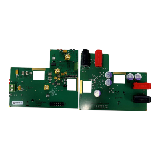
TPS7N53EVM-138 (Top View)
SBVU085 – DECEMBER 2024
Submit Document Feedback
Features
•
Input voltage range: 1.1V to 2.2V
•
Output voltage noise: 2.2μV
•
Low dropout: 95mV(typ) at 3A
•
Adjustable output voltage range: 0.5V to 1.5V
•
Adjustable soft-start inrush control
•
Open-drain, power-good (PG) output
•
Package: 3mm x 3mm, 16-pin WQFN
Applications
•
Macro Remote Radio Units (RRU)
•
Outdoor Backhaul Units
•
Active Antenna System mMIMO (AAS)
•
Ultrasound Scanners
•
Lab and Field Instrumentation
•
Sensor, Imaging, and Radar
Copyright © 2024 Texas Instruments Incorporated
RMS
TPS7N53EVM-138 (Bottom View)
TPS7N53EVM-138 Evaluation Module
Description
1
Advertisement

Subscribe to Our Youtube Channel
Related Manuals for Texas Instruments TPS7N53EVM-138


Summary of Contents for Texas Instruments TPS7N53EVM-138
- Page 1 Description EVM User's Guide: TPS7N53EVM-138 TPS7N53EVM-138 Evaluation Module Description Features The TPS7N53EVM-138 is designed to help design • Input voltage range: 1.1V to 2.2V engineers evaluate the operation and performance of • Output voltage noise: 2.2μV the TPS7N53 linear regulator for possible use in a •...
- Page 2 1 Evaluation Module Overview 1.1 Introduction The TPS7N53EVM-138 evaluation module (EVM) is a linear regulator circuit that achieves low-noise (2.2μV ), ultra-low-dropout (95mV typ), and high PSRR in a small footprint. The EVM has the capability to operate over an input voltage range of 1.1V to 2.2V, providing a regulated output of 0.5V to 1.5V, with the capability to source 3A.
- Page 3 Open-drain, power-good indicator pin for the low-dropout regulator (LDO) output voltage. Soft-start connection. Enable connection. Regulated output voltage. Reference connection. Noise-reduction connection. GND connection. SBVU085 – DECEMBER 2024 TPS7N53EVM-138 Evaluation Module Submit Document Feedback Copyright © 2024 Texas Instruments Incorporated...
- Page 4 PG and REF resistors installed. These components provide an implementation example, as illustrated by TPS7N53EVM-138 With Current Probes Attached. The TPS7N53 EVM is assembled for an output voltage of 0.75V. For other voltage options, resistor R4 can be modified as necessary.
- Page 5 Optional kelvin sense points are provided using the SMA connectors J6 (V ) and J4 (V ) and MMCX connectors J5 (V ) and J1 (V SBVU085 – DECEMBER 2024 TPS7N53EVM-138 Evaluation Module Submit Document Feedback Copyright © 2024 Texas Instruments Incorporated...
- Page 6 50Ω output, in a 0V DC to 5V DC square pulse. If necessary, burst mode can be configured in the function generator for repetitive, low duty cycle, load transient testing. TPS7N53EVM-138 Evaluation Module SBVU085 – DECEMBER 2024 Submit Document Feedback Copyright © 2024 Texas Instruments Incorporated...
- Page 7 = 1nF = 100nF = Open = 10nF -0.2 1000 1200 1400 1600 1800 2000 Time (sec) Figure 3-1. Start-Up Response SBVU085 – DECEMBER 2024 TPS7N53EVM-138 Evaluation Module Submit Document Feedback Copyright © 2024 Texas Instruments Incorporated...
- Page 8 Time (sec) Figure 3-2. Load Transient Response 10.5 2.25 VOUT 1.75 1.25 0.75 -1.5 0.25 -4.5 1000 Time (sec) Figure 3-3. Line Transient Response TPS7N53EVM-138 Evaluation Module SBVU085 – DECEMBER 2024 Submit Document Feedback Copyright © 2024 Texas Instruments Incorporated...
- Page 9 4.1 Schematics Figure 4-1 through Figure 4-3 show the EVM schematics. Figure 4-1. TPS7N53EVM Schematic Figure 4-2. Input Capacitor Schematic Figure 4-3. Load Transient Schematic SBVU085 – DECEMBER 2024 TPS7N53EVM-138 Evaluation Module Submit Document Feedback Copyright © 2024 Texas Instruments Incorporated...
- Page 10 Figure 4-4. Top Assembly Layer and Silkscreen Figure 4-5. Top Layer Routing Figure 4-6. Layer 2 Figure 4-7. Layer 3 Figure 4-8. Layer 4 Figure 4-9. Layer 5 TPS7N53EVM-138 Evaluation Module SBVU085 – DECEMBER 2024 Submit Document Feedback Copyright © 2024 Texas Instruments Incorporated...
- Page 11 Hardware Design Files Figure 4-10. Layer 6 Figure 4-11. Layer 7 Figure 4-12. Bottom Layer Routing Figure 4-13. Bottom Assembly Layer and Silkscreen SBVU085 – DECEMBER 2024 TPS7N53EVM-138 Evaluation Module Submit Document Feedback Copyright © 2024 Texas Instruments Incorporated...
- Page 12 Panasonic R16, R17 RMCF0603ZT0R00 Stackpole RES, 0, 1%, 0.1 W, AEC-Q200 Grade 0, 0603 Electronics Inc RES, 50, 2%, 11 W, 1206 RCP1206W50R0GEB Vishay-Dale TPS7N53EVM-138 Evaluation Module SBVU085 – DECEMBER 2024 Submit Document Feedback Copyright © 2024 Texas Instruments Incorporated...
- Page 13 6.1 Trademarks LeCroy ™ is a trademark of Teledyne LeCroy. TI E2E ™ is a trademark of Texas Instruments. Kapton ® is a registered trademark of DuPont. All trademarks are the property of their respective owners. 7 Related Documentation For development support see the following: •...
- Page 14 STANDARD TERMS FOR EVALUATION MODULES Delivery: TI delivers TI evaluation boards, kits, or modules, including any accompanying demonstration software, components, and/or documentation which may be provided together or separately (collectively, an “EVM” or “EVMs”) to the User (“User”) in accordance with the terms set forth herein.
- Page 15 www.ti.com Regulatory Notices: 3.1 United States 3.1.1 Notice applicable to EVMs not FCC-Approved: FCC NOTICE: This kit is designed to allow product developers to evaluate electronic components, circuitry, or software associated with the kit to determine whether to incorporate such items in a finished product and software developers to write software applications for use with the end product.
- Page 16 www.ti.com Concernant les EVMs avec antennes détachables Conformément à la réglementation d'Industrie Canada, le présent émetteur radio peut fonctionner avec une antenne d'un type et d'un gain maximal (ou inférieur) approuvé pour l'émetteur par Industrie Canada. Dans le but de réduire les risques de brouillage radioélectrique à...
- Page 17 www.ti.com EVM Use Restrictions and Warnings: 4.1 EVMS ARE NOT FOR USE IN FUNCTIONAL SAFETY AND/OR SAFETY CRITICAL EVALUATIONS, INCLUDING BUT NOT LIMITED TO EVALUATIONS OF LIFE SUPPORT APPLICATIONS. 4.2 User must read and apply the user guide and other available documentation provided by TI regarding the EVM prior to handling or using the EVM, including without limitation any warning or restriction notices.
- Page 18 Notwithstanding the foregoing, any judgment may be enforced in any United States or foreign court, and TI may seek injunctive relief in any United States or foreign court. Mailing Address: Texas Instruments, Post Office Box 655303, Dallas, Texas 75265 Copyright © 2023, Texas Instruments Incorporated...
- Page 19 TI products. TI’s provision of these resources does not expand or otherwise alter TI’s applicable warranties or warranty disclaimers for TI products. TI objects to and rejects any additional or different terms you may have proposed. IMPORTANT NOTICE Mailing Address: Texas Instruments, Post Office Box 655303, Dallas, Texas 75265 Copyright © 2024, Texas Instruments Incorporated...
Need help?
Do you have a question about the TPS7N53EVM-138 and is the answer not in the manual?
Questions and answers