Table of Contents
Advertisement
Quick Links
This user's guide describes the operational use of the TPS7A52EVM-031 evaluation module (EVM) as a
reference design for engineering demonstration and evaluation of the TPS7A52EVM-031, low-dropout
linear regulator (LDO). Included in this user's guide are setup and operating instructions, thermal and
layout guidelines, a printed-circuit board (PCB) layout, a schematic diagram, and a bill of materials (BOM).
Throughout this document, the terms demonstration kit, evaluation board, EVM, and evaluation module
are synonymous with the TPS7A52EVM-031.
The following related documents are available through the Texas Instruments web site at www.ti.com.
SBVU058 – December 2019
Submit Documentation Feedback
TPS7A52EVM-031 Evaluation Module
Table 1. Related Documentation
Device
TPS7A52-Q1
Copyright © 2019, Texas Instruments Incorporated
SBVU058 – December 2019
Literature Number
SBVS296
TPS7A52EVM-031 Evaluation Module
User's Guide
1
Advertisement
Table of Contents

Related Manuals for Texas Instruments TPS7A52EVM-031


Summary of Contents for Texas Instruments TPS7A52EVM-031
-
Page 1: Related Documentation
SBVU058 – December 2019 TPS7A52EVM-031 Evaluation Module This user’s guide describes the operational use of the TPS7A52EVM-031 evaluation module (EVM) as a reference design for engineering demonstration and evaluation of the TPS7A52EVM-031, low-dropout linear regulator (LDO). Included in this user’s guide are setup and operating instructions, thermal and layout guidelines, a printed-circuit board (PCB) layout, a schematic diagram, and a bill of materials (BOM). -
Page 2: Table Of Contents
Bottom Layer Routing ..................... TPS7A52EVM-031 Schematic List of Tables ..................... Related Documentation ....................TPS7A52EVM-031 BOM Trademarks All trademarks are the property of their respective owners. TPS7A52EVM-031 Evaluation Module SBVU058 – December 2019 Submit Documentation Feedback Copyright © 2019, Texas Instruments Incorporated... -
Page 3: Introduction
Introduction Texas Instruments' TPS7A52EVM-031 EVM helps design engineers evaluate the operation and performance of the TPS7A5201RPS device for possible use in a circuit application. This particular EVM configuration contains a single low-noise, high-PSRR linear regulator for radar applications. The regulator is capable of delivering up to 4 A to the load with ultra-low VIN to VOUT dropout voltage. -
Page 4: Evm Setup
EVM Setup www.ti.com EVM Setup This section describes how to properly connect and set up the TPS7A52EVM-031, including the jumpers and connectors on the EVM board. Input/Output Connectors and Jumper Descriptions 2.1.1 J1 – VIN Input power-supply voltage SMA jack connector. -
Page 5: Soldering Guidelines
4. Connect a 0-A to 4-A load between OUT and GND. The connector used depends on the desired output current. 5. Disable the output by floating J3. SBVU058 – December 2019 TPS7A52EVM-031 Evaluation Module Submit Documentation Feedback Copyright © 2019, Texas Instruments Incorporated... -
Page 6: Operation
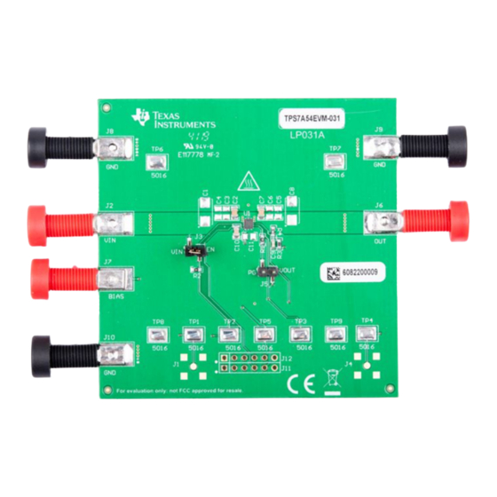
3. Vary the respective load and input voltage as necessary for test purposes. PCB Layout Figure 1 Figure 5 illustrate the PCB layout for this EVM. Figure 1. Top Composite View Figure 2. Top Layer Routing TPS7A52EVM-031 Evaluation Module SBVU058 – December 2019 Submit Documentation Feedback Copyright © 2019, Texas Instruments Incorporated... - Page 7 PCB Layout www.ti.com Figure 3. Mid Layer 1 Routing Figure 4. Mid Layer 2 Routing Figure 5. Bottom Layer Routing SBVU058 – December 2019 TPS7A52EVM-031 Evaluation Module Submit Documentation Feedback Copyright © 2019, Texas Instruments Incorporated...
-
Page 8: Schematic
68uF BIAS 3.0 V to 6.5 V BIAS BIAS 11.8k 10nF NR/SS BIAS 10nF 3.74k TPS7A5201RPST 10uF VOUT VOUT BIAS Figure 6. TPS7A52EVM-031 Schematic TPS7A52EVM-031 Evaluation Module SBVU058 – December 2019 Submit Documentation Feedback Copyright © 2019, Texas Instruments Incorporated... -
Page 9: Bill Of Materials
These assemblies must comply with workmanship standards IPC-A-610 Class 2. Unless otherwise noted in the Alternate Part Number or Alternate Manufacturer columns, all parts may be substituted with equivalents. SBVU058 – December 2019 TPS7A52EVM-031 Evaluation Module Submit Documentation Feedback Copyright © 2019, Texas Instruments Incorporated... - Page 10 STANDARD TERMS FOR EVALUATION MODULES Delivery: TI delivers TI evaluation boards, kits, or modules, including any accompanying demonstration software, components, and/or documentation which may be provided together or separately (collectively, an “EVM” or “EVMs”) to the User (“User”) in accordance with the terms set forth herein.
- Page 11 www.ti.com Regulatory Notices: 3.1 United States 3.1.1 Notice applicable to EVMs not FCC-Approved: FCC NOTICE: This kit is designed to allow product developers to evaluate electronic components, circuitry, or software associated with the kit to determine whether to incorporate such items in a finished product and software developers to write software applications for use with the end product.
- Page 12 www.ti.com Concernant les EVMs avec antennes détachables Conformément à la réglementation d'Industrie Canada, le présent émetteur radio peut fonctionner avec une antenne d'un type et d'un gain maximal (ou inférieur) approuvé pour l'émetteur par Industrie Canada. Dans le but de réduire les risques de brouillage radioélectrique à...
- Page 13 www.ti.com EVM Use Restrictions and Warnings: 4.1 EVMS ARE NOT FOR USE IN FUNCTIONAL SAFETY AND/OR SAFETY CRITICAL EVALUATIONS, INCLUDING BUT NOT LIMITED TO EVALUATIONS OF LIFE SUPPORT APPLICATIONS. 4.2 User must read and apply the user guide and other available documentation provided by TI regarding the EVM prior to handling or using the EVM, including without limitation any warning or restriction notices.
- Page 14 Notwithstanding the foregoing, any judgment may be enforced in any United States or foreign court, and TI may seek injunctive relief in any United States or foreign court. Mailing Address: Texas Instruments, Post Office Box 655303, Dallas, Texas 75265 Copyright © 2019, Texas Instruments Incorporated...
- Page 15 TI products. TI’s provision of these resources does not expand or otherwise alter TI’s applicable warranties or warranty disclaimers for TI products. Mailing Address: Texas Instruments, Post Office Box 655303, Dallas, Texas 75265 Copyright © 2019, Texas Instruments Incorporated...
Need help?
Do you have a question about the TPS7A52EVM-031 and is the answer not in the manual?
Questions and answers