Table of Contents
Advertisement
Quick Links
INSTALLATION AND
OPERATING MANUAL
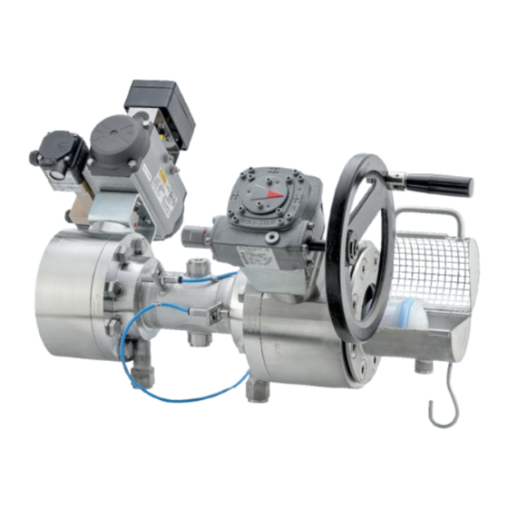
EB 28k
Translation of the original manual
BR 28k head station • DIN and ANSI version
to combine with actuators and manual gears,
for use in pig-enabled pipes
July 2024 edition
PFEIFFER Chemie-Armaturenbau GmbH · Hooghe Weg 41 · 47906 Kempen
Phone: 02152 2005-0 · Fax: 02152 1580
sales-pfeiffer-de@samsongroup.com · www.pfeiffer-armaturen.com
Advertisement
Table of Contents

Related Manuals for Samson EB 28k


Summary of Contents for Samson EB 28k
- Page 1 INSTALLATION AND OPERATING MANUAL EB 28k Translation of the original manual BR 28k head station • DIN and ANSI version to combine with actuators and manual gears, for use in pig-enabled pipes July 2024 edition PFEIFFER Chemie-Armaturenbau GmbH · Hooghe Weg 41 · 47906 Kempen Phone: 02152 2005-0 ·...
- Page 2 Note regarding this installation and operating manual This Installation and Operating Manual (EB) provides guidance for safe assembly and operation. The notes and instructions in this EB are binding when handling PFEIFFER devices. The fi gures and illustrations in this EB are examples and must therefore be considered as such.
-
Page 3: Table Of Contents
Content Content Safety instructions and safety measures Notes regarding possible severe personnel injury Notes regarding possible personnel injury Notes regarding possible property damage Warning notes on the device Markings on the device Marking Guidelines BR 28k Material marking Design and principle of operation Variants Additional fi... - Page 4 Content Start-up Operation General Operating the head station Example operation 7.3.1 Pig change with single pig system 7.3.2 Pig change with double pig system Malfunction Detecting and rectifying errors Carrying out emergency measures Servicing Periodic tests Maintenance work 9.2.1 Replacing the seat rings and ball Ordering spare parts and consumables 10 Decommissioning 10-1...
-
Page 5: Safety Instructions And Safety Measures
Safety instructions and safety measures − Specialist personnel in terms of this installation and operating Safety instructions and safety measures manual are persons who, on the basis of their vocational education, knowledge and experience and knowledge of the Intended use relevant standards, are capable of evaluating the assigned The BR 28k head station consists of a pipe, fi... -
Page 6: Notes Regarding Possible Severe Personnel Injury
Safety instructions and safety measures − The head station is only used as intended as described in this 1.1 Notes regarding possible severe chapter. personnel injury − The pipe system has been properly installed and is regularly checked. DANGER The wall thickness of the head station body is measured such that an additional load of the usual magnitude is taken into Hazards and ineffectiveness of the warranty! account for a pipe system installed properly in this way. -
Page 7: Notes Regarding Possible Property Damage
Safety instructions and safety measures WARNING WARNING Danger of injury due to venting the actuator! Dangers due to use as an end fi tting! During operation, when regulating or opening and closing the During normal operation, in particular with hot and/or head station, the actuator can be ventilated. -
Page 8: Warning Notes On The Device
Safety instructions and safety measures NOTE Damage to the head station due to plant vibrations! If necessary, secure hand-operated components of the head station in the case of plant vibrations with a locking device to prevent it from moving by itself. Damage to the head station due to unsuitable tools! Unsuitable tools can damage the head station. -
Page 9: Markings On The Device
Markings on the device Markings on the device Each head station usually has the following marking. Table 2-1: Marking on the type plate and on the body of the head station Item Marking Remark Manufacturer PFEIFFER Address see chapter “15.3 Service” Valve type BR (and number value) e.g. -
Page 10: Marking Guidelines Br 28K
Markings on the device 2.1 Marking Guidelines BR 28k Marking on the BR 28k head station on the pig launcher ball valve Fig. 2-1: Marking location 2.2 Material marking The ball valves are marked on the body with material specifi ca- tion, see “Table 2-1”. -
Page 11: Design And Principle Of Operation
Design and principle of operation Design and principle of operation 3.2 Additional fi ttings Properties Insulation − Floating ball, i.e. both seat rings sealing or trunnion-mounted The ball valves can be insulated to reduce the passage of heat ball energy. Observe the notes in Chapter “ 5 Assembly”. −... - Page 12 Design and principle of operation Fig. 3-1: Sectional drawing of the BR 28k head station Table 3-1: Parts list Item Name Accompanying documentation Main body Screw Screw Screw plug BR 28e pig loading ball valve Mounting and operating instructions for EB 28e ...
-
Page 13: Head Station Assembly
Design and principle of operation 3.5 Head station assembly Info The permissible torque for retightening the component (A) can be Before assembly found in Table 15-1 in Chapter “15.1.1 Tightening torques”. To assemble the head station, all parts and components must be prepared, i.e. - Page 14 Design and principle of operation EB 28k_EN July 2024 edition Subject to technical changes...
-
Page 15: Shipment And On-Site Transport
Shipment and on-site transport Shipment and on-site transport WARNING The work described in this chapter may only be performed by Danger of injury due to the tipping of the head station! specialist personnel qualifi ed to perform the corresponding task. ... -
Page 16: Lifting Points On The Main Body
Shipment and on-site transport Standard version Short Version Lifting sling on the pipe’s base body Lifting sling on the pipe’s base body Fig. 4-1: Lifting points on the head station 4.3.3 Lifting points on the main body Fasten the sling such that it can be removed again after installation in the pipe. -
Page 17: Storing The Head Station
Shipment and on-site transport 4.4 Storing the head station NOTE Damage to the head station due to improper storage! Comply with the storage conditions Avoid long storage periods In the case of deviating storage conditions and a longer storage period, contact PFEIFFER. - Page 18 Shipment and on-site transport EB 28k_EN July 2024 edition Subject to technical changes...
-
Page 19: Installation
Installation Carry out venting on the side that faces away from the Installation operator level. The work described in this chapter may only be performed by When connecting the attachments, make sure that they can specialist personnel qualifi ed to perform the corresponding task. be accessed from the operator level safely and easily. -
Page 20: Installing The Head Station In The Pipe
Installation Handle head stations with care and observe the instructions WARNING for the fl ange connection. Counterfl anges must have corresponding types of grooved Danger and damage due to use of an electrical actuator! It must be ensured that the actuator in the end positions is fl... -
Page 21: Installing The Head Station
Installation 5.4.2 Installing the head station WARNING Close the head station in the pipe for the duration of the Danger of injury due to escaping exhaust air! installation with the lock to the outside. During operation, when regulating or when opening and closing ... -
Page 22: Fail-Safe Position
Installation 5.5.4 Fail-safe position Close the signal pressure line. Check whether the head station moves to the fail-safe position, see “Fail-safe positions” in Chapter “3 Design and principle of operation”. EB 28k_EN July 2024 edition Subject to technical changes... -
Page 23: Start-Up
Start-up Commissioning/recommissioning Start-up Open the head station slowly in the pipe. Opening slowly The work described in this chapter may only be performed by prevents a sudden increase in pressure and a resulting high specialist personnel qualifi ed to perform the corresponding task. fl... - Page 24 Start-up EB 28k_EN July 2024 edition Subject to technical changes...
-
Page 25: Operation
Operation − The head station/actuator unit must be actuated with the Operation control signals. − Head stations that were delivered from the factory with an 7.1 General actuator or manual gear are precisely adjusted. The user is As soon as the commissioning/recommissioning work is responsible for any changes they make. -
Page 26: Example Operation
Operation 7.3 Example operation 7.3.1 Pig change with single pig system Illustration without automated control valves Control battery Supply air Hand lever position Lock hand lever in CLOSED position! Basic position (stand-by) - Pig as shown (S1) - All valves CLOSED OPEN - Pig trap as shown CLOSED... - Page 27 Operation 7.3.1.1 Pig output 7.3.1.2 Pig input − Basic position − V7 pig trap is on the outside Open – wait 5 seconds − There is no pig in the station – LED S1 is off Close Open ...
-
Page 28: Pig Change With Double Pig System
Operation 7.3.2 Pig change with double pig system Illustration without automated control valves Supply air Hand lever position Basic position (stand-by) - Pig as shown (S1 S2) - All valves CLOSED - Pig trap as shown OPEN CLOSED Fig. 7-3: BR 28k head station in the double pig system EB 28k_EN July 2024 edition... - Page 29 Operation 7.3.2.1 Pig output 7.3.2.2 Pig input − Basic position − V7 pig trap is on the outside Open V4+V6 – wait 5 seconds − V8 is closed Close V4+V6 − There is no pig in the station – LED S1+S2 are off ...
- Page 30 Operation EB 28k_EN July 2024 edition Subject to technical changes...
-
Page 31: Malfunction
Malfunction Malfunction When rectifying the faults, chapter “1 Safety instructions and safety measures” must be observed. 8.1 Detecting and rectifying errors Type of fault Possible cause Measure Leaks in the pipe connection The fl ange connection of the Tighten the fl ange screws. head station is leaky NOTE An excessive tightening torque when retightening the fl... -
Page 32: Carrying Out Emergency Measures
Malfunction Type of fault Possible cause Measure Problems in the actuator unit The pneumatic actuator must Disconnect the connection to the control pressure. be removed. Remove the actuator from the head station (observe the “Safety instructions and safety measures”, see the included actuator unit manuals). -
Page 33: Servicing
Servicing Servicing WARNING The work described in this chapter may only be performed by Danger of injury due to residual medium in the head station! specialist personnel qualifi ed to perform the corresponding task. When working on the head station, residual medium can escape The following documents are also required for the maintenance and, depending on the medium properties, cause injuries (e.g. -
Page 34: Maintenance Work
Servicing 9.3 Ordering spare parts and consumables Measures in the case of a negative Test test result Information about spare parts, lubricants and tools can be If present, check the optional Decommission the head station, see received from the After Sales Service at PFEIFFER. test connection for tightness. -
Page 35: Decommissioning
Decommissioning To decommission the head station for maintenance and repair 10 Decommissioning work or for disassembly, perform the following steps: The work described in this chapter may only be performed by Close the valves upstream and downstream of the head specialist personnel qualifi... - Page 36 Decommissioning EB 28k_EN 10-2 July 2024 edition Subject to technical changes...
-
Page 37: Removal
Removal 11 Removal 11.1 Removing the head station from the pipe Loosen the fl ange connection. The work described in this chapter may only be performed by specialist personnel qualifi ed to perform the corresponding task. Remove the head station from the pipe, see Chapter “4.3 Transporting and lifting the head station”. - Page 38 Removal EB 28k_EN 11-2 July 2024 edition Subject to technical changes...
-
Page 39: Repairs
Repairs Check the seat rings and all plastic and graphite parts for 12 Repairs damage and if in doubt, replace them. If the operation of the head station is not as intended or if it does Also remove the ball. Check the ball as well as all plastic not work at all, it is defective and must be repaired or replaced. - Page 40 Repairs Figure 12-1: Sectional drawing of the BR 28k head station Table 12-1: Parts list Item Name Accompanying documentation Main body Screw Screw Screw plug BR 28e pig loading ball valve Mounting and operating manual for EB 28e BR 28y piggable ball valve Mounting and operating manual for EB 28y...
-
Page 41: Disposal
Disposal 13 Disposal For disposal, observe the local, national and international regulations. Do not dispose of old components, lubricant and hazardous materials with domestic waste. EB 28k_EN 13-1 July 2024 edition Subject to technical changes... - Page 42 Disposal EB 28k_EN 13-2 July 2024 edition Subject to technical changes...
-
Page 43: Certifi Cates
Certifi cates 14 Certifi cates The BR 28k head station consists of various main components, whereby in addition to the actuators, the BR 28e pig launcher ball valve and the BR 28y pig-enabled ball valve are the essential valves. − BR 28e pig launcher ball valve The BR 28e pig launcher ball valve is manually operated and the declaration of conformity is available on the following pages:... - Page 44 Certifi cates EB 28k_EN 14-2 July 2024 edition Subject to technical changes...
- Page 45 Certifi cates EB 28k_EN 14-3 July 2024 edition Subject to technical changes...
- Page 46 Certifi cates EB 28k_EN 14-4 July 2024 edition Subject to technical changes...
- Page 47 Certifi cates EB 28k_EN 14-5 July 2024 edition Subject to technical changes...
- Page 48 Certifi cates EB 28k_EN 14-6 July 2024 edition Subject to technical changes...
-
Page 49: Annex
Annex 15 Annex 15.1.1.2 Body sections, stuffi ng box fl ange etc. The body sections and stuffi ng box fl ange as well as possibly 15.1 Tightening torques, lubricant and tools installed packing bearings and bearing journals are screwed in accordance with the details in chapter “15.1.1 Tightening torques”... -
Page 50: Lubricant
Annex Table 15-3: Sealing unit A Seal Nominal pressure Description PN 10 to PN 25 Without inner eyelet Flat seal PN 40 With inner eyelet Shaft ring seals up to PN 40 are covered by this. Flat seals with inner eyelet for PN 10 - 25 are already covered, providing that the required characteristic values are complied with. -
Page 51: Spare Parts
Annex 15.2 Spare parts PFEIFFER recommends spare part sets for “Commissioning” and for “2-year operation”. Figure 15-1: Exploded view of the head station Table 15-6: Recommended spare parts of the head station Spare parts set Item Designation Material Remark Commissioning 2-year operation Main body 1.4571... -
Page 52: Service
Annex 15.3 Service For maintenance and repair work as well as malfunctions or defects, contact the After Sales Service at PFEIFFER for support. E-mail The After Sales Service can be reached at the e-mail address: sales-pfeiffer-de@samsongroup.com. Necessary data Provide the following information in the case of questions and for troubleshooting: −... - Page 53 EB 28k_EN July 2024 edition Subject to technical changes...
- Page 54 EB 28k_EN July 2024 edition Subject to technical changes...
- Page 55 EB 28k_EN July 2024 edition Subject to technical changes...
- Page 56 PFEIFFER Chemie-Armaturenbau GmbH Hooghe Weg 41 · 47906 Kempen Phone: 02152 2005-0 · Fax: 02152 1580 E-mail: sales-pfeiffer-de@samsongroup.com · Internet: www.pfeiffer-armaturen.com EB 28k_EN July 2024 edition Subject to technical changes...
Need help?
Do you have a question about the EB 28k and is the answer not in the manual?
Questions and answers