Table of Contents
Advertisement
Quick Links
MOUNTING AND
OPERATING INSTRUCTIONS
EB 14b
Translation of the original manual
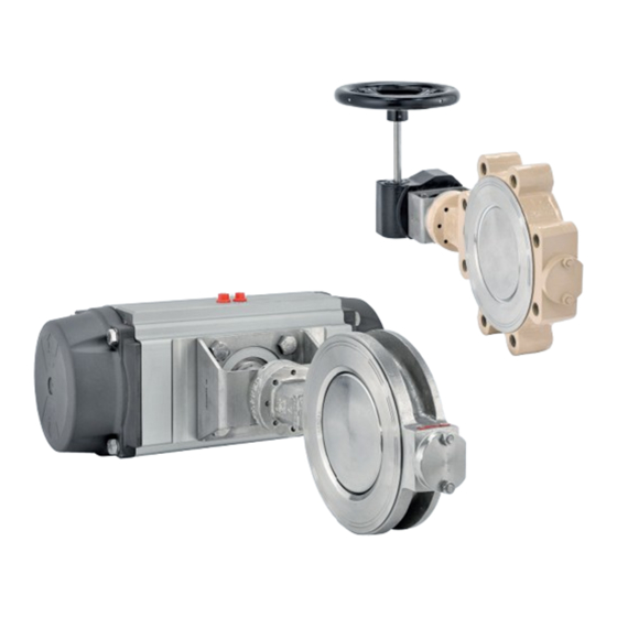
Control and shut-off valve BR 14b and BR 14c
to combine with actuators
January 2022 edition
PFEIFFER Chemie-Armaturenbau GmbH · Hooghe Weg 41 · 47906 Kempen · Germany
Phone: +49 2152 2005-0 · Fax: +49 2152 1580
sales-pfeiffer-de@samsongroup.com · www.pfeiffer-armaturen.com
Advertisement
Table of Contents

Related Manuals for Samson EB 14b


Summary of Contents for Samson EB 14b
- Page 1 MOUNTING AND OPERATING INSTRUCTIONS EB 14b Translation of the original manual Control and shut-off valve BR 14b and BR 14c to combine with actuators January 2022 edition PFEIFFER Chemie-Armaturenbau GmbH · Hooghe Weg 41 · 47906 Kempen · Germany Phone: +49 2152 2005-0 · Fax: +49 2152 1580...
- Page 2 Note regarding this installation and operating manual This Installation and Operating Manual (EB) provides guidance for safe assembly and operation. The notes and instructions in this EB are binding when handling PFEIFFER devices. The fi gures and illustrations in this EB are ex- amples and must therefore be considered as such.
-
Page 3: Table Of Contents
Content Content Safety instructions and safety measures Notes regarding possible severe personnel injury Notes regarding possible personnel injury Notes regarding possible property damage Warning notes on the device Markings on the device Butterfl y valve type plate Actuator type plate Turning direction notice sign Design and principle of operation Variants... - Page 4 Content Start-up Operation Malfunction Detecting and rectifying errors Carrying out emergency measures Servicing Periodic tests Maintenance work 9.2.1 Replacing the seal ring Ordering spare parts and consumables 10 Decommissioning 10-1 11 Removal 11-1 11.1 Removing the butterfl y valve from the pipe 11-1 11.2 Disassembling the actuator...
-
Page 5: Safety Instructions And Safety Measures
Safety instructions and safety measures − Specialist personnel in terms of this installation and operating Safety instructions and safety measures manual are persons who, on the basis of their vocational ed- ucation, knowledge and experience and knowledge of the Intended use relevant standards, are capable of evaluating the assigned The PFEIFFER butterfl... -
Page 6: Notes Regarding Possible Severe Personnel Injury
Safety instructions and safety measures − The butterfl y valve is only used as intended as described in 1.1 Notes regarding possible severe per- this chapter. sonnel injury − An actuator unit that is subsequently installed on the butterfl y valve is adapted to the butterfl... - Page 7 Safety instructions and safety measures WARNING WARNING Danger of injury due to pressurised components and escaping Hazards due to incorrect butterfl y valve use! medium! The incorrect use of the butterfl y valve can represent a hazard for Do not loosen the screw of an optional test connection while the user and cause damage to the pipe system that are then no the butterfl...
-
Page 8: Notes Regarding Possible Property Damage
Safety instructions and safety measures 1.3 Notes regarding possible property NOTE damage Damage to the seal ring or the sealing strip Turning the valve disc over 0° leads to irreparable damage to the NOTE seal ring or the sealing strip. Only operate the valve disc within the range of 0°-90°... -
Page 9: Markings On The Device
Markings on the device Markings on the device Each butterfl y valve usually has the following marking. Table 2-1: Marking on the type plate and on the body of the butterfl y valve Pos. Marking Remark Manufacturer PFEIFFER Address see Chapter “15.2 Service” Valve type BR (and number value) e.g. -
Page 10: Butterfl Y Valve Type Plate
Markings on the device 2.1 Butterfl y valve type plate Figure 2-1: Marking positions of the type plate on the butterfl y valve BR 14b / 14c 2.2 Actuator type plate See the corresponding actuator documentation. 2.3 Turning direction notice sign The turning direction is indicated on the butterfl... -
Page 11: Design And Principle Of Operation
Design and principle of operation The double-eccentric bearing design of the shaft causes the valve Design and principle of operation disc to remain in contact with the seat during opening and clos- ing only over a very small angle of rotation (see Figure 3-1). This Version reduces wear and increases the service life of the valve. -
Page 12: Additional Fi Ttings
Design and principle of operation 3.2 Additional fi ttings Info Detailed information is available in the data sheet TB 14b. Strainer PFEIFFER recommends installing a strainer in front of the butterfl y valve. A strainer prevents the solid content in the medium from damaging the butterfl... - Page 13 Design and principle of operation Figure 3-2: Sectional drawing of the BR 14b butterfl y valve with spring washer preloaded V-ring packing Table 3-1: Parts list for the BR 14b butterfl y valve with spring washer preloaded V-ring packing Pos. Designation Pos.
-
Page 14: Assembly Of Butterfl Y Valve Br 14B With Adjustable Stuffi Ng Box (Type Wns)
Design and principle of operation Push also the bonnet sealing (23) onto the bonnet in the same 3.5.1.3 Assembling butterfl y valves from way as the body sealing (13). DN 400 (NPS16) Insert the PTFE seal ring (4) or the metal seat ring including Info the corresponding graphite rings (4) into the body. - Page 15 Design and principle of operation Insert the preassembled bonnet (7) into the bearing bore in Info the body (1) and adjust with the stud bolts (16). The required torques for tightening the adjustable compression Tighten the bonnet (7) with the nuts (17) evenly and in a spacers can be found in Table 15-1.
-
Page 16: Assembly Of Butterfl Y Valves Br 14C (Br 74B) With Spring Washer Preloaded V-Ring Packing (Type Wtd And Mtd)
Design and principle of operation Drill dowel holes for connecting the switching shaft (2) and 3.5.2.2 Assembling butterfl y valves up to the valve disc (3). DN 300 (NPS10) Pin the disc and shaft with close-tolerance grooved pins (14). Insert the seal ring (4) into the body. Info Info Fit butterfl... - Page 17 Design and principle of operation Figure 3-4: Sectional drawing of the BR 14c butterfl y valve with spring washer preloaded V-ring packing Table 3-3: Parts list for the BR 14c butterfl y valve with spring washer preloaded V-ring packing Pos. Designation Pos.
-
Page 18: Note For Installation Of Actuator Elements
Design and principle of operation 3.5.4 Note for installation of actuator ele- ments NOTE Damage to the butterfl y valve due to the incorrect actuator as- sembly! Double eccentric butterfl y valves must always be closed clock- wise! Observe the turning direction when assembling an actuator. The turning direction is indicated on the butterfl... -
Page 19: Shipment And On-Site Transport
Shipment and on-site transport Shipment and on-site transport WARNING The work described in this chapter may only be performed by Danger of injury due to the tipping of the butterfl y valve! specialist personnel qualifi ed to perform the corresponding task. Observe the centre of gravity of the butterfl... -
Page 20: Lifting Points On The Body
Shipment and on-site transport Figure 4-1: Lifting points of the BR 14b butterfl y valve In the case of interruptions in work, do not leave the lifting 4.3.3 Lifting points on the body equipment suspended in the air for a long period of time. Attach the eyebolts in the fl... -
Page 21: Lifting Points On The Bracket
Shipment and on-site transport 4.3.4 Lifting points on the bracket Info Fasten a lifting sling to the bracket and the suspension ele- In the case of butterfl y valves that are delivered without an actua- ment (e.g. hook) of the crane or forklift, see Figure 4-1. tor, the valve disc is not secured to prevent it from moving. - Page 22 Shipment and on-site transport EB 14b_EN January 2022 edition Subject to technical changes...
-
Page 23: Installation
Installation Installation 5.2 Preparing for assembly The work described in this chapter may only be performed by Butterfl y valves must be handled, transported and stored with specialist personnel qualifi ed to perform the corresponding task. care, see Chapter “4 Delivery and on-site transport”. The following instructions apply additionally for butterfl... -
Page 24: Installing The Butterfl Y Valve In The Pipe
Installation WARNING DANGER Danger and damage due to high external loads on an actuator Danger due to exceeding the limits of use! unit! Exceeding the limits of use can pose a danger to the user and Actuators are not “stepladders”. cause damage to the pipe system. -
Page 25: Installing The Butterfl Y Valve
Installation Vents are screwed into the exhaust air connections of pneu- NOTE matic and electropneumatic devices to ensure that the gener- ated exhaust air can be released to the outside (protection Damage to the valve due to improper installation! against overpressure in the device). The valve disc could be damaged and the butterfl... -
Page 26: Pressure Test Of The Pipe Section
Installation At the end of installation, perform a functional test with the 5.5.4 Fail-safe position control signals: Close the signal pressure line. The butterfl y valve must close and open correctly according to Check whether the butterfl y valve moves to the fail-safe posi- the control commands. -
Page 27: Start-Up
Start-up Commissioning/recommissioning Start-up Open the butterfl y valve slowly in the pipe. Opening slowly The work described in this chapter may only be performed by prevents a sudden increase in pressure and a resulting high specialist personnel qualifi ed to perform the corresponding task. fl... - Page 28 Start-up EB 14b_EN January 2022 edition Subject to technical changes...
-
Page 29: Operation
Operation − Butterfl y valves that were delivered from the factory with an Operation actuator are precisely adjusted. The user is responsible for As soon as the commissioning/recommissioning work is com- any changes they make. plete, see Chapter “6 Commissioning”, the butterfl y valve is −... - Page 30 Operation EB 14b_EN January 2022 edition Subject to technical changes...
-
Page 31: Malfunction
Malfunction Malfunction When rectifying the faults, chapter “1 Safety instructions and safety measures” must be observed. 8.1 Detecting and rectifying errors Type of fault Possible cause Measures Leaks in the pipe connection The fl ange connection of the Tighten the fl ange screws: butterfl... -
Page 32: Carrying Out Emergency Measures
Malfunction Type of fault Possible cause Measures Increased medium fl ow rate Leakage in the closed position Close the butterfl y valve 100%. with the butterfl y valved If the butterfl y valve is in the closed position, check if the actuator clos- closed es with full torque. -
Page 33: Servicing
Servicing Servicing NOTE The work described in this chapter may only be performed by Damage to the butterfl y valve due to excessively high or low specialist personnel qualifi ed to perform the corresponding task. tightening torques! The following documents may also be required for the mainte- The butterfl... -
Page 34: Maintenance Work
Servicing Measures in the case of a negative test Test result Check the rotary movement Tighten the packing correctly. of the actuator- and switch- If the actuator- and switching shaft are ing shaft for smooth move- blocked, remove the blockage. ment. -
Page 35: Decommissioning
Decommissioning To decommission the butterfl y valve for maintenance and repair 10 Decommissioning work or for disassembly, perform the following steps: The work described in this chapter may only be performed by Close the valves upstream and downstream of the butterfl y specialist personnel qualifi... - Page 36 Decommissioning EB 14b_EN 10-2 January 2022 edition Subject to technical changes...
-
Page 37: Removal
Removal 11 Removal 11.1 Removing the butterfl y valve from the pipe The work described in this chapter may only be performed by specialist personnel qualifi ed to perform the corresponding task. Loosen the fl ange connection. Remove the butterfl y valve from the pipe, see Chapter “4.3 Transporting and lifting the butterfl... - Page 38 Removal EB 14b_EN 11-2 January 2022 edition Subject to technical changes...
-
Page 39: Repairs
Repairs 12 Repairs 12.1.2 Replacing the meshwork packing with butterfl y valve BR 14b (type WNS) If the operation of the butterfl y valve is no longer compliant or if it does not work at all, it is defective and must be repaired or re- Place the butterfl... - Page 40 Repairs Figure 12-1: Sectional drawing of a butterfl y valve BR 14b Table 12-1: Parts list of the BR 14b butterfl y valve Pos. Designation Pos. Designation Pos. Designation Valve body Bearing bush Spacer Shaft Bearing bush Spacer Valve disc Body sealing Bonnet sealing Seal ring...
-
Page 41: Replacing The Seal Ring In Butterfl Y Valves From Dn 400 (Nps16)
Repairs Loosen the nuts (17) and remove the bonnet (7). 12.4 Sending devices to PFEIFFER Remove the tension spring (19). Defective butterfl y valves can be sent to PFEIFFER for repair. Disassemble the fastening ring (5). Proceed as follows to send devices: Remove the PTFE seal ring (4) or the metal seat ring including the corresponding graphite rings (4). - Page 42 Repairs EB 14b_EN 12-4 January 2022 edition Subject to technical changes...
-
Page 43: Disposal
Disposal 13 Disposal For disposal, observe the local, national and international regulations. Do not dispose of old components, lubricant and hazardous materials with domestic waste. EB 14b_EN 13-1 January 2022 edition Subject to technical changes... - Page 44 Disposal EB 14b_EN 13-2 January 2022 edition Subject to technical changes...
-
Page 45: Certifi Cates
Certifi cates 14 Certifi cates The declaration of conformity is available on the following pages: − Declaration of conformity according to Pressure Equipment Directive 2014/68/EU for automated valves, see page 14-2. − Declaration of conformity according to Pressure Equipment Directive 2014/68/EU for manually operated valves, see page 14-3. - Page 46 Certifi cates EB 14b_EN 14-2 January 2022 edition Subject to technical changes...
- Page 47 Certifi cates EB 14b_EN 14-3 January 2022 edition Subject to technical changes...
- Page 48 Certifi cates EB 14b_EN 14-4 January 2022 edition Subject to technical changes...
- Page 49 Certifi cates EB 14b_EN 14-5 January 2022 edition Subject to technical changes...
- Page 50 Certifi cates EB 14b_EN 14-6 January 2022 edition Subject to technical changes...
-
Page 51: Annex
Annex 15 Annex Tightening torques Tightening [Nm] for sealing units Thread [mm] [bar] method 15.1 Tightening torques, lubricant and tools With a spanner 15.1.1 Tightening torques With a torque wrench With a spanner 15.1.1.1 Adjustable stuffi ng box With a torque wrench Info The required torques for tightening the adjustable compression... -
Page 52: Lubricant
Annex Table 15-4: Sealing unit B 15.2 Service Seal Nominal pressure Description For maintenance and repair work as well as malfunctions or de- With fi bre gaskets fects, contact the After Sales Service at PFEIFFER for support. Seal for tongue and and metal-reinforced groove fl... -
Page 53: Spare Parts For Butterfl Y Valve Br 14B (Type Wtd And Mtd)
Annex 15.3.1 Spare parts for butterfl y valve BR 14b (type WTD and MTD) Figure 15-1: Exploded drawing of the BR 14b butterfl y valve with spring washer preloaded V-ring packing Table 15-6: Recommended spare parts for the butterfl y valve BR 14b (type WTD and MTD) In the spare parts set for In the spare parts set for 2 year Pos. -
Page 54: Spare Parts For Butterfl Y Valve Br 14B (Type Wns)
Annex 15.3.2 Spare parts for butterfl y valve BR 14b (type WNS) Figure 15-2: Exploded drawing of the BR 14b butterfl y valve with adjustable stuffi ng box Table 15-7: Recommended spare parts for the butterfl y valve BR 14b (type WNS) In the spare parts set for In the spare parts set for 2 year Pos. -
Page 55: Spare Parts For Butterfl Y Valve Br 14C (Type Wtd And Mtd)
Annex 15.3.3 Spare parts for butterfl y valve BR 14c (type WTD and MTD) Figure 15-3: Exploded drawing of the BR 14c butterfl y valve with spring washer preloaded V-ring packing Table 15-8: Recommended spare parts for the butterfl y valve BR 14c (type WTD and MTD) In the spare parts set for In the spare parts set for 2 year Pos. - Page 56 Annex EB 14b_EN 15-6 January 2022 edition Subject to technical changes...
- Page 57 EB 14b_EN January 2022 edition Subject to technical changes...
- Page 58 EB 14b_EN January 2022 edition Subject to technical changes...
- Page 59 EB 14b_EN January 2022 edition Subject to technical changes...
- Page 60 PFEIFFER Chemie-Armaturenbau GmbH Hooghe Weg 41 · 47906 Kempen · Germany Phone: +49 2152 2005-0 · Fax: +49 2152 1580 E-Mail: sales-pfeiffer-de@samsongroup.com · Internet: www.pfeiffer-armaturen.com EB 14b_EN January 2022 edition Subject to technical changes...
Need help?
Do you have a question about the EB 14b and is the answer not in the manual?
Questions and answers