Table of Contents
Advertisement
Quick Links
MOUNTING AND
OPERATING INSTRUCTIONS
EB 29b
Translation of the original manual
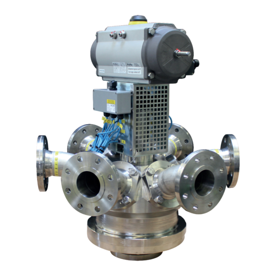
Multi-way Diverting valve BR 29b • DIN and ANSI version
to combine with actuators
for installation in piggable pipes
November 2023 edition
PFEIFFER Chemie-Armaturenbau GmbH · Hooghe Weg 41 · 47906 Kempen · Germany
Phone: +49 2152 2005-0 · Fax: +49 2152 1580
sales-pfeiffer-de@samsongroup.com · www.pfeiffer-armaturen.com
Advertisement
Table of Contents

Related Manuals for Samson EB 29b


Summary of Contents for Samson EB 29b
- Page 1 MOUNTING AND OPERATING INSTRUCTIONS EB 29b Translation of the original manual Multi-way Diverting valve BR 29b • DIN and ANSI version to combine with actuators for installation in piggable pipes November 2023 edition PFEIFFER Chemie-Armaturenbau GmbH · Hooghe Weg 41 · 47906 Kempen · Germany Phone: +49 2152 2005-0 ·...
- Page 2 Note regarding this installation and operating manual This Installation and Operating Manual (EB) provides guidance for safe assembly and operation. The notes and instructions in this EB are binding when handling PFEIFFER devices. The fi gures and illustrations in this EB are ex- amples and must therefore be considered as such.
-
Page 3: Table Of Contents
Content Content Safety instructions and safety measures Notes regarding possible severe personnel injury Notes regarding possible personnel injury Notes regarding possible property damage Warning notes on the device Markings on the device Type plate 2.1.1 Actuator type plate Material identifi cation Design and principle of operation Variants Additional fi... - Page 4 Content Start-up Operation Malfunction Detecting and rectifying errors Carrying out emergency measures Servicing Periodic tests Maintenance work 9.2.1 Replacing the seat rings and ball Ordering spare parts and consumables 10 Decommissioning 10-1 11 Removal 11-1 11.1 Removing the diverting valve from the pipe 11-1 11.2 Disassembling the actuator...
-
Page 5: Safety Instructions And Safety Measures
Safety instructions and safety measures ucation, knowledge and experience and knowledge of the Safety instructions and safety measures relevant standards, are capable of evaluating the assigned tasks and identifying possible hazards. Intended use The principle function of the BR 29b multi-way diverting valve, is Personal protective equipment to divert the medium in different directions in the piggable pipe Depending on the utilized medium, PFEIFFER recommends the... -
Page 6: Notes Regarding Possible Severe Personnel Injury
Safety instructions and safety measures It is not the responsibility of PFEIFFER and therefore when using 1.1 Notes regarding possible severe per- the diverting valve ensure that: sonnel injury − The diverting valve is only used as intended as described in this chapter. -
Page 7: Notes Regarding Possible Property Damage
Safety instructions and safety measures WARNING WARNING Danger of injury during the switching operation if performing Dangers due to use as an end fi tting! test runs on diverting valves not installed in the pipe! During normal operation, in particular with gaseous, hot and/or Do not reach into the diverting valve. -
Page 8: Warning Notes On The Device
Safety instructions and safety measures 1.4 Warning notes on the device NOTE Deviation of the breakaway and actuating forces due to Warning of moving parts non-actuation of the diverting valve! Depending on the period of time of non-actuation, the breaka- way and actuation forces can deviate considerably from the ac- tuating power data in the data sheet. -
Page 9: Markings On The Device
Markings on the device Markings on the device Each diverting valve usually has the following marking. Table 2-1: Marking on the type plate and on the body of the diverting valve Pos. Marking Remark Manufacturer PFEIFFER Address see Chapter “15.3 Service” Valve type BR (and number value) e.g. -
Page 10: Type Plate
Markings on the device 2.1 Type plate 2.1.1 Actuator type plate See the corresponding actuator documentation. 2.2 Material identifi cation The diverting valves are marked on the body with the material specifi cation, see Table 2-1. Further details can be obtained from PFEIFFER. EB 29b_EN November 2023 edition Subject to technical changes... -
Page 11: Design And Principle Of Operation
Design and principle of operation Control positions Design and principle of operation The setup position, and the control functions of the actuator are carried out using a incremental controlled coupling for position- Characteristics ing in order to be able to move to all positions. Depending on −... -
Page 12: Additional Fi Ttings
Design and principle of operation − Minimised cavity with PTFE-strips 3.5 Diverting valve assembly − Different connecting designs − With integrated pig stopper 3.5.1 Preparation of the assembly To assemble the ball valve, all parts must be prepared, e. g. the parts are carefully cleaned and placed on a soft mat (rubber mat 3.2 Additional fi... - Page 13 Design and principle of operation Fig. 3-2: Sectional drawing of the BR 29b diverting valve Table 3-2: Parts list Item Description Item Description Main body Disc spring set Ball V-ring packing Base fl ange O-ring Control shaft O-ring Side body O-ring Stuffi...
-
Page 14: Pre-Assembly Of The Main Body
Design and principle of operation After applying grease to the screws (19), tighten the fl ange Info with the main body (1) together, evenly and in alternating Pull on the disc spring jacket so that the long side of the jacket is pattern. -
Page 15: Shipment And On-Site Transport
Shipment and on-site transport Shipment and on-site transport WARNING The work described in this chapter may only be performed by Danger of injury due to the tipping of the diverting valve! specialist personnel qualifi ed to perform the corresponding task. Observe the centre of gravity of the diverting valve. -
Page 16: Lifting Points On The Body
Shipment and on-site transport Fig. 4-1: Lifting points on the diverting valve 4.3.3 Lifting points on the body Secure the sling against shifting and slipping off. Fasten the sling such that it can be removed again after in- Fasten a lifting sling to each fl ange of the housing and on the stallation in the pipe. -
Page 17: Storing The Diverting Valve
Shipment and on-site transport Lift the diverting valve carefully. Check if the load lifting equipment holds. Move the diverting valve at a constant speed to the installa- tion site. Install the diverting valve in the pipe, see chapter 5.4 After installation in the pipe: check that the fl anges are fi rmly tightened and that the diverting valve holds in the pipe. - Page 18 Shipment and on-site transport EB 29b_EN November 2023 edition Subject to technical changes...
-
Page 19: Installation
Installation When connecting the attachments, make sure that they can Installation be accessed from the operator level safely and easily. The work described in this chapter may only be performed by specialist personnel qualifi ed to perform the corresponding task. The following instructions apply additionally for diverting valves. -
Page 20: Installing The Diverting Valve In The Pipe
Installation The counterfl anges must have smooth sealing surfaces. Other WARNING shapes must be agreed upon with PFEIFFER. Danger and damage due to high external loads on an actuator DANGER unit! Actuators are not “stepladders”. Danger due to exceeding the limits of use! Loads may not be applied to the actuators as they can dam- Exceeding the limits of use can pose a danger to the user and age or destroy the diverting valve. -
Page 21: Switch Position
Installation 5.4.2 Switch position Before installing the diverting valve, check its function. 5/4-way diverting valve Depending on the function, diverting valves are supplied with the appropriate ball. The scheme for the 5/4-way diverting valve, see Fig. 5-1. Fig. 5-3: Switching positions of the 7/6-way diverting valve Top view = Actuator at the top 9/8-way diverting valve The schematic for the 9/8-way diverting valve, see Fig. -
Page 22: Checking The Assembled Diverting Valve
Installation Lift the diverting valve with suitable lifting equipment at the WARNING installation site, see chapter “4.3 Transporting and lifting the diverting valve”. Danger of injury due to escaping exhaust air! Use correct fl ange seals. During operation, when regulating or when opening and closing the diverting valve, exhaust air can escape, for example from the Clean the sealing surfaces on the diverting valve and pipe if actuator. -
Page 23: Fail-Safe Position
Installation Check the display on the position indicator. 5.5.4 Fail-safe position Close the signal pressure line. The position of the diverting valve remains in its position. EB 29b_EN November 2023 edition Subject to technical changes... - Page 24 Installation EB 29b_EN November 2023 edition Subject to technical changes...
-
Page 25: Start-Up
Start-up Commissioning/recommissioning Start-up − Open the diverting valves slowly in the pipe. Opening slowly The work described in this chapter may only be performed by prevents a sudden increase in pressure and a resulting high specialist personnel qualifi ed to perform the corresponding task. fl... - Page 26 Start-up EB 29b_EN November 2023 edition Subject to technical changes...
-
Page 27: Operation
Operation of extensions to increase the actuation torque is not permit- Operation ted. As soon as the commissioning/recommissioning work is com- − In the case of diverting valves with a hand lever, the position plete, see Chapter “6 Commissioning”, the diverting valve is of the hand lever indicates the location of the bore in the ball. - Page 28 Operation EB 29b_EN November 2023 edition Subject to technical changes...
-
Page 29: Malfunction
Malfunction Malfunction When rectifying the faults, chapter “1 Safety instructions and safety measures” must be observed. 8.1 Detecting and rectifying errors Type of fault Possible cause Measures Leaks in the pipe connection The fl ange connection of the Tighten the fl ange screws. diverting valve is leaky NOTE An excessive tightening torque when retightening the fl... -
Page 30: Carrying Out Emergency Measures
Malfunction Type of fault Possible cause Measures Problems in the actuator unit The pneumatic actuator must Disconnect the connection to the control pressure. be removed Remove the actuator from the diverting valve (observe the “Safety instructions and safety measures”, see the included actuator unit manuals). -
Page 31: Servicing
Servicing Servicing NOTE The work described in this chapter may only be performed by Damage to the diverting valve due to excessively high or low specialist personnel qualifi ed to perform the corresponding task. tightening torques! The following documents are required in addition for the mainte- The diverting valve components must be tightened with specifi... -
Page 32: Maintenance Work
Servicing Measures in the case of a negative Test test result Check the rotary movement of If the actuator- and control shaft are the actuator- and control shaft blocked, remove the blockage. for smooth movement. WARNING! If the actuator- and control shaft are blocked (e.g. -
Page 33: Decommissioning
Decommissioning To decommission the diverting valve for maintenance and repair 10 Decommissioning work or for disassembly, perform the following steps: The work described in this chapter may only be performed by Close the valves upstream and downstream of the diverting specialist personnel qualifi... - Page 34 Decommissioning EB 29b_EN 10-2 November 2023 edition Subject to technical changes...
-
Page 35: Removal
Removal 11 Removal 11.1 Removing the diverting valve from the pipe The work described in this chapter may only be performed by specialist personnel qualifi ed to perform the corresponding task. Loosen the fl ange connection. Remove the diverting valve from the pipe, see Chapter “4.3 WARNING Transporting and lifting the diverting valve”. - Page 36 Removal EB 29b_EN 11-2 November 2023 edition Subject to technical changes...
-
Page 37: Repairs
Repairs Loosen the screws (20) and remove all side bodys (5). 12 Repairs Remove seat rings (7) and disc spring (9) with disc spring If the operation of the diverting valve is no longer compliant or if jacket (10). it does not work at all, it is defective and must be repaired or re- Place the diverting valve on an even and clean work surface placed. - Page 38 Repairs − Installation drawing if available − Completed declaration regarding contamination. This form is available at www.pfeiffer-armaturen.com. Figure 12-1: Sectional drawing of the BR 29b diverting valve Table 12-1: Parts list Item Description Item Description Main body Disc spring set Ball V-ring packing Base fl...
-
Page 39: Disposal
Disposal 13 Disposal For disposal, observe the local, national and international regulations. Do not dispose of old components, lubricant and hazardous materials with domestic waste. EB 29b_EN 13-1 November 2023 edition Subject to technical changes... - Page 40 Disposal EB 29b_EN 13-2 November 2023 edition Subject to technical changes...
-
Page 41: Certifi Cates
Certifi cates 14 Certifi cates The declaration of conformity is available on the following pages: − Declaration of conformity according to Pressure Equipment Directive 2014/68/EU for automated valves, see page 14-2. − Declaration of conformity according to Pressure Equipment Directive 2014/68/EU for manually operated valves, see page 14-3. - Page 42 Certifi cates EB 29b_EN 14-2 November 2023 edition Subject to technical changes...
- Page 43 Certifi cates EB 29b_EN 14-3 November 2023 edition Subject to technical changes...
- Page 44 Certifi cates EB 29b_EN 14-4 November 2023 edition Subject to technical changes...
- Page 45 Certifi cates EB 29b_EN 14-5 November 2023 edition Subject to technical changes...
- Page 46 Certifi cates EB 29b_EN 14-6 November 2023 edition Subject to technical changes...
-
Page 47: Annex
Annex 15 Annex 15.1.1.3 Base fl ange For the assembly of the base fl ange, the screw connections are 15.1 Tightening torques, lubricant and tools tightened in a criss-cross pattern with the tightening torques indi- cated below. 15.1.1 Tightening torques Table 15-3: Base fl... -
Page 48: Lubricant
Annex Table 15-5: Sealing unit A 15.1.2 Lubricant Seal Nominal pressure Description Table 15-7: Recommended lubricant PN 10 to PN 25 Without inner eyelet Flat seal PN 40 With inner eyelet Temperature range Lubricant Shaft ring seals PN 40 are covered by this. Screws and nuts -10 ... - Page 49 Annex Fig. 15-2: Exploded drawing of the multi-way diverting valve EB 29b_EN 15-3 November 2023 edition Subject to technical changes...
-
Page 50: Service
Annex 15.3 Service For maintenance and repair work as well as malfunctions or de- fects, contact the After Sales Service at PFEIFFER for support. E-mail The After Sales Service can be reached at the e-mail address “sales-pfeiffer-de@samsongroup.com”. Necessary data Provide the following information in the case of questions and for troubleshooting: −... - Page 51 EB 29b_EN November 2023 edition Subject to technical changes...
- Page 52 PFEIFFER Chemie-Armaturenbau GmbH Hooghe Weg 41 · 47906 Kempen · Germany Phone: +49 2152 2005-0 · Fax: +49 2152 1580 E-Mail: sales-pfeiffer-de@samsongroup.com · Internet: www.pfeiffer-armaturen.com EB 29b_EN November 2023 edition Subject to technical changes...
Need help?
Do you have a question about the EB 29b and is the answer not in the manual?
Questions and answers