
Related Manuals for Pilot Communications SPM20-D


Summary of Contents for Pilot Communications SPM20-D
- Page 1 SPM20-D DC multi-channel Monitoring Unit Installation & Operation Manual V1.3 ZHUHAI PILOT TECHNOLOGY CO,.LTD.
- Page 2 Danger and warning! This device can be installed only by professionals. The manufacturer shall not be held responsible for any accident caused by the failure to comply with the instructions in this manual. Risks of electric shocks, burning, or explosion This device can be installed and maintained only by qualified people.
- Page 3 Content 1 General Information......................1 2 Order Information......................2 3 Figure and Terminals......................3 3.1 Dimension....................... 3 3.2 Installation....................... 4 4 Display and Key-press Operation..................6 4.1 General Information....................6 4.2 Light Prompt......................6 4.3 Keys Instruction...................... 6 4.4 Real-time value interface..................7 4.5 LCD display instruction..................8 4.6 Setting........................
- Page 4 6.3 Communication protocol..................16 6.4 Communication parameters................16 6.5 Communication interface to prevent strong electricity function...... 16 7 Technical Specification....................17 8 Maintenance and Trouble Shooting................19 9 Appendix.......................... 21 9.1 Terminal definition....................21 9.2 Typical wiring diagram..................22...
- Page 5 Pilot. PLbus uses daisy-chain bus topology, the connector uses the RJ12 plug, it greatly simplifies the wiring on site. SPM20-D is mainly applied to base station communication power system, it can support up to 12 measurement modules. With current, voltage, power and other parameters of the measurement and energy metering function, maximum support 63A current measurement, can meet the needs of different on-site applications.
- Page 6 But need to ensure that the total length of each measurement bus (PLbus) does not exceed 3000mm. For example:SPM20-D-M This represents a DC multi-channel monitoring unit . SPM20-D-S This represents a measuring modules.
- Page 7 3 Figure and Terminals 3.1 Dimension Unit:mm Pic 1 Measuring unit Pic 2 Measure the size of the module...
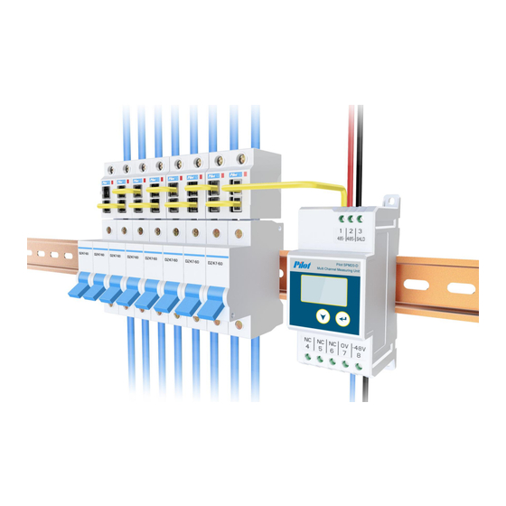
- Page 8 3.2 Installation Unit:mm Rail mounting Rail Screw mounting Screw Pic 3 Installation diagram Pic 4 Measurement module installation diagram...
- Page 9 Pic 5 Overall installation diagram Note: After SPM20-D is powered on, the RJ12 cable will carry a voltage that exceeds the safety range, DO NOT touch RJ12 cable when power on.
- Page 10 4 Display and Key-press Operation 4.1 General Information SPM20-D has a black-light LCD, Users can 48.0 query/ set different information by 2 keys according to the menu prompt. If press the keys, the back-light will be on lasting for 60s. If no continue pressing key, the back-light will be off.
- Page 11 4.4 Real-time value interface (1)Menu tree: Level 1 Level 2 Level 3 Level 4 Level 5 Level 6 Any button 10.00 480.0 1.44 return 10.00 480.0 1.44 energy voltage return 48.0 alarm current alarm module U-low info return module pass baud 9600 return...
- Page 12 4.5 LCD display instruction ■ Data Display: over voltage alarm, over current alarm, energy:Energy query measurement module fault alarm. alarm:Alarm query ①.Over voltage: Press key to enter info:Instrument information query the“voltage” page. 1. Energy query: Press any key on the main page to enter the power view page, and then page-by-page alarm...
- Page 13 3.Instrument information: In the meter ④.Measurement module fault: information page, display the Press key to enter “module” page, missing measurement module instrument wiring mode, 1 alarm, as shown below, communication port information, configured the number of error measurement modules and lost instrument version.
- Page 14 4.6 Setting ■ Instrument settings 2.Measurement module settings: SPM20-D can make the following Press key to enter the setting settings: page, as shown below。 Item Measurement unit communication Measurement module settings remove empty The user should refer to the specific...
- Page 15 remove confirm return ③.Clear all measurement modules: Press key to enter ”empty”, Clear all measurement modules, as shown below. remove all...
- Page 16 ■ Operation Example 4.Press key to enter the ID option, Address: 1, the initial password: 1, as shown below. Press key to change the address, as shown below, 1. Press key to enter the “set” page, continue press key to enter the password entry page.
- Page 17 5 Measuring performance 5.1 Real-time basic electric parameters SPM20-D can measure the voltage, current, power and other basic electrical parameters. Real-time Range Current Each circuit DC 0 ~ 63A Voltage Each circuit DC -38~ -58V Power Each circuit 0 ~ ± 5kW 5.1.1 Voltage...
- Page 18 5.3 Alarm SPM20-D has a system that alarm value can be set, and can set whether to trigger the alarm action. When the alarm event occurs, the instrument display can be switched to the alarm page, check the event type, or read the alarm type by communication.
- Page 19 RS485 terminal. Pic 9 SPM20-D RS485 6.2 Communication medium Using #22 shielded twisted-pair , it can support up to 30 SPM20-D in the same network. If there is no repeater, the longest bus can not exceed 1200 meters.
- Page 20 The communication parameters of the SPM20-D include: ◇ Meter address ID : This is identified in the network, each SPM20-D requires a unique ID. The ID can be revised. ◇ Port 1 baud rate: 4800,9600,19200 6.5 Communication interface to prevent strong electricity...
- Page 21 7 Technical Specification Rated operating parameters Parameter Range Rated power supply DC -48VDC Rated input current DC 10(63)A Electrical parameters Accuracy Parameter Range Accuracy Voltage -38--58V 0.5% Current 1-63A 0.5% Energy 0~99999999.9 1.0% Power Single Phase:0 ~ ±5kW 1.0% Operating environment Parameter Performance Operating temperature...
- Page 22 GB/T17626.5-2008 Surge immunity test (IEC61000-4-5:2005) Immunity to conducted GB/T17626.6-2008 disturbances, induced by (IEC61000-4-6:2006) radio-frequency fields Electromagnetic emission limit GB 9254-2008 value (CISPR22:2006) Voltage dips, short interruptions GB/T17626.11-2008 immunity (IEC61000-4-11:2004)
- Page 23 8 Maintenance and Trouble Shooting Possible Possible cause Possible solution problem Check if the correct working voltage The meter has has been imposed on the 0VDC and no indication The power supply fails to -48VDC terminals of the meter. after power be imposed on the meter Check if the fuse for the control supplied.
- Page 24 meter is consistent with the upper end device. The communication link Check if the 120-Ohm resistor has has not been connected been connected. to the terminal resistor. Check if the The communication link communication-shielding layer has suffers interference. been earthed effectively. The communication line Check if the communication cable is interrupted.
- Page 25 9 Appendix 9.1 Terminal definition (1)Master module Definition Description Definition Description 485+ RS485+ 485- RS485- SHLD RS485 shield None None None Power Common -48V Power -48V Measurement PLbusA module interface (2)Measurement module Definition Description Definition Description Bus interface 1 Bus interface 2...
- Page 26 9.2 Typical wiring diagram SPM20-D-5...
- Page 28 Notice: PILOT reserves the right to modify this manual without prior notice in view of continued improvement. Email: marketing@pmac.com.cn ZHUHAI PILOT TECHNOLOGY CO,.LTD. Add: No. 15, Keji 6 Road, Chuangxin Haian, Tangjia High-tech Zone, Zhuhai, Guangdong, 519085 China Tel:+86-756-3629687/3629688 Fax: +86-756-3629600/ 3629670...
Need help?
Do you have a question about the SPM20-D and is the answer not in the manual?
Questions and answers