
Related Manuals for Pilot Communications SPM32


Summary of Contents for Pilot Communications SPM32
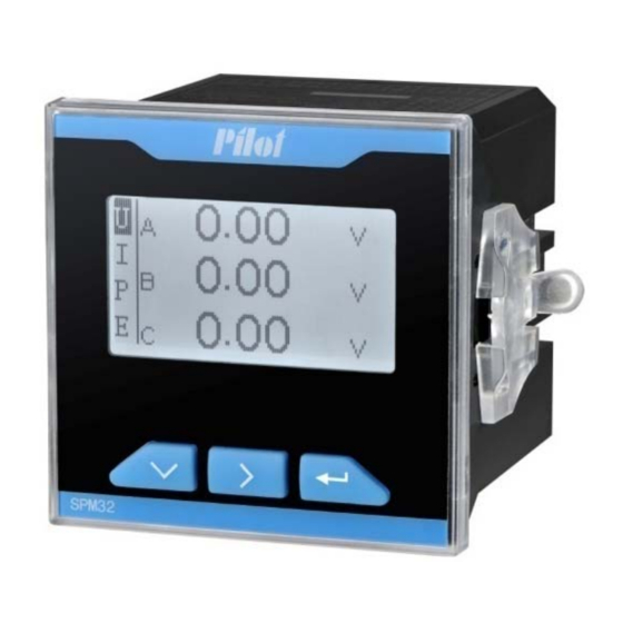
- Page 1 SPM32 Multifunctional Power Meter SPM32 Multifunction Power Meter Installation & Operation Manual V1.0...
- Page 2 Danger and warning! This device can be installed only by professionals. The manufacturer shall not be held responsible for any accident caused by the failure to comply with the instructions in this manual. Risks of electric shocks, burning, or explosion This device can be installed and maintained only by qualified people.
-
Page 3: Table Of Contents
CONTENTS 1. General Information ................4 2. Order Information ................. 5 3. Dimension and Installation ..............6 3.1 Dimension ..................6 3.2 Installation ..................6 4. Display and Keys-press Operation ............. 7 4.1 Display instruction ................ 7 4.2 Keys ..................... 7 4.3 Real-time data display procedure .......... - Page 4 5.2 Demand value ................13 5.3 Energy (kWh, kvarh) ..............14 5.4 Harmonic parameters ..............14 5.5 Unbalance parameters ............... 15 5.6 Alarm setpoint ................16 5.6.1The alarm object and type ..........16 5.6.2 Setpoint delay time ............17 5.6.3 Alarm output ..............18 5.6.4 Example ................
-
Page 5: General Information
SPM32 Multifunctional Power Meter 1. General Information SPM32 Three Phase Multifunction Power Meter is designed for monitoring and displaying all kinds of electricity parameters in high/ low voltage system to 650kV. It has one RS485 port and support Modbus-RTU communication protocol. -
Page 6: Order Information
SPM32 ① ② ①: Optional function Two relay output Two status input ②: Rated input voltage/ current Example: SPM32-SR-V1, it means the device provides basic measuring function, one RS485 port, 2 digital input, 2 relay output. Rated input current 5A. -
Page 7: Dimension And Installation
3. Dimension and Installation 3.1 Dimension unit:mm 3.2 Installation unit:mm... -
Page 8: Display And Keys-Press Operation
4. D Display and Keys-press s Operation 4.1 D Display instru uction 1: Ma ain menu, the bla ck flashing is the e current menu. 2: Pro ompt of commun ication . 3: Un it of parameter. 4: Dat ta display area. Descr ription: (1) If t... -
Page 9: Real-Time Data Display Procedure
4.3 Real-time data display procedure Main menu Sub menu Volt(ph-ph) Volt (ph-N) Frequency Zerosequencycurrent Current 3phasereactivepower 3phaseapparentpower Totalpower Active power 3phasepowerfactor Totalpowerfactor Imp.kWh/kvarh Total energy Exp.kWh/kvarh Max.demandforI DemandforP Demand current Max.demandforP DemandforPtot Max.demandforPtot THDforI 3rdharmonicforV THD for V 5thharmonicforV 7thharmonicforV 9thharmonicforV Alarm info 3rdharmonicforI... -
Page 10: Setting Menu And Procedure
4.4 Setting menu and procedure 1. Password (PASS) 10. Version info (INFO) : Default SV: Software version PASS Demo I n f o Range: 00-99 HV: Hardware version SV1.0.0 HV1.0.0 MODE ( can not set) 9. DEMO 2. CT ratio PASS "YES"... - Page 11 Remar 1. Input super password “99”, the device will display the original password. 2. In 3-phase 3-wire mode, the device displays total power only (total P, total Q, total PF). Per phase power value will be 0. 3. The optional relay function only can be set via Modbus communication 4.
-
Page 12: Measuring Capability
35 ~ 65Hz 35 ~ 65Hz 5.1.1 Voltage SPM32 maximum measurement for phase voltage is 400V (PT secondary). In 3-phase 3-wire system, maximum measurement for line voltage is 500V (PT secondary). Users should be noted this to prevent internal measuring circuit... -
Page 13: Current
5.1.2 Current SPM32 must be connected by CT to measure current. CT secondary rated output required to meet the input requirements of SPM32 rated current (5A or 1A). When using an external CT, wiring should prevent open, otherwise it will generate a higher voltage in the secondary role. -
Page 14: Power
5.2 Demand value Demand value is accumulated value during a specified period divided by the length of that period. SPM32 adopts Fix Block to calculate the demand. Fix interval is 15 minutes. SPM32 provides the following demand data and measuring ranges:... -
Page 15: Energy (Kwh, Kvarh)
The figure below describes demand calculation: 5.3 Energy (kWh, kvarh) SPM32 accumulates energy parameters: imp. kWh, exp. kWh, imp. kvarh, exp. kvarh and kVAh. If the value reaches to maximum ( 99,999,999.9 kWh), it will automatically turn over, and re-start accumulate from 0. -
Page 16: Unbalance Parameters
: Highest harmonic order, which should be 31 here. Note SPM32 LCD display 3 harmonic and THD, other order harmonic can be read via Modbus communication. 5.5 Unbalance parameters SPM32 can measure current unbalance, the unbalance is calculated: ×100% ( ) Xunbal Xmax... -
Page 17: Alarm Setpoint
5.6 Alarm setpoint SPM32 with user definable valued system which can monitor the electrical parameters of the instrument and set the action. 5.6.1The alarm object and type Object Alarm triggered remark The upper limit of Max. primary voltage > Upper limit... -
Page 18: Setpoint Delay Time
frequency 0 means unable alarm. The lower limit of Metering frequency (≠0) < Lower limit frequency The upper limit of Total active power (primary) > Upper Setting value to power limit 0 means unable alarm. Voltage phase Any one phase or 2 phase voltage Select ON/OFF loss (secondary) <10V... -
Page 19: Alarm Output
5.6.3 Alarm output When the alarm occurs, the alarms type can also be read from LCD or via Modbus communication. If the alarm associated relays, the relay generates action. Once the alarm disappears, the ALARM light will be off, the relay will be reset. -
Page 20: Input/Output Characteristics
Or, the relay can be set to remote control mode. Users can remote control the relay according to project requirement. SPM32 provides two relay operation modes. The action of relay is different in these two modes. The default control mode of this product is remote control. -
Page 21: Digital Input
(176V~300V). The following 2-way status input as example to introduce this wiring mode. ◇ External active node wiring diagram is shown as below: In general, when the external node is closed on, SPM32 LCD corresponding ● status input channel is ON ( ), internal set to 1. -
Page 22: Technical Specification
7. Technical Specification AC 85~265V Aux. power supply DC 100~300V 5A or 1A Rated input current 57V ~300V(ph-N), 35Hz~65Hz Rated input voltage Rated voltage 220V, 2 channel active status input. Status input Lower than 60V is open, higher than 178V is closed. - Page 23 Parameter Range Accuracy voltage 10V~500V 0.2% current 5%~120% of rating 0.2% Power factor -1.000~1.000 0.5% Active energy 0~99999999.9 1.0% or 0.5% Reactive energy 0~99999999.9 2.0% Per phase: 0 ~ ± 26MW Active power 0.5% Total: 0 ~ ± 78MW Reactive power Per phase: 0 ~ ±...
-
Page 24: Communication Protocol
2000V。 Rated insulation voltage≤60V,The test voltage 1000V。 Leakage current ≦ 10mA。 8. Communication protocol (Please refer to SPM32 Modbus Communication Protocol & Register List) -
Page 25: Maintenance And Trouble Shooting
9. Maintenance and Trouble Shooting Possible Possible cause Possible solution problem Check if the correct working There is no voltage has been imposed on the display on The power supply fails L/+ and N/- terminals of the device after to be imposed on the meter. - Page 26 correct. the meter. Check if the CT ratio has been set correctly. Check if the measurement mode has been set correctly. The power Check if the phase sequence measurement is not corresponding to the voltage and correct. the current is correct. Check if the current terminals of the same name are wrong.
- Page 27 The control mode of Check if the current relay is relay is not correct. under the correct mode. The communication Check if the communication baud rate of the meter baud rate of the meter is is not correct. consistent with its definition. The communication link has not been Check if the 120-Ohm resistor...
-
Page 28: Terminals Definition
10. Terminals Definition Terminals of basic unit Def. Instruction Def. Instruction Phase C current Phase C current outgoing line incoming line Phase B current Phase B current outgoing line incoming line Phase A current Phase A current outgoing line incoming line Null SHLD RS485 shield... - Page 29 Terminals of 2DI+2DO module (Optional) Def. Instruction Def. Instruction Relay 1 output 1 Relay 1 Output 2 RLN1 Relay 2 output 1 Relay 2 Output 2 RLN2 Null Null Status input 2 Status input 1 Status input public Terminals of 2DO module (Optional) Def.
-
Page 30: Typical Connection
11. Typical Connection SPM32 supports multiple connection modes of measurement, the following methods were used icons explained. 3-phase 4-wire system 3-phase3-wire system ■ 3-phase 4-wire system, no PT, 3CT... - Page 31 ■ 3-phase 4-wire system, 3PT, 3CT ■ 3-phase 3-wire system, no PT, 3CT ■ 3-phase 3-wire system, no PT, 2CT...
- Page 32 ■ 3-phase 3-wire system, 2PT, 3CT...
- Page 33 ■ 3-phase 3-wire system, 2PT, 2CT ■ Typical wiring: 3-phase 4-wire system SPM32-SR-V1 (no PT, 3 CT) Power Status Supply Input RLN1 Relay Output RLN2 Current Input Voltage Input RS485 Comm. Shield...
- Page 34 ■ Typical wiring: 3-phase 3-wire system AC 10KV SPM32-SR-V1 (3 PT, 2 CT) FU1/5A Power Status Supply Input RLN1 Relay Output RLN2 Current Input FU2、FU3、FU4/5A Voltage Input RS485 Comm. Shield...
Need help?
Do you have a question about the SPM32 and is the answer not in the manual?
Questions and answers