Table of Contents
Advertisement
Quick Links
Advertisement
Table of Contents

Related Manuals for Pilot Communications PMAC211


Summary of Contents for Pilot Communications PMAC211
- Page 1 PMAC211 Multi-channel power meter Installation & Operation Manual V1.0...
- Page 2 Danger and warning! The device should be install by qualified people The manufacturer shall not be held responsible for any accident caused by the failure to comply with the instructions in this manual. Risks of electric shocks, burning, or explosion ...
- Page 3 Note : What is the meter ID? You can find the S/N on the meter house. As picture 1-1 The last The last two numbers is the meter’s ID address. (But if the last two numbers are “00”, then use “100” as meter ID address) For example: if the S/N number is 15023876, then the meter ID is 76 If the S/N number is 15033800, the the meter ID is 100.
-
Page 4: Table Of Contents
CONTENT 1. Product Information ........................ 1 2. Technical Specification ......................2 2.1 Technical parameter ..................... 2 2.2 Measuring range and accuracy ................. 2 2.3 Electromagnetic compatibility ..................3 2.4 Working environment ....................3 3. Model Information ........................4 3.1 Order Information......................4 3.2 Accessory information .................... -
Page 5: Product Information
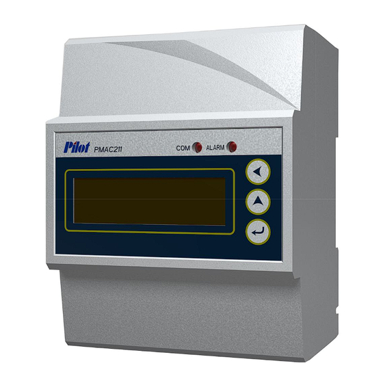
PMAC211 Multi-channel power meter can be used for monitoring low voltage electronic parameter of multi circuits, energy consumption and alarm for parameter. One PMAC211 can maximum monitor 4 three phase circuit, small size to save space, RS485 port to communication, suitable for low voltage power distribution system and energy efficiency management etc..applications. -
Page 6: Technical Specification
2. Technical Specification 2.1 Technical parameter Parameter Range Power supply AC 85~265V,DC100~300V,Power loss≤2W Rated input voltage 3×220/380V 45Hz~65Hz Rated input current Connection with standard external CT Power frequency withstand voltage 2000VAC Insulation resistance ≥ 100MΩ Insulating property Impulse withstand voltage 6000V IP index IP52(front panel),IP20 (case) -
Page 7: Electromagnetic Compatibility
2.3 Electromagnetic compatibility Item Standard Level Electrostatic discharge GB/T17626.2-2006 Level 4 immunity (IEC61000-4-2:2001) RF Electromagnetic field GB/T17626.3-2006 Level 4 radiated immunity (IEC61000-4-3:2002) Electrical fast transient GB/T17626.4-2008 Level 4 pulse group immunity (IEC61000-4-4:2006) GB/T17626.5-2008 Surge (impact) immunity Level 4 (IEC61000-4-5:2005) Radio frequency GB/T17626.6-2008 Level 3... -
Page 8: Model Information
3. Model Information 3.1 Order Information PMAC211 - □ – □ ① ② ① Number of the circuit 1 Channel 4 Channel ② Type of the current transformer 100A solid core CT(100A/100mA) LACT-100C1 100A split core CT(100A/33.3mA) LACT-100K1 3.2 Accessory information There are 2 kinds of current transformers, please refer to Chapter 4 for their appearance and dimension. -
Page 9: Product Installation
4. Product Installation 4.1 Dimension & Installation of main model Unit:mm Picture 4.1 PMAC211 Dimension 35mm DIN Raill Picture 4.2 PMAC211 Installation... -
Page 10: Dimension Of Current Transformer
4.2 Dimension of Current Transformer Black S1(黑) 主视图 Front view Red/black wire 红、黑线 黄腊管 S2(红) Schematic diagram 原理图 Vertical view 俯视图 Picture 4.3 LACT-100C1 solid core CT dimension S2(黑) Black S1(白) Picture 4.4 LACT-100K1 split core CT dimension... -
Page 11: Terminal Definition
4.3 Terminal Definition Upward View for bottom terminal Mark Definition Mark Definition Power supply Positive Phase A voltage power supply negative Phase B voltage Null Phase C voltage 485- RS485- Neutral Voltage 485+ RS485+ SHLD Communic-ation Shield... - Page 12 Top view for upper terminal Mark Definition Mark Definition circuit phase A current circuit phase A current output output circuit phase A current circuit phase A current input input circuit phase B current circuit phase B current output output circuit phase B current circuit phase B current input input circuit phase C current...
- Page 13 Mark Definition Mark Definition circuit phase A current circuit phase A current output output circuit phase A current I10* circuit phase A current input input circuit phase B current circuit phase B current output output circuit phase B current I11* circuit phase B current input input circuit phase C current...
-
Page 14: Typical Wiring
4.4 Typical wiring PMAC211 support three phase 4 wires connection mode as below picture: PMAC211 P ow er s upply V oltage S ig nal I7 * 3 rd c ircu it I8 * cu rrent input I9 * I1 *... -
Page 15: Display And Operation
5. Display and operation 5.1 Introduction for display ⑦ ⑧ Brand Model ⑨ ① ③ ② ④ ⑤ ⑥ Introduction for display: ①:Prompt for real -time data type ②:Prompt for circuit, for example: F1 means 1 circuit, F4 means 4 circuit ③:... -
Page 16: Button Introduction
5.2 Button introduction In different interface, there has different function for the same button. Configuration interface symbol Real-time Definition Modify data interface Inquiry configuration configuration Left Turn page in Move data bit button 2nd menu Turn to real-time Turn page in Plus 1 of the data Up button data display... - Page 17 1st menu 2nd menu 1st circuit 1st circuit 1st circuit 1st circuit 1st circuit 1st circuit 1st circuit Ia phase A kWh phase A kvarh 1st circuit 1st circuit 1st circuit 1st circuit 1st circuit 1st circuit 1st circuit Ib phase B kWh phase B kvarh 1st circuit...
- Page 18 Step to inquiry real-time data: When power on, display as below: Phase A voltage Press button continuously, you can see the data one after another Phase B voltage Phase C voltage Frequency Press button to enter into next menu 1st circuit phase A current...
- Page 19 Press button continuously, you can see the data one after another 1st circuit phase A active power 1st circuit phase A reactive power 1st circuit phase A apperant power 1st circuit phase A power factor 1st circuit phase A active energy 1st circuit phase A reactive energy Press button to enter into next...
- Page 20 Press button continuously, you can see the data one after another 1st circuit phase B active power 1st circuit phase B reactive power 1st circuit phase B apperant power 1st circuit phase B power factor 1st circuit phase B active energy 1st circuit phase B reactive energy Press button to enter into next...
- Page 21 Press button to enter into next menu 1st circuit total active power …… (other circuit data inquiry is the same as 1 circuit) Press button to enter into next menu (when alarm occurs, the alarm indication light will flash once per 2s) No alarm Different alarm code means different type of alarm...
- Page 22 V oltage upper limit alarm V oltage bottom limit alarm V oltage upper & bottom limit alarm C urrent upper limit alarm Voltage & Current upper limit alarm Voltage bottom limit & Current upper limit alarm Voltage upper / bottom limit & Current upper limit alarm Other 1 menu and corresponding 2...
-
Page 23: Parameter Configuration
When there has no operation in 3 minutes, the display will automatically turn to Phase A voltage interface. 5.4 Parameter configuration Below is the structure for parameter configuration interface , from real-time inquiry to parameter configuration interface:... - Page 24 Parameter setting range: Item Data range Illustration Password Initial value is 1 Communication 1~247 Initial value is 1 address Initial value is 9600bps Communication 4800bps or 9600bps 0: 4800bps; baud rate 1: 9600bps; Rated current 50~600A Default 100A Alarm action: when the value larger 0~280.0V ,...
- Page 25 Step for parameter setting: In any real-time data inquiry interface, Input password press button, enter into configuration mode Press button once, the single digit flash for enter password Press button once, to change the single digit to 1 (default password is 1 ) Set communication address Press button until it display A...
- Page 26 Press button once to modify baud rate Press botton once to confirm the new value Set voltage upper limit value 1. Press until it display U 2. Press button once , the value flash 3. Press button once to modify baud rate 4.
- Page 27 hronized updating all the three phase cir cuit current upper limit Press button to enter software version interface ( read only) Note : When there is no operation in 3 minutes, the display will automatically turn to Phase A voltage interface.
-
Page 28: Modbus Protocol
6. MODBUS Protocol PMAC211 provide RS485 communication port, MODBUS-RTU communication protocol. 8 data bit 1 stop bit No parity Please kindly refer to “PMAC211_MODBUS protocol and register list” for more detail about the register list. -
Page 29: Failure Recovery
7. Failure recovery Probably problem Probably reason Solution Check power supply Indication light no terminal input correct light on after input Power supply don’t working voltage control power connect well Check if the control power supply supply is burned Check if VN connect is OK Incorrect voltage Check if the monitored voltage is... - Page 30 Incorrect Check if the setting address is communication correct according to the definition address Incorrect Check if the setting baud rate is communication baud correct according to the definition rate Upper device can’t communication Communication link has input 120 Ω Check if with device haven’t connect with...
- Page 31 Note: PILOT reserves the right to modify this manual without prior notice in view of continued improvement. Email: overseamarket@pmac.com.cn ZHUHAI PILOT TECHNOLOGY CO., LTD. PILOT (HENGQIN) CO., LTD. Add: No. 15, Keji 6 Road, Chuangxin Haian, Tangjia High-tech Zone, Zhuhai, Guangdong, 519085 China Tel: +86 -756-3629687/ 3629688 Fax: +86-756-3629600/ 3629670...
Need help?
Do you have a question about the PMAC211 and is the answer not in the manual?
Questions and answers