Table of Contents
Advertisement
Advertisement
Table of Contents

Related Manuals for Pilot Communications SPM33


Summary of Contents for Pilot Communications SPM33
- Page 2 Danger and warning! This device can be installed only by professionals. The manufacturer shall not be held responsible for any accident caused by the failure to comply with the instructions in this manual. Risks of electric shocks, burning, or explosion This device can be installed and maintained only by qualified people.
-
Page 3: Table Of Contents
SPM33 Multifunctional power meter Contents 1.General Information ..................2. Order information ..................3. Dimension and Installation ................. 3.1 Dimension ................... 3 3.2 Installation ................... 3 4. Operation ...................... 4.1 Real-time measurement data structure ..........4 4.2 The graphic display ................5 .. - Page 4 7. Technical Datasheet .................. 8. Communication protocol ................8.1. Introduction ..................27 8.2. Detailed Description of the SPM33 Modbus Protocol ....... 28 8.2.1. SPM33 Modbus Protocol Rules ..........28 8.2.2. Modes of Transmission ............29 8.2.3. Description of the Modbus Packet Structure ......29...
- Page 5 8.3.3 Relay Control (Function Code 05H) ........36 8.3.4. Preset Multiple Registers (Function code 10H) ..... 37 8.4. Calculating the CRC-16 Error Check Field ........38 8.5. Description of SPM33 Registers............42 8.6 Description of Data Types ..............42 8.6.1 Real-time data register list ............. 43 8.6.2 List of demand data registers ..........
-
Page 6: General Information
1. General Information SPM33 three phase multi-function power meters, mainly apply to Low Voltage Distribution System, which voltage below AC400V (L-N), it can through RS485/ Modbus communication to manage instrument of network, and achieve automatic control. The main characteristics of SPM33 are as follows:... -
Page 7: Order Information
① ② ① :Feature selection Two relay alarm output ② :Rated identify measurement parameters 3×220/380V, 5A 3×220/ 380V ,1A Example: SPM33-R-V1: the low-voltage three-phase multifunction power meter, rated measuring 220/380V 5A, with standard 2 status inputs, optional 2 relay alarm output. -
Page 8: Dimension And Installation
3. Dimension and Installation 3.1 Dimension unit:mm 80.5 96.0 89.50 69.8 SPM33 ALARM 3.2 Installation unit:mm... -
Page 9: Operation
4. Operation 4.1 Real-time measurement data structure (1) Real-time measurement data display by the form of main menu、submenu: page button of main menu: page button of submenu: (2) Menu tree diagram: ① Can flip the main menu by press ② Can flip the submenu which under the main menu, by press... -
Page 10: The Graphic Display
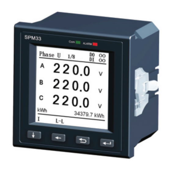
4.2 The graphic display 1 : Prompt of the currently displayed page; Phase U 2:Prompt display page number; 2 2 0 0 . 3:Status prompt of DI/DO ; 2 2 0 0 . 4:Data display area; 2 2 0 0 . 5:Energy display area;... -
Page 11: Status Inquiry
4.3 Status Inquiry (1) COM lamp, always bright when power on, blinks when there is communication. (2) ALARM lamp, flashes when there is an alarm, off when no alarm off. 4.4 Key Description Note: In a different interface, the same keys have different functions. Sibling menu switch / move the cursor to the right Switching sibling menu to submenu / move the cursor to the left Exit... -
Page 12: Parameter Settings
4.5 Parameter settings Meter Programming SPM33 ALARM 1/11 SPM33 can program the following parameters: Project programming CT values Adjustment phase 2. Communication: press key enter the communication interface, can sequence set meter mailing address and baud rate, Communication Language the figure as below. Mailing Address... - Page 13 Notice: action value of voltage upper limit SPM33 ALARM Mode 3/11 must be greater than voltage lower limit. Mode Can be set to”0”,”0”indicates that the alarm type is closed. Alarm ②Action value of voltage lower limit : 4.Alarm:Press key to enter the voltage limit alarm interface, figure as unit is V,two decimal places.
- Page 14 ④ Action value of current lower limit : Notice: action value of frequency lower limit must be less than frequency upper unit is A,one decimal places. limit. Can be set to “0”, ”0”indicates that range:1.0~60000.0A. Notice: current is the value for the primary the alarm closed.
- Page 15 Mode: You can set the remote or alarm sequence and direction, which mode. corresponding to voltage ,in accordance Reset time setting range: 0 ~ 120s. with the wiring on-site; SPM33 ALARM SPM33 ALARM Relay 1 5/11 Phase-Ad...
- Page 16 10. Password: press key to enter language setting interface, figure as Password modification interface. figure as below, the user can choose Chinese and below English languages. SPM33 ALARM Language 8/11 Language English DEMO 9.Demo:press key to enter Demo 11.
- Page 17 3.For the instrument which do not Precautions 1.when password authentication input support the relay output function, will not password "33",the display the original have the relevant settings menu; password; 4.When the data setting is invalid, the 2.when instrument work under the set is unsuccessful, restore the original three-phase three-wire mode , active parameters;...
-
Page 18: Measuring Capability
5. Measuring Capability 5.1 Real-time basic electrical parameters SPM33 provides voltage, current, power, and frequency etc. basic parameters. Real-time reading Measuring range current Each phase 0 ~ 65,000A Zero sequence 0 ~ 65,000A Degree of unbalance (%) 0 ~ 100%... -
Page 19: Voltage
5.1.2 Current SPM33 must be conducted by CT to measure current. CT secondary rated output required to meet the input requirements of SPM33 rated current (5A or 1A). When using an external CT, wiring should prevent open, otherwise it will generate a higher voltage in the secondary role In the primary excitation effect, causing no casualties or damage to equipment. -
Page 20: Frequency
SPM33 working on different measurement mode, the acquisition channel of the frequency measurement is not the same. In the triangle connection mode, SPM33 measures frequency default by AB line voltage channel ; under other modes, SPM33 measures the frequency by the A phase voltage channel. If phase A default phase, then take the C phase. - Page 21 Demand reading Measuring range Demand current Current every phase 0 ~ 65,000A Maximum peak 0 ~ 65,000A Active power Every phase 0 ~ ± 26MW Three-phase total 0 ~ ± 78MW Maximum peak of every phase 0 ~ ± 26MW Maximum peak of three-phase 0 ~ ±...
-
Page 22: Energy Parameters
5.3 Energy parameters SPM33 input and output of active and reactive energy, the maximum cumulative to 99,999,999.9, display one decimal place. When the accumulated value reaches to maximum, it will overturn automatically. 5.4 Harmonic parameters SPM33 provides optional measurement of complete 31 harmonic for voltage and current as well as their total harmonic content (THD) . -
Page 23: Unbalance Parameters
Xmin — Minimum value of the three-phase voltage or current 5.6 Alarm Setpoint SPM33 with user definable valued system which can monitor the electrical parameters of the instrument and set the action. When an alarm event occurs, the instrument panel ALARM light will flash, meanwhile, the display can be... - Page 24 Object Alarm triggered remark The upper maximum voltage value in three-phase the action value 0 limit of voltage voltage> the voltage setting upper limit indicates to close the (three-phase four-wire, voltage is phase alarm object voltage; three-phase three-wire, voltage is the line voltage) The lower limit The minimum voltage value in...
-
Page 25: Alarm Action Condition
5.6.1 Alarm action condition SPM33 generated alarm condition: the setting object meet the action conditions, and need to meet the time requirements in order to be really activated. Throughout the delay period, if the object is within the return limits, then the alarm setpoint is not activated. -
Page 26: Alarm Output
6. Input/output Characteristics 6.1 Relay output SPM33 provides two relay optional modes, relay specification is 250Vac/5A, can be used with the instrument's alarm setpoint system, to monitor relative electrical parameters whether there is more limited, and thus output breaker reasonable action (details refer to the chapter of the alarm setpoint);... - Page 27 SPM33 provides two relay operation modes. The action of relay is different in these two modes. The default control mode of this product is remote control. Users can modify to alarm control through panel relay setting or through communication. Remote control (external) - The relay is controlled by a PC or PLC by ◆...
-
Page 28: Status Input
SPM33 provides active status node, which need an external power source. The following 2-way status input as example to introduce this wiring mode. ◇ External active node wiring diagram is shown as below:... -
Page 29: Dual Source Kwh Measurement
6.3 Dual Source kWh measurement DI 1 be defined as special function (register 40207), as dual source kWh measurement function After start this function: If DI 1 with status of ON, add energy value to Grid area (register 40052-40063), on the display will show Grid. And the value also will add to register 40026-40037. -
Page 30: Technical Datasheet
7. Technical Datasheet Parameters range Rated Power Supply AC 85~265V DC 100~300V Rated input current 5A or 1A Rated input voltage 3×220/380V 35Hz~65Hz Rated Status input 220V, 2 channel active status input, less than operating Rated voltage 60V is open, more than 140V is closed,Max. parameters Input is 300V. - Page 31 case IP20 Project standard Test level Electrostatic GB/T17626.2-2006 Class 4 Discharge Immunity (IEC61000-4-2:2001) Test Radiated immunity GB/T17626.3-2006 Class 4 test (IEC61000-4-3:2002) Electrical fast GB/T17626.4-2008 Class 4 transient/burst (IEC61000-4-4:2006) immunity test Surge immunity test GB/T17626.5-2008 Class 4 (IEC61000-4-5:2005) RF field immunity GB/T17626.6-2008 Class 3 induced mass...
-
Page 32: Communication Protocol
1) Allowing setting and reading all SPM33 set-up parameters from a MODBUS Master Station. 2) Allowing reading all data measured by a SPM33 and SOE (Event log). 8.1.2 Version of Communication Protocol This document is proper for all versions of SPM33 meters. It will be declared, if any change happens later. -
Page 33: Detailed Description Of The Spm33 Modbus Protocol
8.2.1. SPM33 Modbus Protocol Rules The following rules define the protocol rules for information transfer between a MODBUS Master device and the SPM33 in a RS-485 serial communications loop. 1) All communications on the RS-485 loop conforms to a MASTER/SLAVE scheme. -
Page 34: Modes Of Transmission
6) Under any circumstance, Slave can just respond one request. 8.2.2. Modes of Transmission MODBUS protocol supports ASCII and RTU modes of transmissions. The SPM33 supports only the RTU mode of transmission with 8 data bits, no parity, and one stop bit. 8.2.3. Description of the Modbus Packet Structure... - Page 35 Slave response packet should include same function field byte as request. The Modbus functions supported by SPM33 are listed as below: Function Meaning Action Code 0x01 Read Relay Output Obtains ON/ OFF information of one or Status more relay output in SPM33 (0/1)
-
Page 36: Abnormal Responses
For detail of CRC16 parity arithmetic, please refer to Section 4 . 8.2.4. Abnormal Responses If a Modbus master device sends a non-effective command to a SPM33 or attempts to read a non-effective holding register, an exception response will be generated. -
Page 37: Broadcast Packets
SPM33 Modbus support the function code include: 01H, code 02H, 03H, 05H, and 10H. This code means the slave device receive an illegal function code, or the SPM33 receive the error command. 02 illegal function SPM33 receive the address referenced in the data field code is an invalid address. -
Page 38: Packet Communication
8.3. Packet Communication Two MODBUS functions are supported by the SPM33. The standard MODBUS protocol supports only 16-bit registers, which limit the maximum value of any measurement to 65535. Section 3.1 will describe the format of Read/ Response Packet of relay output. - Page 39 (until to the high bit of the byte). The byte count field specifies all byte num. of the data. Request Packet Response Packet (Master→SPM33) (SPM33→Master) Unit ID/ Slave 1 byte Unit ID/ Slave 1 byte...
-
Page 40: Read Holding Registers (Function Code 03H)
8.3.2. Read Holding Registers (Function Code 03H) This command packet requests that the SPM33 responds all valid registers. The value of reserved registers is 0. Request Packet Response Packet (Master→SPM33) (SPM33→Master) Unit ID/ Slave 1 byte Unit ID/ Slave address... -
Page 41: Relay Control (Function Code 05H)
Use 05 command to control the relay. Relays are addressed starting at 0 Data Field is 0xFF00, request the relay to be ON. Data Field is 0x0000, request the relay to be OFF. Request Packet Response Packet (Master→SPM33) (SPM33→Master) Unit ID/ Slave 1 byte Unit ID/ Slave address... -
Page 42: Preset Multiple Registers (Function Code 10H)
2 bytes (2 * register num.) First register data Second register data CRC check code 2 bytes This command packet allows the Master to program the SPM33 setup parameters. Note: SPM33 presume all registers are continuous from the first one. -
Page 43: Calculating The Crc-16 Error Check Field
8.4. Calculating the CRC-16 Error Check Field This section describes the procedure for obtaining the CRC-16 error check field. A packet can be considered as a continuous, serial stream of binary data (0, 1). The 16-bit checksum is obtained by multiplying the serial data stream by 216 (10000000000000000) and then dividing it by the generator polynomial x +1, which can be expressed as a binary data 11000000000000101. - Page 44 the new generator polynomial, with result stored in the16-bit register. Return to step 4. 5b) If the bit shifted out to the right is zero, return to step 4. 6) Repeat steps 4 and 5 until 8 shifts have been performed. 7) Exclusive OR the next data byte with the 16-bit register.
- Page 45 XOR polynomial 1011 1011 1111 1000 SHIFT 1 bit to the right 0101 1101 1111 1100 SHIFT 1 bit to the right 0010 1110 1111 1110 SHIFT 1 bit to the right 0001 0111 0111 1111 SHIFT 1 bit to the right 0000 1011 1011 1111 SHIFT 1 bit to the right 1010...
- Page 46 SHIFT 1 bit to the right 0011 0110 1011 1011 XOR polynomial 1001 0110 1011 1010 SHIFT 1 bit to the right 0100 1011 0101 1101 SHIFT 1 bit to the right 0010 0101 1010 1110 XOR polynomial 1000 0101 1010 1111 SHIFT 1 bit to the right...
-
Page 47: Description Of Spm33 Registers
REGISTERS having addresses 4xxxx when communicating in MODBUS protocol. According to the MODBUS Protocol, in response to a request for register 4xxxx of a particular slave device (SPM33), the MODBUS master reads register xxxx-1 from the slave (SPM33). For example register 40011 corresponds to register 10. -
Page 48: Real-Time Data Register List
8.6.1 Real-time data register list Regist Read/w Definition Data Description rite Type addres attribut 40001 Phase A voltage UINT16 Secondary side L-N voltage, Calculation 40002 Phase B voltage factor: 0.01, Phase C voltage 40003 unit: V 40004 Line AB voltage UINT16 Secondary side L-L voltage, Calculation... - Page 49 Total active power high power. Calculation factor: word 0.1, unit: W. If use CT, then customers need to 40012 multiply by CT ratio. LINT32 Total reactive power low Secondary side reactive 40013 word power. Calculation factor: 0.1, unit: var. If use Total reactive power high CT, then customers need word...
- Page 50 factor: 0.1, unit: W. If use Phase B reactive power 40020 CT, then customers need to multiply by CT ratio. Phase C reactive power Only when it is 3 phase 4 wires connection mode 40021 can the value valid. INT16 Calculation factor: 0.001.
- Page 51 Input active energy low LUINT3 Calculation factor: 0.1, 40030 word unit: kWh Range: 0-99,999,999.9 Input active energy high word 40031 Output active energy low LUINT3 Calculation factor: 0.1, 40032 word unit: kWh Range: 0-99,999,999.9 Output active energy high 40033 word Input reactive energy low LUINT3 Calculation factor: 0.1,...
- Page 52 D1 means 2 channel 0 means off Relay status 40039 1 means on Alarm status WORD1 1 means alarm, 0 means no alarm Bit 1: over voltage Bit 2: under voltage Bit 3: over current 40040 Bit 4: under current Bit 5: Frequency too high Bit 6: Frequency too low Bit 7: over load...
- Page 53 Average line voltage Calculation factor: 0.01, 40044 unit: V Average phase current UINT16 Calculation factor: 0.001, 40045 unit: A Current unbalance rate Calculation factor: 0.001 40046 40047 Phase A apparent power UINT16 Calculation factor: 0.1, unit: VA 40048 Phase B apparent power 40049 Phase C apparent power Total apparent power low...
- Page 54 calculator factor 0.1, unit: kWh First is low byte, second is high byte 40055 Range: 0-99,999,999.9 40056 Grid total Active Power Primary measurement Power, calculator factor 0.1, unit: kWh First is low byte, second is high byte 40057 Range: 0-99,999,999.9 40058 Grid Input Reactive Power Primary measurement Power,...
- Page 55 Range: 0-99,999,999.9 40064 Generator Input Active Primary measurement Power, Power calculator factor 0.1, unit: kWh First is low byte, second is high byte 40065 Range: 0-99,999,999.9 40066 Generator Output Active Primary measurement Power, Power calculator factor 0.1, unit: kWh First is low byte, second is high byte 40067 Range: 0-99,999,999.9 40068...
- Page 56 Power calculator factor 0.1, unit: kvarh First is low byte, second is high byte 40073 Range: 0-99,999,999.9 40074 Generator total Reactive Primary measurement Power, Power calculator factor 0.1, unit: kvarh First is low byte, second is high byte 40075 Range: 0-99,999,999.9 Ferroelectric fault register Factory using 0: Normal...
-
Page 57: List Of Demand Data Registers
8.6.2 List of demand data registers Regist Read Definition Data Description /write type addres attrib 40701 Phase A current demand UINT16 Calculation factor: 0.001, unit: A 40702 Phase B current demand 40703 Phase C current demand 40704 Phase A active power demand UINT16 Calculation factor: 0.1, unit: W... - Page 58 demand UINT16 0.1, unit: W Maximum phase B active power 40713 demand Maximum phase C active power 40714 demand Total active power demand LUINT3 Calculation factor: 40715 low word 0.1, unit: W Total active power demand 40716 high word 40717 Phase A reactive power demand 10 times, unit: var 40718...
- Page 59 40725 Total apparent power demand 10 times, unit: VA 40726 Phase A reactive power Maximum 10 times, unit: var 40727 demand Phase B reactive power Maximum 10 times, unit: var 40728 demand Phase C reactive power Maximum 10 times, unit: var 40729 demand 40730...
-
Page 60: List Of Harmonic Data Registers
8.6.3 List of harmonic data registers Data d/wr type Register Definition Description address attri bute 40801 Va - THD UINT16 Calculation factor: 0.001 Vb - THD 40802 40803 Vc - THD 40804 Ia – THD UINT16 Calculation factor: 40805 Ib – THD 0.001 40806 Ic –... - Page 61 40809 … -40835 40836 31st harmonic component of Va 40837 2nd harmonic component of Vb UINT16 40838 3rd harmonic component of Vb Calculation factor: 0.001, Unit: % 40839 … -40865 40866 31st harmonic component of Vb 40867 2nd harmonic component of Vc UINT16 40868 3rd harmonic component of Vc...
- Page 62 40926 31st harmonic component of Ia 40927 2nd harmonic component of Ib UINT16 40928 3rd harmonic component of Ib Calculation factor: 0.001, Unit: % 40929 … -40955 40956 31st harmonic component of Ib 40957 2nd harmonic component of Ic UINT16 Calculation factor: 0.001, Unit: % 40958...
-
Page 63: List Of Configuration Registers
8.6.4 List of configuration registers Register R&W Definition Description address attribute 40201 Communication Address 1--247 40202 CT ratio 1--10000 Connection mode 0--1 phase wire 40203 : 1:3 phase 3 wire 40204 Reserved Read only 40205 Reserved Read only 0--1 0:4800 40206 Baud rate 1:9600... - Page 64 Default 1, 1 forward current Current Channel of 1 Voltage mapping 1 means 1 forward current 2 means 2 forward current 40210 3 means 3 forward current 0x8001 means 1 reverse current 0x8002 means 2 reverse current 0x8003 means 3 reverse current Default 2, 2 forward current...
- Page 65 Current Channel of 3 2 means 2 forward current Voltage mapping 3 means 3 forward current 0x8001 means 1 reverse current 0x8002 means 2 reverse current 0x8003 means 3 reverse current 0—1, default 0, remote 40213 Working status of relay 1 0 means remote control 1 means auto alarm Default 0...
- Page 66 40218 Reserved 40219 Reserved 40220 Reserved Operation value of Calculation factor: 0.01, Unit:V 40221 voltage upper limit 0 means closed For 110V – 500V, default 0. Action time of voltage 0-120s。 40222 upper limit Operation value of Calculation factor: 0.01, Unit:V 40223 voltage lower limit 0 means closed...
- Page 67 word) Action time of voltage 0-120s 40227 upper limit Operation value of Primary value of current. 40228 current lower limit (low Calculation factor: 0.1, Unit: A word) 0 means closed 1.0A-60000.0A Operation value of 40229 current lower limit (high word) Action time of voltage 0-120s 40230...
- Page 68 Operation value of Calculation factor: 0.01, frequency lower limit Unit: Hz 40233 0 means closed 45Hz – 65Hz Action time of frequency 0-120s 40234 lower limit Operation value of active Primary side value 40235 power upper limit (low Calculation factor: 0.1, word) Unit: kW 0.1-40000.0kW...
-
Page 69: Register For Command And Clear Energy
When phase A, phase B and phase C all < 110V, it means work normal. Alarm status 0 means closed 40239 1 means open. Note: Register 40221—40239 should be set once time. What’s more, the upper limit must higher than lower limit. 8.6.5 Register for command and clear energy Register Read/write... -
Page 70: List Of Device Information Registers
40259 energy Unit: kvarh 40260 Output reactive energy 40261 Note: Register 40254~40261 should be read /write once time 8.6.6 List of device information registers Register Read/write Definition Description address attribute 49001 Device No. 49002 49003 Recover user system Write 888 49004 Recover factory setting Write 888... -
Page 71: Maintenance And Trouble Shooting
9. Maintenance and Trouble Shooting Possible Possible cause Possible solution problem Check if the correct working voltage There is no has been imposed on the L/+ and N/- display on device The power supply fails to terminals of the meter. after impose be imposed on the meter. - Page 72 Check if the CT ratio has been set correctly. Check if the measurement mode has been set correctly. Check if the phase sequence The power measurement corresponding to the voltage and the is not correct. current is correct. Check if the current terminals of the same name are wrong.
- Page 73 is not correct. correct mode. The communication baud Check if the communication baud rate rate of the meter is not of the meter is consistent with its correct. definition. The communication link Check if the 120-Ohm resistor has has not been connected been connected.
-
Page 74: Appendix 1
10. Appendix 1 10.1 Terminals Definition Definiti Definition Instruction Instruction Positive pole of Null power supply Negative pole of Null power supply Status input 1 Status input 2 Status input Relay 1 output public GND Relay 2 Output RLN1 Relay 1 Output 2 RS485 485 positive RLN2... - Page 75 10.2 Typical Connection SPM33 supports multiple connection modes of measurement, the following methods were used icons explained. Vector of three-phase four-wire Vector of three-phase three-wire system system ■ three-phase four-wire system:...
- Page 76 ■ three-phase three-wire system,3CT: ■ three-phase three-wire system,2CT:...
- Page 77 SPM33 typical wiring diagrams, comprehensive electrical parameters measuring under three-phase four-wire mode, with digital status inputs and one RS485 communication function:...
- Page 78 Notice: PILOT reserves the right to modify this manual without prior notice in view of continued improvement. Technical Consulting: +86 15916202620 After-sale Services: +86 15916202800 Email: pilot006@pmac.com.cn Zhuhai Pilot Technology Co., Ltd. Add: No. 15, Keji 6 Road, Chuangxin Haian, Tangjia High-tech Zone, Zhuhai, Guangdong, 519085 China Tel: +86 -756-3629926 Fax: +86-756-3629600/ 3629670...
Need help?
Do you have a question about the SPM33 and is the answer not in the manual?
Questions and answers