
Related Manuals for Pilot Communications PMAC615


Summary of Contents for Pilot Communications PMAC615
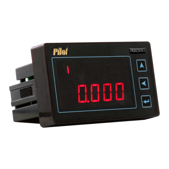
- Page 1 PMAC615 Single Phase Digital Panel Meter Installation & Operation Manual V1.0 ZHUHAI PILOT ELECTRONICS CO., LTD.
- Page 2 Danger and warning! This device can be installed only by professionals. The manufacturer shall not be held responsible for any accident caused by the failure to comply with the instructions in this manual. Risks of electric shocks, burning, or explosion ...
-
Page 3: Table Of Contents
CONTENTS 1. Product Description....................4 2. Installation and Connection..................6 3. Order Information....................... 9 4. Measurement Performance..................10 5. Operation........................13 6. Input/ Output Characteristics................. 18 7. Setpoint Alarm......................20 8. Communication Protocol..................22 9. Maintenance and Trouble Shooting..............29 10. Technical Datasheet....................31... -
Page 4: Product Description
PMAC615 digital panel meter integrates sampling and control function, which is suitable for various low voltage single phase system. PMAC615 digital panel meter provides an optional RS485 communication port to link with PLC, PCs and SCADA system. Users can program the parameter via RS485 COM easily. - Page 5 1.2 Features The main features of PMAC615 are below: Accept standard CT input ◆ Direct connect to max. 400V voltage system ◆ Active energy accuracy is in accordance with IEC62053-21, class 1 ◆ Accuracy of voltage and current measurement is 0.2% ◆...
-
Page 6: Installation And Connection
2. Installation and Connection 2.1 Environment Operating temperature: -20℃ - +60℃ Storage temperature: -30℃ - +70℃ Humidity: 5% - 90%RH, non-condensing 2.2 Dimension... - Page 7 2.3 Terminals Instruction Mark Definition Null line Live line Current negative pole Current positive pole Voltage negative pole Voltage positive pole 485+ RS485 positive pole 485- RS485 negative pole Status input 1 positive pole Status input 1 negative pole Status input 2 positive pole Status input 2 negative pole Relay output positive pole Relay output negative pole...
- Page 8 2.4 Connection Example: PMAC615-I-SRC single phase digital current meter, provides one RS485, two status input and one replay output. Power Supply Status Input Relay To control loop Current Output Signal Communication...
-
Page 9: Order Information
1. Default rated current is 5A. Other customized feature is available, please mention requirement when place order. 2. Reactive power and power factor can be read via RS485 COM only Example: In case the model number is PMAC615-I-S, the corresponding feature is measuring current, providing two status input, rated current is 5A. -
Page 10: Measurement Performance
Active Energy 0 - 99,999,999.9 kWh Note: The value of reactive power and power factor is read from RS485 COM. 4.2 Symbol of Power Factor The measurement of power factor symbol by PMAC615 is according to IEC standard, as follow instruction:... - Page 11 Quadrant 3 Quadrant 4 4.3 Energy Parameter PMAC615 provides measurement of bidirection active energy, up to 99,999,999.9 kWh. Due to the limitation of LED window size, the meter displays one energy data into two times. It firstly displays the 5 digit and above in front of decimal point, secondary displays the rest below thousand’s digit (include thousand’s digit).
- Page 12 The sheet below describes the interrelationships of various types of energy and the symbolic relationships between energy and power: First-quadrant Positive inductive active power active energy Input active energy Fourth-quadrant Positive capacitive active power active energy Second-quadrant Negative capacitive active power active energy output active energy Third-quadrant...
-
Page 13: Operation
5. Operation 5.1 Display Display instruction A: Communication prompt B: Data area C: Status input prompt D: Programming menu prompt E: Real-time parameter data 1: Logo 2: Model No. Key-press instruction: the function of every key vary with interface. Data display interface Programming interface Configure viewing Configure... - Page 14 The initial power-up interface of the meter is shown as follow: Voltage Press key continuously, it displays measurement data one by one. Current Press key once, it displays measurement value of current Active Power Press key once, it displays measurement value active power.
- Page 15 Active Energy ≥ 10000’ digit, with a mark “H” Press key once, it displays measurement value active energy, firstly displays the data above 10000’ digit. Active Energy <10000’ digit Press key once, it displays the active energy value in 1000’ digit.
- Page 16 Set CT ratio(Current Transformer) Press key until to CT character. Press key , a cursor appears. Press key , change the value. Press key , confirm the new value, the cursor disappears. Set Communication Address Press key until to ID character. Press key , a cursor appears.
- Page 17 Set the displaying of energy Press key until to “E-“ character. Press key , a cursor appears. Press key , select 0, 1 or 2. Press key , confirm the selection, the cursor disappears. “0” means to display input active energy, “1”...
-
Page 18: Input/ Output Characteristics
6. Input/ Output Characteristics 6.1 Status Input PMAC615 provides two status input channels, which are used to detect state information such as breaker position signal and isolator position signal. There is no power provided from the device. When local application requires the status input to detect signal, it should be connect to an external 220VAC/ DC power supply. - Page 19 6.2 Relay Output PMAC615 provides two relay operation modes. They are remote control and local control. Users shall distinguish the relay is in local control mode or in remote control mode. In different mode, the operation to relay is different.
-
Page 20: Setpoint Alarm
7. Setpoint Alarm PMAC615 provides one relay alarm output which is programmable. When the relay output is set to in local control mode, it indicates corresponding set point alarm. There are 5 parameters may be set under setpoint alarm feature. - Page 21 Operation upper limit: 120 Operation lower limit: 80 (Assumed that, when voltage is lower than 80% of rating, it is undervoltage. ) Operation time: 0s Return time: 0s Other values can be set according to above mentioned procedure, and the relating programming is not described here one by one.
-
Page 22: Communication Protocol
8. Communication Protocol 8.1 Overview PMAC615 supports the MODBUS-RTU communication protocol, 8 data bits, 1 stop bit, without check bit. Each frame data package contains the address field, functional code field, data field, and check field. The maximum length of each data package is 45 bytes. - Page 23 Send sexadecimal FF 00 to close the relay. Send sexadecimal 00 00 to release the relay. All other value is invalid. Control relay format Response format (master→PMAC615) (PMAC615→ master) Slave address 1 byte Slave address 1 byte...
- Page 24 The functional code is 03H. The master can read one or more than one register value, and the register return value which not defined are 0. Read register format Response format (master→PMAC615) (PMAC615→ master) Slave address 1 byte Slave address 1 byte...
- Page 25 Bit 0 means “cut off”, and bit 1 means “ close on” 8.7 Calculation Factor Because these is a limit of value, many of data registers of PMAC615 use the calculation factor. It means that, if Users want to obtain the actual value, the value should be multiplied by the corresponding calculation factor.
- Page 26 892 at this moment, the actual value if current power factor is 892 × 0.001 = 0.892. 8.8 Communication Value and Actual Value To ensure that the meter keeps adequate accuracy bits when transmitting data, some of real-time data registers of PMAC615 adopt some special methods, shown as following sheet: Content...
- Page 27 D0 means S1 channel, D1 means S2 channel. 0 40007 Status channel means cut off, 1 means closed. 40008 Relay channel 0 means cut off, 1 means closed. Total active energy 40009 low word Calculation factor is 0.1. Total value of import and export energy.
- Page 28 Range: 1~9999 Communication 40202 Range: 1 ~ 247 address 40203 Baud rate 0 means 4800bps, 1 means 9600bps 40204 Clear energy WO, write 0x00FF to clear energy. 0: Display import active energy Select the display 40205 1: Display export active energy of energy 2: Display total active energy 40206...
-
Page 29: Maintenance And Trouble Shooting
Write FF00 to close on the relay, write 0 to release the Relay control command relay. 9. Maintenance and Trouble Shooting Possible Possible Reason Possible Solution Problem Check if the correct working voltage has The meter has no indication The power supply fails to been imposed on the L/+ and N/- terminals after a control be imposed on the... - Page 30 correct. Check if the phase sequence corresponding to the voltage and the current is correct. Check if the current terminals of the same name are wrong. Check if the types of external nodes match There is no The on-off operating change in the the rated parameters of the meter.
-
Page 31: Technical Datasheet
correct. The communication link Check if the 120-Ohm resistor has been has not been connected connected. to the terminal resistor. The communication link Check if the communication-shielding suffers interference. layer has been earthed effectively. The communication line Check if the communication cable has is interrupted. - Page 32 Environment Operating -20℃ - +60℃ Temperature Storage -30℃ - +70℃ Temperature Relative Humidity 5% - 90%RH, non-condensing Electrostatic Discharge Immunity Test IEC 61000-4-2,Level 4 Radiated immunity test IEC 61000-4-3,Level 3 Electrical fast transient/burst immunity test IEC 61000-4-4,Level 4 Surge immunity test (1, 2/50μs~8/20μs) IEC 61000-4-5,Level 3 Conducted emissions EN 55022,Class B...
- Page 33 Notice: Zhuhai Pilot Electronics reserves the right to modify this manual without prior notice in view of continued improvement. Technical Consulting: +86 15916202620 After-sale Services: +86 15916202800 Email: pilot166@pmac.com.cn Zhuhai Pilot Electronics Co., Ltd. Add: No. 15, Keji 6 Road, Chuangxin Haian, Tangjia High-tech Zone, Zhuhai, Guangdong, China-519085 Tel: +86 -756-3629687/ 3629688 Fax: +86-756-3629600/ 3629670...
- Page 34 http://www.pmac.com.cn...
Need help?
Do you have a question about the PMAC615 and is the answer not in the manual?
Questions and answers