Table of Contents
Advertisement
Quick Links
Advertisement
Table of Contents

Related Manuals for Pilot Communications PMAC770H


Summary of Contents for Pilot Communications PMAC770H
- Page 1 PMAC770H Power Meter Installation & Operation Manual (Ver. 0.1 draft)
-
Page 2: Safety And Precautions
Safety and precautions Dangers and warnings This equipment should only be installed by professionals. The manufacture shall not be responsible for failures caused by non-compliance with the instructions in this manual. Precautions After removing the package of the equipment, please read this manual carefully ... -
Page 3: Table Of Contents
Contents Chapter 1. Overview ..........................6 Chapter 2. Product model ........................9 Chapter 3. Installation and wiring ....................10 3.1 Using environment ......................10 3.2 Dimensions and installation diagrams ................10 3.3 Terminal diagram .........................12 3.3.1 Main body terminals definition ................12 3.3.2 Expansion module terminals definition ..............14 3.4 Wiring ............................22 3.4.1 Power supply ...................... - Page 4 4.1.8 Frequency ......................... 28 4.2 Power quality analysis function ..................29 4.2.1 Voltage deviation ......................29 4.2.2 Frequency deviation ....................29 4.2.3 Harmonic ........................30 4.2.4 Imbalance and sequence components measurement ........31 4.2.5 Voltage flicker ......................32 4.2.6 Voltage swell, sag and interruption ............... 32 4.2.7 K factor ........................
- Page 5 4.11 Relay output ........................42 4.12 Analog output ........................42 4.13 Communication ........................42 4.14 Timing ..........................43 4.15 Store function ........................43 4.16 Real-time waveform ......................43 Chapter 5. Display and settings ...................... 44 Button ..........................44 Indicator light .........................44 5.3 Settings and display ......................44 5.3.1 Basic measurement ....................
-
Page 6: Chapter 1. Overview
With above features PMAC770H can meet the S level of power quality monitoring standard. Accurate fault diagnosis and positioning functions, for local abnormalities or local faults in the power supply and consumption system. - Page 7 function Forecast demand Slip/Fixed Extreme demand Historical extreme demand Multi-tariff ■ Waveform sampling cycle 256 points/cycles Harmonic 63rd Voltage deviation ■ Frequency deviation ■ Power Imbalance ■ quantity Sequence components ■ analysis Flicker analysis ■ Voltage ■ swell/sag/interruption Rapid voltage change ■...
- Page 8 Max 11 digital inputs 3 active switches(DI) are equipped Digital input(DI) as standard(rate input 220V±35%) 8 DI are optional (active or passive switch can be selected) Max 6 relay outputs Relay output(RO) 2 RO are equipped as standard ...
-
Page 9: Chapter 2. Product Model
Chapter 2. Product model Order information: Model:PMAC770H-①-②-③ expansion module 1 None this module 4 active DI(rated input 220V±35%) 4 passive DI(rated input 30VDC) 2 RO 2 AO(4~40mA) expansion module 2 None this module 4 active DI(rated input 220V±35%) 4 passive DI(rated input 30VDC) -
Page 10: Chapter 3. Installation And Wiring
Chapter 3. Installation and wiring 3.1 Using environment Hole size(mm) 90.00×90.00(﹢0.80) Dimensions(mm) (L*W*H) 96.00×96.00×45.1(without expansion module) 96.00×96.00×66.6(with expansion module) IP level Front panel:IP52,side & back:IP30 Measuring mode 3P4W,3P3W Working temperature -20℃~+60℃ Storage temperature -40℃~+85℃ Relative humidity 5%~95%,no condensation 3.2 Dimensions and installation diagrams Without expansion module... - Page 11 With expansion module Dimensions diagram Installation diagram...
-
Page 12: Terminal Diagram
3.3 Terminal diagram 3.3.1 Main body terminals definition Back view Mark Definition 220VAC neutral wire/220VDC negative pole 220VAC phase wire/220VDC positive pole 485- RS485A(-) 485+ RS485A(+) - Page 13 RL21 RO_1 RL22 RO_2 RL11 RO_1 RL12 RO_2 Digital input common poit(-) DI(+) DI(+) DI(+) Ia(+) Ia(-) Ib(+) Ib(-) Ic(+) Ic(-)
-
Page 14: Expansion Module Terminals Definition
3.3.2 Expansion module terminals definition Back view Expansion module installation diagram... - Page 15 3.3.2.1 SW module definition SW : active digital input Support being installed under 1 or 2 expansion module expansion module position Mark Definition PIN1 digital input EX S4 PIN2 digital input EX S5 PIN3 digital input EX S6 PIN4 digital input EX S7 PIN5 Common point...
- Page 16 3.3.2.2 SD module definition SD : passive digital input Support being installed under 1 or 2 expansion module expansion module position Mark Definition PIN1 digital input EX S4 PIN2 digital input EX S5 PIN3 digital input EX S6 PIN4 digital input EX S7 PIN5 Common point...
- Page 17 3.3.2.3 R module definition R : relay output Support being installed under 1 or 2 expansion module expansion module position Mark Definition PIN1 relay output_1 EX RL31 PIN2 relay output_2 EX RL32 PIN3 Null PIN4 relay output_1 EX RL41 PIN5 relay output_2 EX RL42 expansion module position...
- Page 18 3.3.2.4 AO module definition AO : analog output(4~20mA) Support being installed under 1 or 2 expansion module expansion module position Mark Definition PIN1 AO_1 EX AO11 PIN2 AO_2 EX AO12 PIN3 Null PIN4 AO_1 EX AO21 PIN5 AO_2 EX AO22 expansion module position PIN1 AO_1...
- Page 19 3.3.2.5 EP module definition EP:electrical energy pulse output Only support being installed under 2 expansion module Mark Definition PIN1 Active energy pulse output(+) EX P1+ PIN2 Active energy pulse output(-) EX P1- PIN3 Null PIN4 Reactive energy pulse output(+) EX P2+ PIN5 Reactive energy pulse output(-) EX P2-...
- Page 20 3.3.2.6 C module definition C:RS485 communication module Only support being installed under 3 expansion module Mark Definition PIN1 Null PIN2 Null PIN3 Null PIN4 RS485 - EX 485- PIN5 RS485 + EX 485+...
- Page 21 3.3.2.7 LAN module definition LAN:Ethernet module Only support being installed under 3 expansion module Mark Definition RJ45 RJ45 RJ45 Ethernet port...
-
Page 22: Wiring
N/-. While powered by DC power system, positive pole connected to L/+, negative pole connected to N/-. 3.4.2 Voltage & current wiring PMAC770H supports multiple wiring modes, show as below 3P4W vector diagram 3P3W vector diagram ■ 3P4W,no PT,3CT:... - Page 23 I1+ I1- I2+ I2- I3+ I3- V1 V2 V3 VN I1+ I1- I2+ I2- I3+ I3- V2 V3 VN ■3P3W, 2PT,3CT: ■3P3W, 2PT,2CT: I1+ I1- I2+ I2- I3+ I3- V1 V2 V3 VN I1+ I1- I2+ I2- I3+ I3- V1 V2 V3 VN ■...
-
Page 24: Communication Wiring
(2)Ethernet interface equips with RJ-45 connector and 10/100M port.(Suitable for "-LAN" models) 3.4.4 Digital input wiring PMAC770H provides 11 digital inputs (marks as SI1~S11) at maximum to monitor switch/breaker position signal, there are passive DI and active DI can be selected as per requirement. -
Page 25: Relay Output Wiring
3.4.5 Relay output wiring PMAC770H provides 6 relay outputs (marks as RO1~RO6) at maximum, all are normal open(NO) relays, can be used to cut off load of 250VAC/5A or 30VDC/5A or 220VDC/0.2A, an intermediate relay is recommended when the load current is large. -
Page 26: Chapter 4. Technical Features Introduction
4.1.2 Voltage PMAC770H can be used as direct connect when the measured phase voltage is lower than 398V or line voltage is lower than 690V, it shall work with PT when input voltage is larger than above value. -
Page 27: Current
PMAC770H shall work with external CT for current measuring, and the secondly value of the CT shall be 5A to connect to PMAC770H, please avoid open circuit when doing CT wiring, as this may damage the device, most importantly this may bring danger to installation... -
Page 28: Apparent Power
AB as default, if line AB is phase loss then takes from line CA, if both line AB and line CA are loss then the value will be 0. Under other wiring mode, PMAC770H will take frequency sample from phase channel (A/B/C). -
Page 29: Power Quality Analysis Function
: i-th 10 points/cycles RMS value rms-over,i PMAC770H calculates the voltage deviation according to the requirements of GB/T12325-2008 standard, the voltage measurement accuracy of the device is 0.1%,it can achieve continuous voltage deviation monitoring and alarm recording for power system. -
Page 30: Harmonic
Frequency deviation = actual frequency – nominal frequency PMAC770H has a frequency measurement accuracy of ±0.01Hz , enabling it can achieve continuous frequency monitoring, and it equips over limit alarm and recording features as well. -
Page 31: Imbalance And Sequence Components Measurement
Voltage imbalance rate √ √ √ √ √ √ 0~100% S class 4.2.3.2 Fundamental wave parameters measurement PMAC770H provides complete fundamental data for power system running status analysis Phase A Phase B Phase C Total Neutral line Phase voltage √ √... -
Page 32: Voltage Flicker
(2) Zero sequence imbalance of voltage and current 4.2.5 Voltage flicker The voltage flicker measurement range of PMAC770H is 1~20, its calculation mode is based on the IEC61000-4-15 standard, can fully meet the requirements. 4.2.6 Voltage swell, sag and interruption... -
Page 33: Voltage Crest Factor
4.2.8 Voltage crest factor PMAC770H supports voltage crest factor measurement and this can be checked over Modbus register list. The crest factor is the ratio of the load’s crest voltage to the RMS voltage, the normally crest value for most electronic device is 1.4 . -
Page 34: Electrical Energy Measurement Function
√ 4.3.2 Electrical energy overturn and clear The max electrical energy that PMAC770H can record is 99999999.999, when the actual electrical energy is larger than that, then the device will overturn the energy to zero and record further, energy clear operation can be done over Modbus register list. - Page 35 cannot be modified. When setting to 0xFFFF or other non-existent date, then it will be judged as invalid date. If any time zone in the counting solution has been set to 0xFFFF, then all dates after the time zone should be set to 0xFFFF. The time zone setting rule is the later time zone date should be later than the date of previous time zone, except for all the later time zone have been set to 0xFFFF.
-
Page 36: Historical Electrical Energy
12# period 23:15 4.3.5 Historical electrical energy PMAC770H supports recording the latest 31 days daily historical energy data, latest 12 months monthly historical energy data and latest 5 years yearly historical energy data. 4.4 Demand In a power system demand usually refers to the average power consumption over a certain time interval (usually is 15 minutes). -
Page 37: Over Limit Measurement Function
Forecast demand : for normal demand measurement, the value is output after the demand measurement cycle, but for forecast demand, the output demand value at the end of the measurement cycle is calculated based on the current forecast value. PMAC770H refresh the forecast demand at each second. - Page 38 Export total active power forecast demand Import total reactive power forecast demand Export total reactive power forecast demand Import total apparent power real-time demand Export total apparent power real-time demand Voltage THD rate Current THD rate Voltage negative sequence imbalance degree Voltage zero sequence imbalance degree Current negative sequence imbalance degree Current zero sequence imbalance degree...
- Page 39 value is larger than the recovery value then the alarm will be recovery (4)action delay:the time interval from detected an over limit to take an action, the setting range is 0~120s (5)trigger type:over limit trigger action All over limit action will generate SOE record, and there are relay and light signal output can be set.
-
Page 40: Soe Record
4.6 SOE record PMAC770H supports recording up to 128pcs SOE events and without data loss even power outage, the events including over limit alarms, relay action, digital input state etc. SOE event is consists of event type, occur time and value, the time resolution is 1ms. -
Page 41: Waveform Record
Frequency 4.10 Digital input PMAC770H provides 11 digital inputs which marked as DI1~DI11, they are used to measure the switch position and state, digital inputs including active and passive two types, shall be selected as per actual needs. Digital input state can be checked from LCD directly or via reading Modbus register, DI event is collected into SOE record, the time resolution is 1s. -
Page 42: Relay Output
SD model: passive digital input(dry contact) 4.11 Relay output PMAC770H supports two control modes for relay output which is remote control and local control, when local control is selected, then relay output is represent alarm output, when remote control is selected, then relay shall respond to the master device to perform open/close command. -
Page 43: Timing
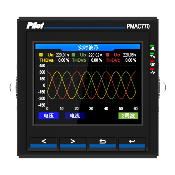
LAN) ·Modbus: master device adjust the system time over writing Modbus register list number. 4.15 Store function PMAC770H provides 128MB storage capacity for storing data including waveform record, SOE record, PQ events etc. 4.16 Real-time waveform PMAC770H provides a real-time waveform display function, waveform including... -
Page 44: Chapter 5. Display And Settings
Chapter 5. Display and settings PMAC770H equips with a TFT colorful LCD which with resolution of 320×240. 5.1 Button PMAC770H equips with 4 buttons on front panel, functions of each button are show as below: Button Description Move cursor to left, or turn page to left “... -
Page 45: Basic Measurement
5.3.1 Basic measurement The basic parameter measurement page is consists of 11 sub menus, which including phase voltage, line voltage, Zero ground voltage , phase current, active power, neutral current , active power , reactive power,apparent power , power factor , frequency, current demand, power demand, digital input, relay etc. -
Page 46: Power Quality
energy etc.: 5.3.3 Power quality Power quality page is consists of 7 sub menus, which including phase diagram, imbalance rate, sequence components, deviation, crest factor, flicker and current etc. 5.3.4 Event record Event record page display the events including phase voltage over limit, phase voltage under limit etc. -
Page 47: Real-Time Waveform
Item Description Previous page Turn to previous page Next page Turn to next page Turn to“1/1”page Turn to specified page, 1/1: 1: current page 1: total page(s) 5.3.5 Real-time waveform Real-time waveform page including three-phase current and three-phase voltage waveform. -
Page 48: Waveform Recording
Item Description Switching button Voltage Voltage secondly value(220V/480V system) “<” / “>” Current Current secondly value 2 points/cycles 1point/ cycles, 2 points/cycles(default), 4 points/cycles “ ” 5.3.6 Waveform recording Waveform recording function records three phase voltage swell, sag and interruption events. - Page 49 5.3.7.1 Communication setting Communication setting page shows parameters including Ethernet and 2 RS485 interface info:...
- Page 50 Set register list Factory default Description RS485#1 setting 1 ~ 247, each device shall have a unique ID for Device ID devices connected in a same circuit Baud rate 9600 1200/2400/4800/9600/19200/38400bps Data bit 7 or 8 Parity bit None None, Odd, Even Stop bit 1 or 2 RS485#2 setting...
- Page 51 5.3.7.2.1 Wiring mode setting Wiring mode setting page is used to modify wiring mode, PT ratio, CT ratio etc. Parameters table: Item Factory Default Range Wiring mode 3P4W 3P4W,3P3W PT ratio 1.00 1.00-6900.00 CT ratio 1.00 1.00-10000.00 5.3.7.3.2.2 Pulse setting...
- Page 52 Pulse setting page is mainly used to set pulse constant. Item Factory default Range 3600 0-65536 Pulse constant(imp) 5.7.3.2.3 Demand parameter setting Demand parameter setting page is used to set demand mode, demand cycle and slip width: Item Factory default Range Demand mode Fixed mode...
- Page 53 AO parameter setting table: Item Factory default Range Null/Ua/Ub/Uc/Uab/Ubc/Uca/Ia/Ib/Ic/ Object Null /frequency Max range(secondly value) 0.00 U/I/frequency:0.00~9999.99 :-9999.99~9999.99 Min range(secondly value) 0.00 PF:-1.000~+1.000 Coefficient of ranger 1~10000 5.3.7.2.5 Relay setting Relay setting page is used to setup the relay working mode, when local control is selected, then relay output is represent alarm output, when remote control is selected, then relay shall respond to the master device to perform open/close command.
- Page 54 Setting table: Item Factory default Range 1~6 relay Local Local mode or remote mode 5.3.7.2.6 Load setting Load setting page including upper limit setting for voltage, current and total active power, and lower limit for voltage only. Setting table: Item Factory default Range Object...
- Page 55 5.3.7.3.1 Voltage swell/sag/interruption This page can be used to set voltage swell, sag and interruption for each phase(Ua,Ub,Uc): The parameter settings including threshold and hysteresis value:...
- Page 56 etting table: Item Factory default Range Threshold 220.00V 0-999.99V Hysteresis 0-999 5.3.7.3.2 Other This page is mainly used to set CO2 emission factor. Setting table: Item Factory default Range CO2 emission factor 0.785 0 - 65.536 5.3.7.4 Alarm setting Alarm setting page consist of 7 sub menus, they are voltage setting, current setting, frequency setting, power setting, imbalance setting, harmonic distortion setting and other settings.
- Page 57 5.3.7.4.1 Voltage setting Voltage setting page including 11 sub setting menus for phase voltage over limit, phase voltage lower limit, average phase voltage over limit, average phase voltage over limit, line voltage over limit, line voltage lower limit, average line voltage over limit, average line voltage lower limit, neutral line to ground voltage over limit, neutral line to ground voltage lower limit, voltage loss etc.
- Page 58 Setting table: Item Factory default Range Enable On or off Relative None None/R1/R2/R3/R4/R5/R6 Threshold(V,kV) 1.00 0.00 - 999.99(kV) Hold time(S) 0 - 999 0.00-655.35 Hysteresis(V) 5.3.7.4.2 Current setting Current setting page including 6 sub setting menus for current over limit, current lower limit, neutral line current over limit, neutral line current lower limit, average current over limit, average current lower limit.
- Page 59 Setting table: Item Factory default Range Enable On or off Relative None None/R1/R2/R3/R4/R5/R6(R stands for relay) Threshold(A,kA) 1.00 0.00 - 999.99(kA) 0 - 999 Hold time(S) 0.00-65.53 Hysteresis(A) 5.3.7.4.3 Frequency setting Frequency setting page including upper and lower limit setting for frequency parameter.
- Page 60 Setting table: Item Factory default Range Enable On or off Relative None None/R1/R2/R3/R4/R5/R6(R stands for relay) 1.00 0.00 - 999.99 Threshold(pf) Hold time(S) 0 - 999 0.00-655.35 Hysteresis(%) 5.3.7.4.4 Power setting Power setting page is consists of 17 sub menus, which including active power upper limit, active power lower limit, total active power upper limit, total active power lower limit, reactive power upper limit, reactive power lower limit, reactive power lower limit, total reactive power upper limit, total reactive power lower limit, apparent power upper limit,...
- Page 61 Active power setting table(reactive power setting same as this part): Item Factory default Range Enable On or off Relative None None/R1/R2/R3/R4/R5/R6(R stands for relay) Threshold(W,kW,MW 1100.00 -20MW - 20MW 0 - 999 Hold time(S) Hysteresis (W) 0 - 655.35 Apparent power setting table: Item Factory default Range...
- Page 62 5.3.7.4.5 Imbalance rate setting Imbalance rate setting page is consists of 4 sub menus, which including negative sequence voltage imbalance rate upper limit, negative sequence current imbalance rate upper limit, zero sequence voltage imbalance rate upper limit, zero sequence current imbalance rate upper limit.
- Page 63 5.3.7.4.6 Harmonic distortion setting Harmonic distortion setting page is consists of 14 sub menus, which including voltage THD upper limit, current THD upper limit, voltage 3 harmonic upper limit, voltage 5 harmonic upper limit, voltage 7 harmonic upper limit, voltage 9 harmonic upper limit, voltage 11 harmonic upper limit, voltage 13...
- Page 64 Setting table: Item Factory default Range Enable On or off Relative None None/R1/R2/R3/R4/R5/R6(R stands for relay) Threshold (%) 0 0 - 100.00 Hold time(S) 0 0 - 999 Hysteresis 0 - 100.00 (%) 5.3.7.4.7 Other settings Other settings page is consists of 15 sub menus, which including DI1 open, DI2 open, DI3 open, DI4 open, DI5 open, DI6 open, DI7 open, DI8 open, DI9 open, DI10 open, DI11 open, phase voltage deviation upper limit, line voltage deviation upper limit, frequency deviation upper limit, phase voltage deviation rate etc.
- Page 65 DI parameter setting page: Setting table: Item Factory default Range Enable On or off Relative None None/R1/R2/R3/R4/R5/R6(R stands for relay) Threshold open Open or close 5.3.7.5 System settings System settings page including 3 sub setting menus, they are working mode setting, 系统...
- Page 66 5.3.7.5.1 Working mode setting Setting table: Item Factory default Range Mode Measurement mode Measurement mode, commissioning mode 5.3.7.5.2 Time setting Setting table: Item Factory default Range Date Current date(factory calibrated) 2022-01-01 - 2099-01-01 Time Current time(factory calibrated) 00:00:00-23:59:59 5.3.7.5.3 Language setting Setting table: Item Factory default...
- Page 67 5.3.7.6.1 User parameter User parameter clear page is show as below, a password is needed to proceed the operation, the default password is 888. 5.3.7.6.2 Demand extreme value Demand extreme value clear page is show as below, a password is needed to proceed the operation, the default password is 888.
-
Page 68: System Info
5.3.7.7 System reboot A password is needed for proceeding system reboot operation, the default password is 888. 5.3.8 System info... - Page 69 Item Contents Device state Product name, model, software version, add, manufacturer info System state Operation system, CPU, running time, RAM,ROM, system temperature...
-
Page 70: Chapter 6. Technical Specification
Chapter 6. Technical specification 6.1 Device parameters PMAC770H meets standard of GB/T 17215.321-2021 for static meters for active energy class D requirement, and meets the standard of GB/T 19862-2016 for general requirements for monitoring equipment of power quality. Communic Measured parameters... - Page 71 Flicker Voltage Real-time RMS Primary Primary Phase/line/average 0.1% value value Phase/zero Primary Primary 0.1% sequence/average value value Primary Primary Single/three phase 0.2% value value Single/three phase Primary Primary 0.5% value value Single/three phase Primary Primary 0.2% value value Single/three phase Primary Primary 0.2%...
-
Page 72: Performance Specification
Primary Primary Frequency Frequency 0.01Hz value value Communication 2 RS485 ports, 1 10/100M Ethernet port Relay output 4 normal open relays Digital input 8 active digital inputs or 8 passive digital inputs Pulse output 2 settable pulse outputs for active energy and reactive energy( secondly full wave energy pulse) Clock Device local clock(0.5s/day) - Page 73 Impulse voltage 6kV(peak value),1.2/50μs Item Standard Test level Electrostatic discharge GB/T17626.2-2006 Class 4 immunity (IEC61000-4-2:2001) Radio frequency GB/T17626.3-2006 electromagnetic field radiation Class 3 (IEC61000-4-3:2002) immunity Electrical fast transient burst GB/T17626.4-2008 Class 4 immunity (IEC61000-4-4:2004) GB/T17626.5-2008 Surge immunity Class 4 (IEC61000-4-5:2005) Conducted disturbance GB/T17626.6-2008...
-
Page 74: Chapter 7. Maintenance And Troubleshooting
Chapter 7. Maintenance and troubleshooting Issue Cause Solution No display Check if terminal L/+ and N/- are connected Device power on after powering with a right rated power supply. Check if the failed fuse has been burned down Check if the neutral line connection is well Incorrect voltage Check if the measured voltage is matched to measurement... - Page 75 communicate Device baud rate is Check if the device baud rate is same as with the not correct defined meter Resistance did not Check if the 120Ω resistance has been connect to connected to the communication circuit communication end Interference with the Check if the communication shielded twisted communication circuit pair connection is well...
- Page 76 Notice: PILOT reserves the right to modify this manual without prior notice if there is anything needed to change. Marketing email: marketing@pmac.com.cn Technical support: systemtech@pmac.com.cn Add:No. 15, keji 6 road, Chuangxin Haian, Tangjia high-tech zone, Zhuhai, Guangdong, China Postal code:519080 Tel:400-878-6678 Fax:0756-36296003629670...
Need help?
Do you have a question about the PMAC770H and is the answer not in the manual?
Questions and answers