
Subscribe to Our Youtube Channel
Related Manuals for Pilot Communications PBAT-Gate


Summary of Contents for Pilot Communications PBAT-Gate
- Page 1 PBAT-Gate Battery Monitoring System Installation & Operation Manual V3.3 珠海横琴派诺技术有限公司 PILOT (HENGQIN) CO., LTD.
- Page 2 Danger and warning! This device can be installed only by professionals. The manufacturer shall not be held responsible for any accident caused by the failure to comply with the instructions in this manual. Risks of electric shocks, burning, or explosion ...
-
Page 3: Table Of Contents
Content Chapter 1 Introduction ..........................1 1.1 System Structure ........................3 1.2 Applications ..........................4 1.3 Measurement ..........................4 Chapter 2 Installation and Wiring ......................5 2.1 Environment ..........................5 2.2. Installation and Usage ......................5 2.3 Order Information........................11 2.4 Power Supply ......................... - Page 4 4.10 Setting ............................ 25 Chapter 5 SNMP Agent ........................38 5.1 Summary ..........................38 5.2 OID Define ..........................38 5.3 Data Query ..........................39 Chapter 6 Data collection ........................40 6.1 Summary ..........................40 6.2 Collector function ........................40 Chapter 7 Data Forwarding Function ....................42 7.1 Summary ..........................
-
Page 5: Chapter 1 Introduction
Chapter 1 Introduction The battery monitoring system is used for the performance testing of various battery strings, comprehensive measurement to determine battery performance, and the failure of the battery will display and alarm, the battery can also be effectively activated maintenance, Can be real-time monitoring of the battery running status and its operating parameters, the battery pack self-diagnose and automatically make the appropriate maintenance, you can use the network to achieve remote, telemetry, control intelligent monitoring system. - Page 6 ( 6 ) Distributed deployment and Ethernet network management, can adapt to any environment seamlessly site (7)Detailed historical data recording, sound alarm event management, provide battery maintenance, failure analysis, report generation from data support (8)A variety of alarm linkage, So quickly found unexpected events...
-
Page 7: System Structure
1.1 System Structure PBAT battery monitoring system consists of a gateway module, single acquisition module, battery pack collection module, Hall sensors, temperature and humidity sensors and datacenters, each module functions as following: Module Name Illustration Realization battery data acquisition, control, alarm and Gateway event logging upload Single acquisition... -
Page 8: Applications
1.2 Applications PBAT battery monitoring system: (1) Support to monitor single unit 2V or 12V battery (2) Support to monitor single group 1-120 units cell snesors. (3) Measurement Maxim group voltage 20-800V (4) Measurement current -1000A---+1000A (5)Flexible installation, scalability for high reliability requirements such as finance, railways, telecommunications, electricity, mining and other occasions;... -
Page 9: Chapter 2 Installation And Wiring
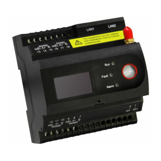
Chapter 2 Installation and Wiring 2.1 Environment (1)Standard operating temperature:-10℃~ +55℃ (2)Operating temperature limit:-25℃ ~ +55℃ (3)Storage temperature:-40℃~ +70℃ (4)Working humidity:5% ~ 95%RH,Non-condensing 2.2. Installation and Usage PBAT battery monitoring system is divided into a gateway module, Cell Sensor module, String Sensor module. Gateway module 2.2.1 Use rail installation, fixed on the rail. - Page 10 (2)Installation (3)The main terminal definitions(Gate L4 4CG): Symbol Definition 24V+ 24V DC power supply positive terminal input 24V- 24V DC power supply negative terminal input Null Null Null Null Null Null Null Null RS485A B- RS485A- RS485A A+ RS485A+ RS485A SHEL RS485A Shield RS485B B- RS485B-...
- Page 11 RS485B A+ RS485B+ RS485B SHEL RS485B Shield RS485D SHEL RS485D Shield RS485D A+ RS485D+ RS485D B- RS485D- RS485C SHEL RS485C Shield RS485C A+ RS485C+ RS485C B- RS485C- LAN1 Port 1 (10M/100M) LAN2 Port 2 (10M/100M) TF(Cover) TF Card(Standard) The main terminal definitions(Gate L4 2ZG): Symbol Definition...
- Page 12 RS485B SHEL RS485B communication line shield 4-20mA I1 input + 4-20mA I1(2) input + 4-20mA I2 input + Switch input 1 Switch input 2 Switch input 3 Switch input 4 Scom Common port of switch port LAN1 Ethernet 1 (10M/100M) LAN2 Ethernet 2 (10M/100M) Cell Sensor module...
- Page 13 (2) Installation Disassemble Installation Stickers (3) The main terminal definitions: Symbol Definition V- Bat DC Power supply input - V- Sense Negative voltage terminal Temperature terminal Temperature terminal V+ Sense Positive voltage terminal V+ Bat DC Power supply input + COM 1 Series 1 COM 2...
- Page 14 String Sensor module 2.2.3 (1) Dimension (2) Installation (3)Definition of main terminal Symbol Definition 24V DC power supply positive terminal input +24V 24V DC power supply negative terminal input -24V Hall Terminal Group Current Hall Sensor connect Group voltage measure - Group voltage measure +...
-
Page 15: Order Information
RS485+ RS485+ RS485- RS485- BM-BUS communication,RJ11 port COM1 BM-BUS communication,RJ11 port COM2 (4)Definition of indicator Symbol Definition RUN L1(GREEN) Device running normally ALARM2(RED) Alarming 2.3 Order Information The complete model specifications and the meaning of each code are shown in the following table: Model:... -
Page 16: Power Supply
2.4 Power Supply Module Power Supply Note Gate 18V-36V DC 5W 24VDC power supply 12V-36V DC 24VDC power supply 61-02 2V DC 2V battery unit power supply 61-12 12V DC 12V battery unit power supply... -
Page 17: Chapter 3Display And Operation Instruction
Chapter 3Display and Operation instruction 3.1 Summary within 30s, the display will OFF automatically, until the key operation will be displayed again. 3.2 Key features Gate panel has only one button to control the screen switch, you can press the button to achieve the screen cycle display. - Page 18 3.3.1 Time Display Interface Data Display: Displays the current battery gateway time 3.3.2 Network port configuration Display interface P address, gateway address, subnet mask The network port 2 is displayed in the same way as the network port 1. 3.3.3 Default gateway interface Data Display: Default gateway IP...
- Page 19 3.3.4 Gateway Information Display Interface Data Display : Gateway serial number 3.3.5 Gateway software Version Interface Data Display: Software version number 3.3.6 SIM Status Info Data Display: SIM Status SIM signal 3.3.7 Serial port display interface Data Display: Sequentially displaying the number of the baud rate, number of data bits, parity, and data bit settings.
-
Page 20: Chapter 4 Webpage Illustration
Chapter 4 Webpage Illustration 4.1 Summary Gate provides web configuration and data viewing for battery management and debugging. Web page can do basic operation parameter configuration, the battery current and historical data, log files from the gateway, engineering view, system firmware upgrade. 4.2 Login Connect the gateway to a PC(if there is LAN wireless router, you can use your tablet or smart phone to log in), open the IE browser(supportsIE9 +,Firefox, chrome and other... -
Page 21: Real-Time Data
4.3 Real-time Data After a normal login, click on the left menu bar [Real-time Data] to show the battery management information page: Real-time data page manage battery voltage, current, temperature, internal resistance, and battery collector connection status. Click the switch TAB to switch group information, cell information and digital input information, as shown in the figure below. -
Page 22: History Data
Group info: Cell info: Digital input info: 4.4 History data Click the left menu bar“Historical data”, display the battery history data page:... - Page 23 Note: PBAT-Gate can Max. storage history alarm record for 2 years. For those record that longer than 5 years, the Gate will delete the oldest 1 months data. Historical data will work after the Gate insert TF Card, in accordance with the maximum...
-
Page 24: Discharge Data
3cellsis hidden, click on the line can be displayed. Note: PBAT-Gate can Max. storage history alarm record for 2 years. For those record that longer than 2 years, the Gate will delete the oldest 1 months data. -
Page 25: Reports
load capacity calculation (240 monomer collector) of voltage, current, temperature, the internal resistance of the measuring point were recorded. Recommended TF card capacity is greater than or equal to 8G 4.6 Reports Click the menu in the left side “Reports”, display report page, including string battery data reports and cell battery reports. -
Page 26: Fault Statistics
4.7 Fault Statistics Click the menu in the left side “Fault statistics”, display fault statistics page When select “year”, it can display each months alarm statistics quantity. When select “month”, it can display each day of the month’s alarm statistics quantity. When select “month”, can select 12 months of the year. - Page 27 The second page shows the recent 200 untreated alarm information. When the gateway is restarted or reconfigured, the real-time alarm display will be reset.
-
Page 28: Alarm History
4.9 Alarm History Click the menu in the left side “Alarm History”, display historical alarm records. When the first checkbox string is selected, multiple cells or all cells can be selected; When the second checkbox string is selected, the alarm of the choosing string is queried. The end time must be greater than or equal to the start time, with maximum support for the cross one year query data. -
Page 29: Setting
SMS records page record the last 100 SMS messages with contacts, content, time of delivery, whether to send a successful message. 4.10 Setting Click the menu in the left side “setting”, then it will display submenu 4.10.1 Network Setting Click the menu in the left side “Setting”” ””Network Setting”, then it General Setting will display network parameter setting page. - Page 30 Display configuration 4-channel serial port configuration, including baud rate, data bits, stop bits, parity bit. 4 channels Default parameters: baud rate: 9600, data bits: 8, stop bit: 1, parity: none. This setting changes the Gate's own serial parameter configuration, not to change the PBAT600 serial port parameters, to change the 600 serial parameters, please contact the professional staff.
- Page 31 You can modify the minimum and maximum values of the AI input. Generally it is not recommended to modify it yourself. 4.10.4 Alarm setting Click the left menu bar “Setting” ->“General Setting” ->“Serial Port Setting” to display the Alarm setting page. This function convenient...
- Page 32 Alarm editing interface: Alarm function ON or OFF Upper limit value Recovery value Normally is 0 Normally is 0 Select DO alarm or SMS Change the trigger action can choose SMS alarm Set the SMS contents, alarm message and recover message you want to send. SMS alarm content SMS alarm content SMS alarm content...
- Page 33 the confirmation and then click to confirm. Pop-up page display: 4.10.5 Resistance Measurement Click the left menu bar “Setting” ->“General Setting” ->“Resistance Measurement” to display the resistance measurement page. Click the pop-up prompt "Are you sure you want to test the internal resistance manually?" Testing the internal resistance need to wait for a long time, each monomer takes about 5...
- Page 34 seconds. Note:Automatic measurement of internal resistance controlled by, the default is 24 hours test once. 4.10.6 Time setting Click the left menu bar “Setting” ->“General Setting” ->“Time setting”to display the time setting page. Select the time zone, the default Beijing time zone (East 8 District). The calibration time server can be the domain name or IP address of the NTP server:...
- Page 35 4.10.7 User Manager Click the left menu bar “Setting” ->“General Setting” ->“User Manager” to display the user manager page You can add a user, the user parameters including user names, passwords, user identity, surname, name and contact information. You can delete all users(except the SuperAdmin), and you will be prompted before deleting them.
- Page 36 Set the balance when the balance is lower than the set value (if 90% means that the balance is turned on when the balance is lower than 90%) Set the interval time, the minimum interval for each balancing function execution, to prevent damage to the battery Res Balance(%):Used for internal resistance balance judgment, used for data upload.
- Page 37 Mainly displays the information at the head and bottom of the page. Modifying a language can change the default language when you log in and import warning template , and affect the language used when sending text messages. The timing record setting set the interval time of record historical data. Logo settings for the login screen Logo display and the upper left corner of the user's Logo display 4.10.11 Battery Information...
- Page 39 Displays the added battery string data. Including the manufacturer, model, capacity, voltage type, internal resistance reference value, generation time, commissioning time, cut-off voltage, recovery voltage, float current limit, float current limit. Note: The battery voltage display selects the measured value: the actual measured group voltage value;...
- Page 40 Hall sensor from the line, placed under no current conditions. PBAT600 version info:When the communication is successful, the PBAT600 version information is displayed 4.10.12 Address Map Click the left menu bar “Setting” -> “Service Configuration” -> “Address Map” to display the address map page.
- Page 41 4.10.13 Forward Table Click the left menu bar “Setting” -> “Service Configuration” -> “Register List” to display the ModbusTCP Forward Table page. Can be loaded, empty, and export the collector table. V3.1 support alarm information forwarding, refer to Gateway protocol V3.1. Note: Before uploading the gateway data, please click "Import List"...
-
Page 42: Chapter 5 Snmp Agent
Chapter 5 SNMP Agent 5.1 Summary SNMP is a network management standard based on TCP/IP protocol and is a standard protocol for managing network nodes (such as servers, workstations, routers, switches, etc.) in IP networks.SNMP can enable network administrators to improve network management efficiency, timely discover and solve network problems and plan network growth.The network administrator can also receive the notification message of network node and the alarm event report through SNMP to... -
Page 43: Data Query
address 1.3.2.3.1.2.4. 8072.1.3.2.3.1.2.4.51, group of four children starting address 1.3.2.3.1.2.4. 8072.1.3.2.3.1.2.4.52 5.3 Data Query Using snmpwalk command can traverse the nodes under all child nodes, such as a child node to traverse the group under all the data, can use snmpwalk -v 2c -c public 192.168.1.XX .1.3.2.3.1.2.4.8072.1.3.2.3.1.2.4.49 Using the snmpget command, you can obtain data for the specified node, for example, to obtain the data of the single voltage 1 under the group node, can use... -
Page 44: Chapter 6 Data Collection
Chapter 6 Data collection 6.1 Summary PBAT-GATE gateway provide 4 channel RS485 communication, collect battery data at setting time, equipped with Control linkage alarm, inner resistance testin 6.2 Collector function Collector module including single cell unit collector and battery group collector. Each... - Page 45 Can choose following Combinations: Group Number Channel Note 4CG: RS485-A: 1-120(61) The gateway connect with 4 group Group 1, Group 2 、 (Group 1) 1-240(62) battery. Number of each group cannot be more than 120. Number Group 3, Group 4: RS485-B: 1-120(61) Group...
-
Page 46: Chapter 7 Data Forwarding Function
Chapter 7 Data Forwarding Function 7.1 Summary PBAT-GATE support both web view function and data forward function. This gateway support multi-Host TCP connection, In theory there is no limit on the number of connections, but the actual use is recommended to limit the number of connections no more than 20 7.2 Forwarding table configuration... - Page 47 starting address is 0 and reading register number is 10 3.Setthe read register starting address and display format【display】->【float inverse】 4.After configuration, can sequentially to read the battery real-time data, one message can read maxim 512 measuring point. When a larger number of measuring points need to get real-time data, can divide into several sections 5.If there are several data center need to read the data from gateway at the same time, can connect all of them to port 502 on the gateway.
-
Page 48: Chapter 8 Alarm System
Chapter 8 Alarm System 8.1 Summary PBAT with customer customized alarm system, can monitor battery monitoring system all parameters and set the linkage, set the alarm parameter (no quantity limit), support all the measuring point over limit alarm. 8.2 Alarm Analysis 8.2.1 Alarm Judge Type There are two types: Upper Limit and Lower Limit, the value can be customized 8.2.2 Alarm Object Type... - Page 49 Single Cell unit voltage Single Cell unit temperature Single Cell unit inner resistance Timing records Battery group voltage Battery group current Alarm Action Condition 8.2.3 After define monitoring parameters, need to set the action condition For example: define single cell unit voltage upper limit action Set the battery group number, event type set as upper limit, limit value 2.5V, trigger action is [Event Record].
- Page 50 Alarm Holding Time 8.2.4 When the alarm object fulfill over limit condition, still need fulfill the time requirement can be absolutely activated. In the total delay time, if the alarm object return back to the limit value, then will not be activated. The unit for activation delay is second, value range is 0-65535. If set the value to 0, it means the alarm will be activated at the moment object over limit Alarm Hysteresis value...
- Page 51 Trigger activation including: action to remind the maintenance staff, Trigger Activation Illustration Alarm---ON Cancel---OFF LED Light (Alarm light including gateway panel light and collector light) Event Record record alarm and cancel Can be connected to sound and light DO (2ZG version) alarm for alarm Attention:If use the 2ZG version, only support 2*RS485.
-
Page 52: Chapter 9 Auxiliary Function
Chapter 9 Auxiliary Function 9.1 Communication PBAT-GATE with maxim 4 RS485 port, 4 of them independent from each other. PBAT600, PBAT61-02, PBAT61-12 Please refer to following wiring example, in the actual application, In order to prevent signal reflection, normally need to add on parallel an approximately120-ohm resistor by the end of network PBAT-GATE with 2 port RJ45, support IEEE-802.3 Ethernet standard10BaseT/100BaseTX... -
Page 53: Chapter 10 Soc Remaining Capacity
details, see chapter 5.5.2 Chapter 10 SOC remaining capacity 10.1 SOC Remaining capacity calculating Description Gate supports the SOC calculation of a single cell, calculated once per minute. The SOC value within one minute of the first start is invalid and the SOC value in the first minute after the parameter is reconfigured is invalid. - Page 54 12V, or 12V change to 2V),The battery's characteristic parameters will be restored to the voltage level of the default feature parameters, the original parameters will be lost,be sure to understand this risk when switching battery voltage levels. The default [recovery voltage] value for a large number of experimental access to the optimal value, if no special circumstances(Such as battery manufacturers to provide reference value, etc.)...
-
Page 55: Chapter 11 Maintenance And Trouble Shooting
Chapter 11 Maintenance and Trouble shooting Problems Causes Solutions 1.Check 24V+ & 24V- terminal and make No display after sure with correct power supply Power supply failure power on 2.Check the fuse of power supply whether be burned 1.Check the connection voltage measurement Measuring value 2.Check whether measurement voltage... -
Page 56: Chapter 12 Technical Specification
Chapter 12 Technical Specification Panel: 96mm(L)× 96mm(W)× 13.5mm(H) Dimension Panel: Back & Side: Power Power selection:12~36VDC Supply Item Reference Standard Class GB/T17626.12-1998 Sasser immunity (IEC61000-4-12:1995) Electrostatic discharge GB/T17626.2-2006 immunity (IEC61000-4-2:2001) GB/T17626.3-2006 RFEMS (IEC61000-4-3:1998) Electrical fast transient GB/T17626.4-2008 burst immunity (IEC61000-4-4:1998) GB/T17626.5-2008 Surge Immunity (IEC61000-4-5:2005) - Page 57 Notice: PILOT reserves the right to modify this manual without prior notice in view of continued improvement. Marking Email: marking@pmac.com.cn Tech Support Email: systemtech@pmac.com.cn PILOT (HENGQIN) CO., LTD Add: No. 15, Keji 6 Road, ChuangxinHaian, Tangjia High-tech Zone, Zhuhai, Guangdong, 519085 China Tel:+86-756-3629166/3639029 Fax: +86-756-3631718...
Need help?
Do you have a question about the PBAT-Gate and is the answer not in the manual?
Questions and answers
SNMP MAP POINT to DCIM SYSTEM
To integrate the Pilot Communications PBAT-Gate with a DCIM system using SNMP MAP POINT, follow these steps:
` with the correct object identifier for the desired data.
1. Enable SNMP on PBAT-Gate – Ensure that SNMP is activated on the PBAT-Gate device.
2. Obtain SNMP OIDs – Use the `snmpget` command to retrieve data from specific nodes. For example, to get single voltage data, use:
```
snmpget -v 2c -c public 192.168.1.XX
```
Replace `
3. Configure DCIM System – In the DCIM system, add the PBAT-Gate as an SNMP device and enter the correct IP address and SNMP community string (e.g., "public" for read-only access).
4. Map SNMP Data Points – Use SNMP MAP POINT to associate specific OIDs with relevant parameters in the DCIM system, such as battery voltage, temperature, and current.
5. Test and Validate – Execute SNMP queries from the DCIM system to verify data retrieval and ensure accurate mapping.
6. Monitor and Maintain – Continuously monitor the integration and update configurations as necessary to accommodate changes in the PBAT-Gate system.
This setup allows the DCIM system to collect and display real-time battery monitoring data from PBAT-Gate using SNMP.
This answer is automatically generated