Table of Contents
Advertisement
Advertisement
Table of Contents

Related Manuals for Pilot Communications EGO700


Summary of Contents for Pilot Communications EGO700
- Page 1 EGO700 Multi Function Power Meter For Installation & Operation Manual V1.0...
- Page 2 Safety Precautions: General Warnings: This equipment can only be installed by professionals The manufacturer will not be responsible for any failure caused by NOT following the instructions in this manual Danger Warnings of Electric Shock, Combustion or Explosion: ...
-
Page 3: Table Of Contents
Contents Chapter 1 Product Overview..................5 Chapter 2 Product Selection................... 6 Chapter 3 Dimension......................7 3.1 Main part dimensions......................7 3.2 CTC closed current transformer module dimensions............7 3.3 CTO current transformer dimensions.................. 8 3.4 Host installation dimensions....................8 3.5 Host with CTC module installation dimension drawing............. 8 Chapter 4 Display and key operation instructions............9 4.1 Real-time measurement data display structure..............9 4.2 All show figure........................10... - Page 4 9.5 Typical wiring diagram...................... 25 9.5.1 CTC mode (built-in CT) wiring diagram..................26 9.5.2 External CT wiring diagram......................27...
-
Page 5: Chapter 1 Product Overview
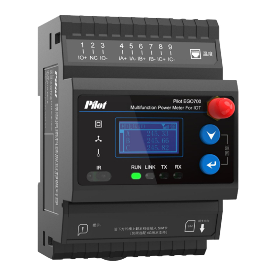
Chapter 1 Product Overview EGO700 Multi Function Power Meter For IOT is mainly applicable to the distribution cabinet and switch cabinet in the high and low-voltage distribution system lower than AC 650kV (phase voltage). It can communicate with RS485 / MODBUS bus to manage the meter network and realize automatic control. -
Page 6: Chapter 2 Product Selection
External 5A/1.67mA closed current transformer module ③:Extended function (optional) 4-way cable temperature Note: EGO700 is compatible with 3×57.7/100V and 3×220/380V rated voltage input. Example: EGO700-4G-CTO: Three-phase multi-functional power meter equipped with 1-way active switch quantity input, 4-way cable temperature, 1 channel residual current, 1-way 4G communication and 1-way RS485 communication external 5A open current transformer access. -
Page 7: Chapter 3 Dimension
Chapter 3 Dimension 3.1 Main part dimensions Unit:mm 72.50 63.00 66.00 Pilot EGO700 Multifunction Power Meter For IOT 3.2 CTC closed current transformer module dimensions Unit:mm 53.00 60.00... -
Page 8: Cto Current Transformer Dimensions
3.3 CTO current transformer dimensions Unit:mm 34.0±0.5 31.0±0.5 18.4±0.5 16.0 3.4 Host installation dimensions Unit:mm 3.5 Host with CTC module installation dimension drawing Unit:mm... -
Page 9: Chapter 4 Display And Key Operation Instructions
Chapter 4 Display and key operation instructions 4.1 Real-time measurement data display structure (1) Real-time measurement data shall be displayed in the form of main menu and sub-menu (2) Menu tree diagram ①P the main menu by the button... -
Page 10: All Show Figure
4.2 All show figure 1、Function title; 2、Unit display area; 3、4G signal display icon; 4、The 4G signal strength; 5、Main data display area; 6、Running indicator light: Flashing while running; 7、Network connection light: always on when connected to the Internet; 8、RS485/Lora sending indicator light: flashing when the device sends; 9、RS485/Lora receiving indicator light: flashing when the device receives;... -
Page 11: Setting Parameter Description
3. CT ratio: Press the key to enter the CT ratio Meter programming interface, as shown in the figure below. Set according EGO700 can be programmed with the following to field CT. CT ratio setting range: 1.00~100000.00 parameters: Programmable item... - Page 12 adjusted, and there will be a corresponding result popup prompt after the adjustment. 8.Power cleaning: Press the key to enter the setting interface of power cleaning, as shown in the figure below. Operation examples Switch between real-time data page and edit menu: ...
-
Page 13: Chapter 5 Measurement Performance
EGO700 must use CT to measure current. The secondary rated output of CT needs to meet the rated current input requirement of EGO700 (5A). When wiring the external CT, prevent the CT output from being open, otherwise a higher voltage will be generated in the secondary under the action of the primary excitation, causing personal injury or death or equipment damage. -
Page 14: Frequency
When EGO700 works in different measurement modes, the acquisition channels of frequency measurement are different. In the triangle mode, EGO700 measures frequency through the AB line voltage channel by default; in other modes, EGO700 measures frequency through the A phase voltage channel. If phase A lacks phase, phase B is selected. -
Page 15: Maximum Daily Demand
0. 5.5 Electric energy The active and reactive input and output power of EGO700 can accumulate up to 99999999.9kWh, and display one decimal place. When the accumulation reaches the highest value, it will automatically flip. -
Page 16: Unbalance
C current 5.9 Fixed value alarm The fixed value alarm parameters of the EGO700 device can be set by the host computer software through communication. When an alarm event occurs, the alarm type can be read through communication. There are 22 groups of monitored alarm objects, and each group of parameters includes the following: (1) Action mode: on/off. - Page 17 B-phase voltage lower limit, C-phase voltage lower limit, phase loss, A-phase current upper limit, B-phase current upper limit, C-phase Current upper limit, A phase current lower limit, B phase current lower limit, C phase current lower limit, total active power upper limit, frequency upper limit, frequency lower limit, residual current upper limit, first circuit temperature upper limit, second circuit temperature upper limit, third circuit temperature upper limit , The fourth circuit temperature upper limit, DI is disconnected.
-
Page 18: Phase Sequence Adjustment
A/B/C three-phase power factor is greater than 0.8; Chapter 6 Input-output characteristics 6.1 Switch value input EGO700 comes standard with 1-way active switch value input, which is suitable for monitoring status information of circuit breaker and switch. External active switch value. -
Page 19: Chapter 7 Technical Index
Chapter 7 Technical index Parameter Range Rated working power supply AC 85~265V or DC 100~300V Power consumption ≤ 2W/5VA Rated input current CTO:External 5A/1.67mA open current transformer CTC:External 5A/1.67mA closed current Rated working transformer module parameters Rate input voltage 3x220/380V 40Hz~65Hz Active switch input rated voltage 220V,If it is less than 60V, it is open;... - Page 20 Power frequency withstand 4000VAC(GB/T 17215.211) voltage Insulation Insulation resistance ≥ 100MΩ performance Surge voltage 6000V IP protection Front panel IP52 level Complete machine IP20 Iterm Reference standard Test class ElectroSTatic Discharge 4 level GB/T17626.2-2006 (IEC61000-4-2:2001) Radio frequency electromagnetic 4 level GB/T17626.3-2006 field radiation immunity (IEC61000-4-3:2002)
-
Page 21: Chapter 8 Maintenance & Troubleshooting
Chapter 8 Maintenance & Troubleshooting May issue Possible cause Possible solution device Check whether the correct operating voltage is applied to Power was not added to the display after adding the the L/+ and N/- terminals of the device.Check whether device control power the control power insurance is not burnt out... -
Page 22: Chapter 9 Appendix
Chapter 9 Appendix 9.1 Terminal diagram 9.2 Terminal definition table Terminals number Terminal definition Voltage terminal VA,VB,VC,VN Switching input terminal S1,SG Residual current terminal I0+,NC,I0- Current terminal IA+,IA-,IB+,IB-,IC+,IC- RJ45 Temperature of the terminal Communication terminal 485A+,NC,485B- Power terminal L,N... -
Page 23: Terminal Specification Table
9.3 Terminal specification table Definition Description Definition Description Definition Description A phase current A phase 485A+ 485 plus end input line voltage B phase current B phase 485B- 485 minus end input line voltage C phase current C phase Leakage current into the IO/+ input line voltage... -
Page 24: Residual Current Connection
(2) For LoRa communication, the antenna is located at the upper right part of the device. If the device is installed in the metal cabinet, the antenna shall be extended out of the cabinet to ensure the communication quality. (3) 4G communication. The lower right part of the device is 4G communication module. -
Page 25: Switch-Volume Connection
, and other states of the external contact. The corresponding status of DI is displayed on the panel. The wiring diagram of external active node is as follows: 9.5 Typical wiring diagram EGO700 supports a variety of measurement wiring modes, star and Angle wiring. - Page 26 9.5.1 CTC mode (built-in CT) wiring diagram Three-phase four-wire system: 图4:高压三相四线星型,3CT,3PT 图1:低压三相四线星型,3CT,无PT Low-voltage three-phase four-wire star, no PT, 3CT: High pressure three-phase four-wire star, 3PT, 3CT: VA VB VC VN IA+ IA- IB+ IB- IC+ IC- VA VB VC VN IA+ IA- IB+ IB- IC+ IC- Three-phase three wire system:...
- Page 27 9.5.2 External CT wiring diagram Three-phase four-wire system: 图1:低压三相四线星型,3CT,无PT 图4:高压三相四线星型,3CT,3PT Low-voltage three-phase four-wire star, no PT, 3CT: High pressure three-phase four-wire star, 3PT, 3CT: VA VB VC VN IA+ IA- IB+ IB- IC+ IC- VA VB VC VN IA+ IA- IB+ IB- IC+ IC- Three-phase three wire system: 图2:低压三相三线,3CT,无PT...
- Page 28 Typical wiring diagram of EGO700 Ⅰ: EGO700-CTO Low voltage three-phase four wire star wiring diagram EGO700 Power supply Current signal Voltage signal Typical EGO700 wiring diagram Ⅱ: EGO700-CTO High voltage three-phase three-wire (2PT2CT) angular wiring diagram AC 10KV EGO700 FU1/5A...
- Page 29 Typical wiring diagram of EGO700III: EGO700-CTC Low voltage three-phase four wire star wiring diagram EGO700 Power supply Current signal Voltage signal Typical EGO700 wiring diagram IV: EGO700-CTC High voltage three-phase three-wire (2PT2CT) angular wiring diagram AC 10KV EGO700 FU1/5A Power...
- Page 30 Notice: The information provided in this manual may be modified without prior notice. PILOT reserves the right to modify this manual without prior notice in view of continued improvement. Zhuhai Pilot Technology Co., Ltd. Add: No. 15, Keji 6 Road, Chuangxin Haian, Tangjia High-tech Zone, Zhuhai, Guangdong, 519085 China Tel:+86-756-3629687/3629688 Fax: +86-756-3629600/ 3629670...
Need help?
Do you have a question about the EGO700 and is the answer not in the manual?
Questions and answers