Table of Contents
Advertisement
Quick Links
Advertisement
Table of Contents

Related Manuals for THORLABS PDXC ORIC


Summary of Contents for THORLABS PDXC ORIC
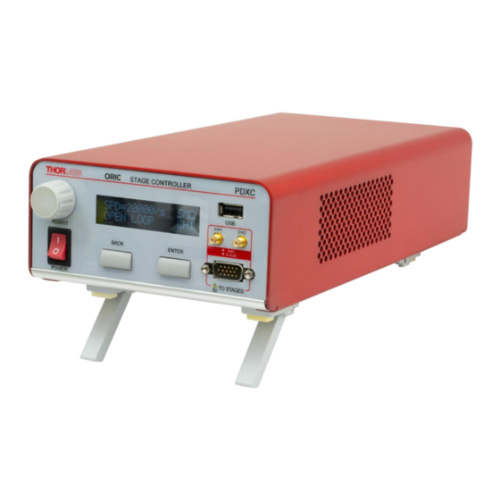
- Page 1 PDXC ORIC ® Piezo Stage Controller User Guide...
-
Page 2: Table Of Contents
® PDXC ORIC Piezo Stage Controller Table of Contents Warning Symbol Definitions ....................1 Chapter 1 Safety ............................ 2 Chapter 2 Overview ..........................3 Chapter 3 3.1. Introduction ........................3 Operation Principle ......................3 3.3 Stages Connection and Accessories ................4 3.3.1 Operation Elements ........................ - Page 3 6.3.27.DIS=n; DIS? – DEVICE DISABLE ..................47 Chapter 7 Maintenance ........................48 7.1. Fuse Replacement ......................48 Mechanical Drawing ......................49 Chapter 8 Chapter 9 Specifications ........................50 Chapter 10 Regulatory ...........................51 10.1. Declarations Of Conformity ..................51 10.2. CE Certificate ......................... 52 Thorlabs Worldwide Contacts ..................54 Chapter 11...
-
Page 4: Chapter 1 Warning Symbol Definitions
® ORIC Piezo Stage Controller PDXC Chapter 1: Warning Symbol Definitions Warning Symbol Definitions Chapter 1 Below is a list of warning symbols you may encounter in this manual or on your device. Symbol Description Direct Current Alternating Current Both Direct and Alternating Current Earth Ground Terminal Protective Conductor Terminal Frame or Chassis Terminal... -
Page 5: Chapter 2 Safety
® ORIC Piezo Stage Controller PDXC Chapter 2: Safety Safety Chapter 2 All statements regarding safety of operation and technical data in this instruction manual will only apply when the unit is operated correctly. SHOCK WARNING High voltage inside. To avoid electrical shock, before powering up, make sure that the ground pin of the power cord is correctly connected to the ground connector in the power socket. -
Page 6: Chapter 3 Overview
® ORIC Piezo Stage Controller PDXC Chapter 3: Overview Overview Chapter 3 3.1. Introduction The PDXC Piezo Stage Controller is designed to control our PD1(/M) Piezo Inertia Linear Translation Stage, PDX1(/M) Piezo Inertia Linear Translation Stage with an Optical Encoder, and PDR1(/M) Piezo Inertia Rotation Stage. -
Page 7: Stages Connection And Accessories
® ORIC Piezo Stage Controller PDXC Chapter 3: Overview backward. The slider does not move due to its inertia and the low coefficient of kinetic friction between the friction element and the bottom surface of the slider. Figure 3.2.1 shows the piezo drive voltage during one "stick-slip" cycle. - Page 8 ® ORIC Piezo Stage Controller PDXC Chapter 3: Overview Two SMC ports for connecting to two PD1(/M) open-loop stages. One DB15 port for connecting to one PDX1(/M) stage. Figure 3.3.1 Connections Between Stages and Controller #1 The section below lists the connection components and accessories packed along with this controller. The PDXC controller is compatible with 100 - 240 VAC, 50 - 60 Hz power sources.
-
Page 9: Operation Elements
® ORIC Piezo Stage Controller PDXC Chapter 3: Overview Figure 3.3.2 Ethernet Cable Figure 3.3.3 I/O Cable Figure 3.3.4 USB Cable Figure 3.3.5 Power Supply Cable 3.3.1 Operation Elements 3.3.2 Front Panel USB (TYPE A) & D-SUB (15) Figure 3.3.6 PDXC Front Panel Connectors USB (Type A): Connects a general HID mouse (such as the Dell MS116C) to control the stage movement by scrolling... -
Page 10: Back Panel
® ORIC Piezo Stage Controller PDXC Chapter 3: Overview signal definition. Figure 3.3.7 15-Pin D-SUB Port Pin Assignment Pin No. Voltage Range Name Description -7.5 to +12.5 V Encoder_B_N Encoder B- -7.5 to +12.5 V Encoder_B_P Encoder B+ Digital Ground -7.5 to +12.5 V Encoder_A_N Encoder A-... - Page 11 ® ORIC Piezo Stage Controller PDXC Chapter 3: Overview Figure 3.3.10 I/O Port Pin Assignment Pin No. Voltage Range Name Description -10 to +10 V Analog In Input as New Target Position Ground Pin 0 to 5 V Trigger In Trigger to Update New Target Position Ground Pin Reserved...
- Page 12 ® ORIC Piezo Stage Controller PDXC Chapter 3: Overview Pin No. Voltage Name Description Range 5 V TTL Ext_Sync_p Daisy-Chain Clock 5 V TTL Ext_Sync_n Daisy-Chain Clock N.C. Not Connected Ground Pins N.C. Not Connected -10 to +10 V RS_485_p Positive Daisy-Chain Signal -10 to +10 V RS_485_n...
-
Page 13: Chapter 4 Panel Operation
® ORIC Piezo Stage Controller PDXC Chapter 4: Panel Operation Panel Operation Chapter 4 The PDXC Piezo Stage Controller can be operated in one of three ways: From the front panel Using the included software Using the command set This chapter will focus on the panel operation of PDXC Piezo Stage Controller. 4.1. -
Page 14: Move Stage In Closed-Loop Operation
® ORIC Piezo Stage Controller PDXC Chapter 4: Panel Operation Figure 4.2 D-Sub Mode Main Screen 4.2.1. Move Stage in Closed-Loop Operation In closed-loop mode, only the feedback signal from the encoder is monitored. The stages are driven by a default waveform according to preset velocity or step size. -
Page 15: Move Stage In Open-Loop Operation
® ORIC Piezo Stage Controller PDXC Chapter 4: Panel Operation the menu and follow the flow chart below. D-Sub mode main screen Press “ENTER” to enter the menu screen and select “CLOSED LOOP” Turn knob to select “VELOCITY” and press “ENTER” Turn knob to change the velocity value and press “ENTER”... -
Page 16: Set Step Size In Open-Loop Operation
® ORIC Piezo Stage Controller PDXC Chapter 4: Panel Operation D-Sub mode main screen Press “ENTER” to enter the menu screen and select “OPEN LOOP” Turn knob to select “VELOCITY” and press “ENTER” Turn knob to change the velocity value and press “ENTER”... -
Page 17: Save Parameters In D-Sub Mode
® ORIC Piezo Stage Controller PDXC Chapter 4: Panel Operation D-sub mode main screen Press “ENTER” to enter the menu screen and select “OPEN LOOP” Turn knob to select “STEP” and press “ENTER” Turn knob to change the step size and press “ENTER”... -
Page 18: Homing
® ORIC Piezo Stage Controller PDXC Chapter 4: Panel Operation D-Sub mode main screen Press “ENTER” to enter the menu screen and turn knob to toggle down the screen until it shows “SAVE” Press “ENTER” to save all operation parameters in D-SUB mode Press “ENTER”... -
Page 19: Encoder Calibration
® ORIC Piezo Stage Controller PDXC Chapter 4: Panel Operation D-Sub mode main screen Press “ENTER” to enter the menu screen and turn knob to toggle down the screen until it shows “HOME” Press “ENTER” to start homing Press “ENTER” again to confirm Figure 4.10 Start Homing Process 4.2.8. -
Page 20: Smc Output Mode
® ORIC Piezo Stage Controller PDXC Chapter 4: Panel Operation Figure 4.12 Step 1 of Calibration Step 2: The user moves the stage manually to its half range, starting from the middle position, toward either end of the travel range, back and forth, several times with very low speed (<10 mm/s). Figure 4.13 Step 2 of Calibration Step 3: The user moves the stage manually to its full range, from one end to the other, repeating this operation several times before going to Step 4. -
Page 21: Channel Selection
® ORIC Piezo Stage Controller PDXC Chapter 4: Panel Operation 4.3.1. Channel Selection To select the channel in SMC mode, press the “ENTER” button in main SMC mode screen to enter the menu. Then follow below flow chart select channel between Channel 1 (CH1) and Channel 2 (CH2). Select SMC mode after power on SMC mode main screen Press “ENTER”... -
Page 22: Set Step Size
® ORIC Piezo Stage Controller PDXC Chapter 4: Panel Operation SMC mode main screen Press “ENTER” to enter the menu screen and choose “PARAMETERS” Select “VELO” of the corresponding channel Turn knob to change the velocity value Figure 4.18 Set Velocity in SMC Output Mode 4.3.3. -
Page 23: Save Parameters
® ORIC Piezo Stage Controller PDXC Chapter 4: Panel Operation SMC mode main screen Press “ENTER” to enter the menu screen And choose “PARAMETERS” Select “STEP” of the corresponding channel Turn knob to change the step size Figure 4.19 Set Step Size in SMC Output Mode 4.3.4. -
Page 24: Over Current Protection
The PDXC allows users to update its firmware. The most up-to-date firmware and the firmware update tools are both available on the software tab of the PDXC page on the Thorlabs website (www.thorlabs.com). To update the controller firmware, connect the controller to a PC with the USB cable included. Keep holding down the BACK button when powering on the device, then the device will enter the bootloader program designated for firmware updates. - Page 25 Piezo Stage Controller PDXC Chapter 4: Panel Operation On the PC, start the firmware update tool, which can be download from the website (http://www.thorlabs.com/), select the correct COM port, and connect. Figure 4.23 Select COM port on Firmware Update Tool Click “Browse”...
-
Page 26: Chapter 5 Software
Software Chapter 5 Thorlabs provides a bundled software for the PDXC which accesses all the features supported by the controller. It comes with each PDXC unit and can also be downloaded from Thorlabs website. We also provide C/C++ and LabVIEW® software development kits for controlling the PDXC with other instruments through the USB port on the controller. - Page 27 Update Update the PDXC software to the most up-to-date version. Support Microsoft Outlook launches (if installed) and directly addresses to techsupport@thorlabs.com. About Displays the detailed information about the PDXC software. Help There are links to the PDXC manual, SDK for C++, Labview, Python, and License documentation.
-
Page 28: Device Status Buttons
® ORIC Piezo Stage Controller PDXC Chapter 5: Software 5.1.2. Device Status Buttons On the bottom right, there are three device status buttons: Enable: Enable the device. Changes to green color when enabled. Store: Store parameters to permanent memory. Home: Return the stage to home position, changed to green color when home is successful. -
Page 29: External Trigger Mode
® ORIC Piezo Stage Controller PDXC Chapter 5: Software In closed-loop mode, the encoder feedback signals of position and velocity are measured and compared to the set value. A PID control loop automatically corrects the driving signal applied to the stages according to the error between the measured position and velocity and the targe position and velocity. -
Page 30: Smc Output Mode
® ORIC Piezo Stage Controller PDXC Chapter 5: Software Figure 5.5 Fixed Step Size Operation in Trigger Mode Fixed Positions: In this sub-mode, the user can make use of the “Trigger In” pin of I/O port to move the stage between two positions (Pos1 and Pos2). -
Page 31: Daisy-Chain Operation
® ORIC Piezo Stage Controller PDXC Chapter 5: Software Figure 5.8 Options in SMC Mode Under the Options button, there are output amplitude settings shown as below: for both “Forward Amplitude” and “Backward Amplitude”, the range is from 10% to 100%. This feature allows users to adjust the forward and backward speed of the stages in SMC mode separately. -
Page 32: Physical Connection And Set-Up
® ORIC Piezo Stage Controller PDXC Chapter 5: Software 5.3.1. Physical Connection and Set-up When preparing for the daisy-chain connection, we need to connect all devices in serial (one device’s daisy-chain IN port connect to next device’s daisy-chain OUT port on rear panels) by using ethernet cables. Since there is only one Main in this chain, the to-be-Main device should be the start end of chain, as shown in Figure 5.8. - Page 33 ® ORIC Piezo Stage Controller PDXC Chapter 5: Software Figure 5.12 Set the First Device as Main Connect the second device from the daisy chain to PC via USB, and set it to secondary 1 in the option menu. Figure 5.13 Set up Secondary Device Repeat this process for all the secondary units that need to be connected.
- Page 34 ® ORIC Piezo Stage Controller PDXC Chapter 5: Software Figure 5.14 Select Main Device and Start Daisy Chain Select the Main device, and Click Daisy-Chain Connect on the buttom left corner. Then the below window will show. Figure 5.15 Select Secondary Devices to Run Select the secondaries to run;...
-
Page 35: Daisy-Chain Operations
® ORIC Piezo Stage Controller PDXC Chapter 5: Software Figure 5.16 Daisy-Chain Main Window In the diasy chain GUI, there will be multiple control panels, each corresponding to a controller. In this case, two panels will be shown. In this time, the display on the controller front panel changed: the Main has “M0” on it, while device Secondary 1 has “S1”... -
Page 36: Raster Scan Operation
® ORIC Piezo Stage Controller PDXC Chapter 5: Software Figure 5.19 Sync Function is Active Once the parameters are set for all devices, the user can click Jog and Move on the Main panel, so that all stages will move at the same time. It should be noticed that the Sync will become available only when all secondary devices are in the same loop mode with the Main (either all are in Open Loop or in Closed Loop), and will automatically become unavailable if the devices are not in the same loop. -
Page 37: Operation Of Scan
® ORIC Piezo Stage Controller PDXC Chapter 5: Software not forget the ground connection between the two devices. 5.4.2. Operation of Scan Insert both the USB cables of the devices to the PC, and open two different instances of the software GUI, one for each device. - Page 38 ® ORIC Piezo Stage Controller PDXC Chapter 5: Software Figure 5.22 Switch Both Devices to Trigger Mode Configure device 1 (the top GUI in the example below) to be Fixed Step Size mode, defining the step size (0.5 mm in the example), while device 2 (the bottom GUI in the example bellow) to be Fixed Positions mode, defining the two positions with their own edge type (-5 mm in rising edge for Pos1 and 5 mm in rising edge for Pos2 in this...
-
Page 39: Chapter 6 Command Line Operation
® ORIC Piezo Stage Controller PDXC Chapter 6: Command Line Operation Command Line Operation Chapter 6 6.1. Command Line Overview The PDXC can be controlled by a command line through the USB or RS232 port, as a virtual COM device. This is to enable operation through a terminal interface or for those who wish to write their own program to control the unit. - Page 40 ® ORIC Piezo Stage Controller PDXC Chapter 6: Command Line Operation Returns current speed set, will return true speed set (from 2- Get Current Speed SPD? 20mm/s) in closed-loop or open-loop operation. Sets the desired speed. It can be set from 2 to 20 mm/s in Set Target Speed SPD=x closed-loop or open-loop operation.
- Page 41 ® ORIC Piezo Stage Controller PDXC Chapter 6: Command Line Operation of mm, and Two-Position-Switching mode with rising/falling for each position, assigned by pos1 and pos2. Returns the current status of external trigger mode, Get Status of Current "ML"(Manual mode), "AR/AF"(Analog-In mode with Mode in External ETM? rising/falling edge), "FR/FF[value]"(Fixed-Step size mode),...
- Page 42 ® ORIC Piezo Stage Controller PDXC Chapter 6: Command Line Operation current occurred, 9 means over temperature occurred, 10 means wrong stage detected) Get the Input Gain ING? Returns value in float format. Value ranges from 0 to 1. Value Get the input Offset INO? Returns value in float format.
-
Page 43: Description Of Commands
® ORIC Piezo Stage Controller PDXC Chapter 6: Command Line Operation x=1 means disable the device, x=0 means enable the Disable Device device. Immediately for DIS=x Note: The device refuses any move command when in Emergency Usage disabled state. Returns ‘0’ when enabled, ‘1’ when disabled. Get Device Status DIS? 6.3. -
Page 44: Frq=X; Frq?- Frequency Command
® ORIC Piezo Stage Controller PDXC Chapter 6: Command Line Operation when in closed loop. SPD=x Sets the target speed of stage to move. SPD? Queries the current set speed of stage. Return: where result is range from 2 to 20 in D-Sub mode. 6.3.6. -
Page 45: Era=1 - Pid Erase Command
® ORIC Piezo Stage Controller PDXC Chapter 6: Command Line Operation 6.3.9. ERA=1 - PID Erase Command ERA=1 command is used to erase new PID values. ERA=1 Erase all PID values to initial values. 6.3.10. HOM=1; HOM?– Home Command HOM command is used to find the index of the encoder, which can make position accurate; essential for closed-loop control. -
Page 46: M0:Cmd_Sx:cmd1_Sy:cmd2; Sx:cmd?- Daisy-Chain Operation Command
® ORIC Piezo Stage Controller PDXC Chapter 6: Command Line Operation xxxxxxxxx Where the result can be Single-Mode, Chain-Mode Main, Chain-Mode Secondary1, Chain-Mode Secondary2,… Chain-Mode Secondary11. 6.3.13. M0:cmd_Sx:cmd1_Sy:cmd2; Sx:cmd?– Daisy-Chain Operation Command Daisy-chain operation commands are used to control Main and/or Secondary devices at the same time, or query one device at a time. -
Page 47: Plt=[X,Y]; Plt?- Position Limit Command
® ORIC Piezo Stage Controller PDXC Chapter 6: Command Line Operation 6.3.15. PLT=[x,y]; PLT?– Position Limit Command PLT command is used to set the position limit for the stage to move. [x,y] PLT= Sets the stage to move within a specific range. The values of x and y stand for the minimum and maximum of the range respectively. -
Page 48: Sd=N; Sd?- Step Distance Control
® ORIC Piezo Stage Controller PDXC Chapter 6: Command Line Operation Where the result is the same as the value set above. 6.3.19. SD=n; SD?– Step Distance Control SD command is used to set step distance, in units of 10 nm, moving by knob or mouse. SD=n Set the step distance to n, in units of 10 nm. -
Page 49: Spr=N; Posp? - Step Response
® ORIC Piezo Stage Controller PDXC Chapter 6: Command Line Operation 6.3.22. SPR=n; POSP? - Step Response SPR command is used to move the stage in step response behavior and record position data at same time. SPR=n Set the step size to n, in units of 10 nm. POSP? Queries an array of 8192 data representing all sampled position data during last SPR command. -
Page 50: Saveall=N; Saveall? - Save
® ORIC Piezo Stage Controller PDXC Chapter 6: Command Line Operation 6.3.26. SAVEALL=n; SAVEALL? – SAVE SAVEALL command is used to save/erase special parameters to/from permanent flash. SAVEALL=n Save the parameters to flash when n=1, erase them when n=0. SAVEALL? Queries the status of saving. -
Page 51: Chapter 7 Maintenance
® ORIC Piezo Stage Controller PDXC Chapter 7: Maintenance Maintenance Chapter 7 7.1. Fuse Replacement WARNING Always power off the unit and disconnect power cord before operating a fuse replacement. The fuse is located in the fuse drawer below the power inlet. To replace the fuse, press the two clips on the drawer and pull it out, as shown in Figure 7.1. -
Page 52: Chapter 8 Mechanical Drawing
® ORIC Piezo Stage Controller PDXC Chapter 8: Mechanical Drawing Mechanical Drawing Chapter 8 Rev B, September 23, 2021 Page 49... -
Page 53: Chapter 9 Specifications
® ORIC Piezo Stage Controller PDXC Chapter 9: Specifications Specifications Chapter 9 Performance Specifications PDXC Voltage 0 to 40 V SMC Port Frequency 20 kHz Max Voltage -10 to 50 V D-Sub Port Frequency 20 kHz Max Max Current Limit 10 A Front USB Type A, USB Host 2.0... -
Page 54: Chapter 10 Regulatory
Waste Treatment is Your Own Responsibility If you do not return an “end of life” unit to Thorlabs, you must hand it to a company specialized in waste recovery. Do not dispose of the unit in a litter bin or at a public waste disposal site. -
Page 55: Ce Certificate
® ORIC Piezo Stage Controller PDXC Chapter 10: Regulatory 10.2. CE Certificate Page 52 CTN015391-D02... - Page 56 ® ORIC Piezo Stage Controller PDXC Chapter 10: Regulatory Rev B, September 23, 2021 Page 53...
-
Page 57: Chapter 11 Thorlabs Worldwide Contacts
® ORIC Piezo Stage Controller PDXC Chapter 11: Thorlabs Worldwide Contacts Thorlabs Worldwide Contacts Chapter 11 For technical support or sales inquiries, please visit us at www.thorlabs.com/contact for our most up-to-date contact information. USA, Canada, and South America UK and Ireland Thorlabs, Inc. - Page 58 www.thorlabs.com...
Need help?
Do you have a question about the PDXC ORIC and is the answer not in the manual?
Questions and answers