Table of Contents
Advertisement
Quick Links
Packing List ..................................................................................................................... 1
Front Panel ....................................................................................................................... 1
LED Indicator ................................................................................................................... 2
Rear Panel ........................................................................................................................ 3
Mount Installation ............................................................................................................ 4
Desktop Installation ................................................................................................. 4
Rackmount Installation ............................................................................................ 5
Connecting to GV-IP Camera .......................................................................................... 6
Accessing the Web Interface .......................................................................................... 7
Basic Setup ...................................................................................................................... 8
Assigning an IP Address ................................................................................ 8
Configuring PoE Port Using GV-IP Device Utility ........................................10
Loading Default Setting ..................................................................................................11
Hardware .................................................................................................................11
Web Interface ..........................................................................................................12
Updating Firmware .........................................................................................................13
Specifications .................................................................................................................13
GV-APOE161C
Contents
Advertisement
Table of Contents

Related Manuals for GeoVision GV-APOE161C


Summary of Contents for GeoVision GV-APOE161C
-
Page 1: Table Of Contents
GV-APOE161C Contents Packing List ........................1 Front Panel ........................1 LED Indicator ........................2 Rear Panel ........................3 Mount Installation ......................4 Desktop Installation ....................4 Rackmount Installation .................... 5 Connecting to GV-IP Camera ..................6 Accessing the Web Interface ..................7 Basic Setup ........................ -
Page 2: Packing List
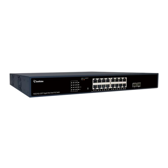
Note: If any of these items is found missing or damaged, please contact your local supplier for replacement. Front Panel The front panel consists of 16*10/100/1000 Mbps adaptive RJ-45 ports, 2*1000 Mbps SFP slots, and related indicators, as shown in the following figure: Figure 1. Front panel of GV-APOE161C... -
Page 3: Led Indicator
GV-APOE161C Port description: 10/100/1000 Mbps RJ-45 Ports ⚫ Supports 10 Mbps, 100 Mbps, or 1000 Mbps rate adaptation (Auto-MDI/MDIX), and each port has a corresponding indicator, that is, port indicators 1-16 as shown on the panel in the figure above. -
Page 4: Rear Panel
The rear panel of a Switch shows the AC power port. The power input ranges from 100 ~ 240V AC at 50/60 Hz. Figure 2. Rear panel of the GV-APOE161C AC power port This is an AC power socket, connect the negative plug of the power cord to this interface, and connect the positive plug to the AC power supply. -
Page 5: Mount Installation
Mount Installation Desktop Installation ➢ Place the bottom of the Switch face up on a large enough stable desktop. ➢ Tear off the attached sticky paper on the surface of the footpad and paste the footpad into the groove at the bottom of the chassis of the Switch to prevent external vibration. ➢... -
Page 6: Rackmount Installation
Rackmount Installation ➢ Check the grounding and stability of the EIA-19inch cabinet. ➢ Fix mounting ears to both sides of the front panel of the Switch using screws. Place the Switch on a bracket of the cabinet and move the Switch along the guide rails of the cabinet to a proper position. -
Page 7: Connecting To Gv-Ip Camera
Connecting to GV-IP Camera The switch can be connected to up to 16 GV-IP Cameras and 1 GV-NVR / VMS System. You can also extend the connection by connecting to another switch. Note: GV-NVR / VMS or a switch can connect to the RJ-45 ports or SFP ports. The maximum cable length for: ... -
Page 8: Accessing The Web Interface
Accessing the Web Interface Users can log in the Web interface to manage and set up the switch. 1. To access the Web user interface, type the default IP 192.168.0.250 into your Web browser. The login page appears. 2. Type the default username admin and password admin. Click Login In. 3. -
Page 9: Basic Setup
Basic Setup Refer to the following sections for the basic setup of the switch, including assigning an IP address and configuring port PoE. A. Assigning an IP Address Adopt one of the following alternatives to assign an IP address to the switch. Assigning a Fixed or Dynamic IP on the Web Interface 1. - Page 10 Assigning an IP Using GV-IP Device Utility 1. Make sure a PC and the switch are connected to the same LAN, and GV-IP Device Utility (V8.9.9 or later) is installed on the PC from our website. 2. On GV-IP Device Utility, click the button to search for the IP devices in the same LAN.
-
Page 11: Configuring Poe Port Using Gv-Ip Device Utility
B. Configuring PoE Port Using GV-IP Device Utility You can quickly access and configure the PoE port status of the devices connected to the switch by using GV-IP Device Utility. Follow the instructions below: 1. Make sure a PC and the switch are connected to the LAN, and GV-IP Device Utility (V8.9.9 or later) is installed on the PC from our website. -
Page 12: Loading Default Setting
Loading Default Setting If for any reason the device is not responding properly, you can reset it to its factory default settings either directly on the device or through its Web interface. Hardware 1. Turn on the switch. 2. Press and hold the Reset button on the front panel of the switch for 5 seconds until all the LED start blinking. -
Page 13: Web Interface
Web Interface 1. Select System Information > Device Management. 2. In the Device Management table, click Reboot to restart the switch, click Restore to restore the switch to its factory default configurations, or click Save Configure to restore default configurations while keeping the current settings. Note: After loading default by pressing the Reset button or from the Web interface, you may need to configure IP address and Password again. -
Page 14: Updating Firmware
Updating Firmware 1. Select System Information > Upgrade. This page appears. 2. Click Select File to select the firmware file. 3. Click OK on the popup message. The upgrade process starts. 4. After the firmware is successfully upgraded, the system will automatically log out and reboot.
Need help?
Do you have a question about the GV-APOE161C and is the answer not in the manual?
Questions and answers