Table of Contents
Advertisement
Quick Links
Advertisement
Table of Contents

Related Manuals for GeoVision GV-APOE0810


Summary of Contents for GeoVision GV-APOE0810
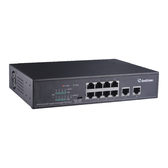
- Page 1 GV-APOE0810 10-Port 10/100/1000M Unmanaged PoE Switch with 8-Port PoE 1. Packing List 1. GV-APOE0810 4. Rack Mount Kit 2. AC Power Cord 5. Screws x 8 3. Rubber Feet x 4 Note: If any of these items is found missing or damaged, please contact your local supplier for replacement.
- Page 2 2. Front Panel The front panel consists of 10 10/100/1000 Mbps ports, 8 PoE and 2 uplink, LED indicators and the DIP switch. 2.1 LED Indicator Color/Status Description No power supply Orange System powered on No devices connected to the corresponding port Network through the corresponding port has been Orange successfully established at 10/100 Mbps.
- Page 3 2.2 DIP Switch The DIP switch can switch the system among the following three modes. [Default Mode] There is communication between all 10 ports, and power is supplied through the 8 PoE ports over cables of up to 100 m (328 ft) with a network bandwidth of 1000 Mbps per port.
- Page 4 4. Installation Prior to installing the PoE switch, please note the following: Only clean the switch when it is unplugged and with a dry cloth without involving any liquids. Do not place the switch near water or any damp area and prevent moisture from ...
- Page 5 4.2 Wall Mount Installation For wall mount, make sure to prepare 2 screws of 4 mm in length and 5.5 ~ 7 mm in diameter and prepare 2 screw anchors of matching size. 1. Drill two evenly-leveled holes on the desired wall that are 150 mm apart. 2.
- Page 6 5. Connecting to GV-IP Camera The switch can be connected to up to 8 GV-IP Camera and 1 GV-VMS / NVR / DVR System. You can also extend the connection by connecting to another switch. 6. Specifications For details, please see Datasheet. September 10, 2021...
Need help?
Do you have a question about the GV-APOE0810 and is the answer not in the manual?
Questions and answers