
Related Manuals for GeoVision GV-APOE0410-E


Summary of Contents for GeoVision GV-APOE0410-E
- Page 1 GV-PoE Switch GV-APOE0410-E User's Manual Before attempting to connect or operate this product, please read these instructions carefully and save this manual for future use. APOE0410E-A...
- Page 2 GeoVision. Every effort has been made to ensure that the information in this manual is accurate. GeoVision, Inc. makes no expressed or implied warranty of any kind and assumes no responsibility for errors or omissions. No liability is assumed for incidental or consequential damages arising from the use of the information or products contained herein.
-
Page 3: Table Of Contents
Contents Safety Precautions ........................i Chapter 1 Introduction to the User Guide ................1 1.1 Use ..........................1 1.2 User Manual Overview ..................1 Chapter 2 Product Introduction ..................... 2 2.1 Product Overview ....................2 2.2 Product Features....................2 2.3 Product Advantage ....................2 Chapter 3 Product Appearance Description ............... -
Page 4: Safety Precautions
Safety Precautions Note: Precision devices are built in the device, please handle them carefully to avoid violent vibration, which may affect the performance of the device. If you find that the equipment is damaged or any parts are lost in the process of transportation, please inform us, we will give you a proper solution as soon as possible. -
Page 5: Chapter 1 Introduction To The User Guide
Chapter 1 Introduction to the User Guide Thank you for purchasing our 4-Port Gigabit+2G SFP industrial grade Unmanaged PoE Switch! The device adopts no fan, low power consumption design, has the advantages of easy to use, compact and beautiful, simple installation. The product is designed to meet Ethernet standards, with lightning protection, static protection mechanism, operating temperature range of -40°C to 75°C, stable performance, safety and reliability, can be widely used in intelligent transportation, telecommunications,... -
Page 6: Chapter 2 Product Introduction
Chapter 2 Product Introduction 2.1 Product Overview GV-APOE0410-E is an industrial-grade, unmanaged PoE switch with 4 PoE+ 10/100/1000 BaseT(X) ports and 2 Gigabit SFP ports. The switch supports IEEE 802.3at Power over Ethernet standard with up to 30 W per port and a maximum power consumption of 125 W. - Page 7 High energy aluminum alloy roof heat conduction groove shell design Body size 110*90*46 mm, compact and light, full aluminum alloy high energy roof heat conduction groove shell design, better heat dissipation effect. DIN-Rail installation, simple and flexible DIN-Rail installation design, easy and quick installation, so that users reduce unnecessary installation time, save time cost.
-
Page 8: Chapter 3 Product Appearance Description
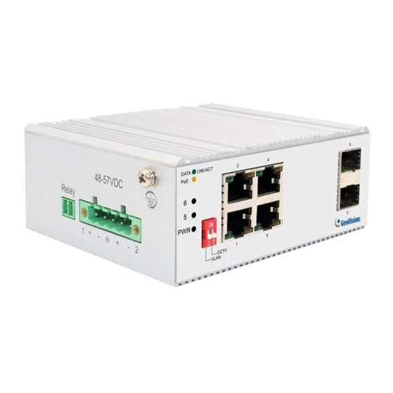
Chapter 3 Product Appearance Description 3.1 Front Panel The front panel consists of 4*10/100/1000Mbps adaptive RJ45 ports, 2*1000Mbps SFP slots and related indicators, as shown in the following figure: Figure 3-1 Front panel of the 4-Port Gigabit+2G SFP Switch 4-Port Gigabit+2G SFP Port description: 10/100/1000Mbps RJ45 Ports Supports 10Mbps, 100Mbps, or 1000Mbps rate adaptation, auto-MDI /MDIX, and each port has a corresponding indicator, that is, port indicators 1-4 as shown on the... -
Page 9: Dip Switch Indicator Status Description
3.2 Dip Switch Indicator Status Description... -
Page 10: Led Indicator
3.3 LED Indicator The LED indicators of the Switch are shown in the following table. Users can monitor the work and running status of the Switch conveniently and quickly through the following indicators: Color Function Off: No Power supply. Green Light: Indicates the Switch has power. - Page 11 Relay port:Alarm port, support machine abnormal alarm function. This interface needs to be connected to an external alarm device. When the machine starts abnormally or when the power is on, the internal relay will close and output the alarm signal in time, which has the function of automatic alarm, safety protection and isolation conversion in the circuit.
-
Page 12: Chapter 4 Installation Guide
Chapter 4 Installation Guide This chapter helps users correctly install and safely use Switches. 4.1 Installation Precautions Precautions: To avoid equipment damage and personal injury, observe the following precautions: ➢ The Switch room should be dry and ventilated, free from corrosive gases and strong electromagnetic interference;... -
Page 13: Installation
➢ Power supply: 48V to 57V DC power supply; ➢ Environment: operating temperature: -40°C to 75 °C relative humidity: 5% to 95%. 4.3 Installation DIN-Rail Installation The 45mm standard DIN-Rail installation is very convenient for most industrial applications. The installation steps are as follows: ➢... - Page 14 Figure 4-2 Schematic diagram of industrial machine guide rail disassembly Power on ➢ Power on: First insert the power terminal of the power cable into the power port of the device, then plug in the power plug and power on. After the Switch is started, the Switch automatically initializes.
- Page 15 Schematic diagram of wall mounted installation of industrial machine ➢ Remove the DIN-Rail mounting plate on the rear board of the Switch; ➢ Install the wall mounting board on the Switch as shown below. ➢ Four wall screws are required to mount the Switch on the wall, as shown in the figure above.
Need help?
Do you have a question about the GV-APOE0410-E and is the answer not in the manual?
Questions and answers