Table of Contents
Advertisement
Quick Links
GV-APOE0400
with 4-Port PoE
1. Packing List
1. GV-APOE0400
2. AC Power Cord
3. Rubber Feet x 4
Note: If any of these items is found missing or damaged, please contact your local
supplier for replacement.
2. Introduction
GV-APOE0400 is a 6-port 10/100 Mbps unmanaged PoE Switch with 4 PSE/PoE ports and 2
uplink ports. The switch supports IEEE 802.3at Power over Ethernet standard, with up to 32
W per port and a maximum power consumption of 65 W. In addition to not requiring special
network cables for connecting your powered devices (PD), such as IP cameras, its CCTV
mode also allows power supply over cables of up to 250 m (820 ft) in length, at 10 Mbps.
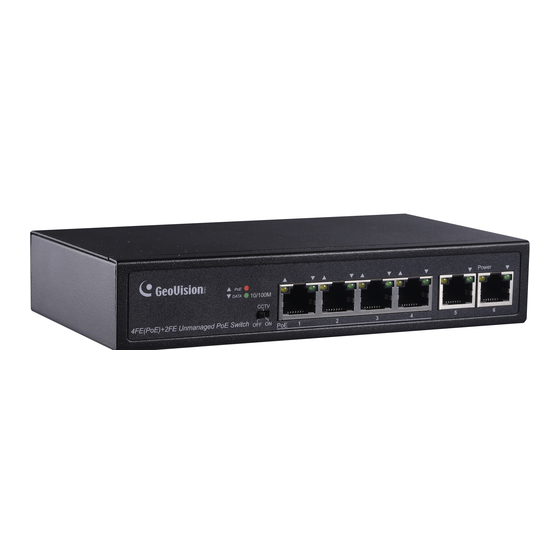
3. Front Panel
The front panel consists of 6 10/100 Mbps ports, 4 PoE and 2 uplink, LED indicators and the
DIP switch.
December 28, 2018
6-Port 10/100 Mbps Unmanaged PoE Switch
1
Advertisement
Table of Contents

Related Manuals for GeoVision GV-APOE0400


Summary of Contents for GeoVision GV-APOE0400
-
Page 1: Packing List
2. Introduction GV-APOE0400 is a 6-port 10/100 Mbps unmanaged PoE Switch with 4 PSE/PoE ports and 2 uplink ports. The switch supports IEEE 802.3at Power over Ethernet standard, with up to 32 W per port and a maximum power consumption of 65 W. In addition to not requiring special network cables for connecting your powered devices (PD), such as IP cameras, its CCTV mode also allows power supply over cables of up to 250 m (820 ft) in length, at 10 Mbps. -
Page 2: Led Indicators
3.1 LED Indicators Color/Status Description No power supply Power Orange System powered on No devices connected to the corresponding port Network through the corresponding port has been Green successfully established DATA Data currently being sent through the Blinking Green corresponding port No PoE powered devices (PD) connected At least one device successfully powered through Orange... -
Page 3: Installation
5. Installation Prior to installing the PoE switch, please note the following: Only clean the switch when it is unplugged and with a dry cloth without involving any liquids. Do not place the switch near water or any damp area and prevent moisture from ... -
Page 4: Wall Mount Installation
3. Insert the two-self prepared screws into the screw anchors and tighten to the point where there are about 1.5 mm left hanging out, as illustrated. 4. Hang the GV-APOE0400 onto the screws with all 6 of its port pointing downward, as illustrated. - Page 5 6. Connecting up to 4 GV-IP Devices and 1 GV-VMS/DVR/NVR System Through twisted pair cables, the switch can be connected to up to 4 GV-IP Devices and 1 GV-VMS/NVR/DVR System. You can also extend the connections by connecting to other switches.
-
Page 6: Specifications
7. Specifications Ethernet Layer Supported Ports 4 x PoE+ ports Number of Ports 6 x 10/100 RJ-45 ports: 2 x uplink ports Performance MAC Address Buffer Memory 768 K bits Transmission Method Store and Forward 10BaseT Cat. 5 UTP/STP Transmission Media 100BaseTX Cat. - Page 7 Standards and Regulatory IEEE802.3at PoE+ / PSE IEEE 802.3 10BaseT Standards IEEE 802.3u 100BaseTX IEEE 802.3x Flow Control Regulatory CE, FCC Class A, RoHS compliant Note: Specifications are subject to change without prior notice. December 28, 2018...
Need help?
Do you have a question about the GV-APOE0400 and is the answer not in the manual?
Questions and answers