Advertisement
Quick Links
ITV1-TFU21
Installation and Maintenance Manual
Electro-Pneumatic Regulator
Series ITV10**-*******-X440
ITV10**-*4*****-X441
II 3G Ex nA IIC T5 Gc X 0°C ≤ Ta ≤ 50°C
II 3D Ex tc IIIC T66°C Dc X IP65
1 Safety Instructions
This manual contains essential information for the protection of users and
others from possible injury and/or equipment damage.
Read this manual before using the product, to ensure correct handling,
and read the manuals of related apparatus before use.
Keep this manual in a safe place for future reference.
These instructions indicate the level of potential hazard by label of
"Caution", "Warning" or "Danger", followed by important safety
information which must be carefully followed.
To ensure safety of personnel and equipment the safety instructions in
this manual and the product catalogue must be observed, along with
other relevant safety practices.
Indicates a hazard with a low level of risk, which if
Caution
not avoided, could result in minor or moderate
injury.
Indicates a hazard with a medium level of risk,
Warning
which if not avoided, could result in death or
serious injury.
Indicates a hazard with a high level of risk, which if
Danger
not avoided, will result in death or serious injury.
Electromagnetic compatibility:
This product is class A equipment intended for use in an industrial
environment.
There
may
be
potential
difficulties
in
electromagnetic compatibility in other environments due to conducted as
well as radiated disturbances.
The compatibility of pneumatic equipment is the responsibility of
the person who designs the pneumatic system or decides its
specifications.
Since the products specified here can be used in various operating
conditions, their compatibility with the specific pneumatic system must
be based on specifications or after analysis and/or tests to meet specific
requirements.
Only trained personnel should operate pneumatically operated
machinery and equipment.
Compressed air can be dangerous if an operator is unfamiliar with it.
Assembly, handling or repair of pneumatic systems should be performed
by trained and experienced personnel.
Do not service machinery/equipment or attempt to remove
components until safety is confirmed.
1)Inspection and maintenance of machinery/equipment should only be
performed after confirmation of safe locked-out control positions.
2)When equipment is to be removed, confirm the safety process as
mentioned above. Switch off air and electrical supplies and exhaust all
residual compressed air in the system.
3)Before machinery/equipment is re-started, ensure all safety measures
to prevent sudden movement of cylinders etc. (Supply air into the system
gradually to create back pressure, i.e. incorporate a soft-start valve).
Do not use this product outside of the specifications. Contact SMC
if it is to be used in any of the following conditions:
1)Conditions and environments beyond the given specifications, or if the
product is to be used outdoors.
2)Installations in conjunction with atomic energy, railway, air navigation,
vehicles, medical equipment, food and beverage, recreation equipment,
emergency stop circuits, press applications, or safety equipment.
3)An application, which has the possibility of having negative effects on
people, property, or animals, requiring special safety analysis.
1 Safety Instructions (continued)
Ensure that the air supply system is filtered to 5 microns.
ATEX Marking Description
II 3G Ex nA IIC T5 Gc X 0°C ≤ Ta ≤ 50°C
II 3D Ex tc IIIC T66°C Dc X IP65
Equipment Group II
3D - Category 3 for Dust
tc – Protected by enclosure
3G - Category 3 for Gas
Ex – European standards apply
IIIC – For all types of dust
nA – Non-sparking apparatus
T66°C – Max. surface temperature
IIC – For all types of gas
Dc – Equipment Protection Level
T5 – Temperature classification
X – Special conditions for safe
Gc – Equipment Protection Level
use, see instructions
Ta – Ambient temperature
IP65 – Enclosure protection rating
Special Conditions for safe use
The ITV unit should be used within the range of specifications given below.
If labelled with X, special conditions for safe use apply:
1. Protect the product from sources of heat which can generate surface
temperatures higher than the temperature classification.
2. Protect the product and cables against all impact or mechanical
damage.
3. Protect the product from direct sunlight or UV light using a suitable
protective cover.
4. Do not disconnect the M12 connector before first switching off the
power supply.
6. Use only a damp cloth to clean the product body, to avoid an
electrostatic charge.
7. Provide suitable grounding of the product body to avoid electrostatic
charging.
2 Specifications
Model
ITV101*
ITV103*
ensuring
Min. supply pressure
(Set pressure) + 0.1 MPa
Max. supply pressure
0.2 MPa
0.005 ~
Set pressure range
0.1 MPa
0.5 MPa
Supply voltage
24 VDC±10%, 12 to 15 VDC
24 VDC
Max. 120 mA
Current
consumption
12 VDC
Max. 180 mA
Current
Note1
4-20 mADC, 0-20 mADC
Input signal
Voltage
0-5 VDC, 0-10 VDC
Max. 250
Current
Input
impedance
Voltage
Approx. 10 k
4-20 mADC - Sink type (-X440)
Current
4-20 mADC - Source type (-X441)
Output signal
Voltage
1-5 VDC (Load impedance: max. 1k)
NPN – Open collector: 30 V 30 mA
Switch
PNP – Open collector: 30 mA
Linearity
Max. ±1%F.S.
Hysteresis
Max. 0.5%F.S.
Repeatability
Max. ±0.5%F.S.
Sensitivity
Max. 0.2%F.S.
Temperature characteristics
Max. ±0.12%F.S./°C
Operating temperature
0~50°C (without condensation)
Accuracy
Pressure
Minimum
MPa: 0.001, kgf/cm
display
Unit
PSI: 0.1
Protection structure
Main unit: IP65, Cable connector: IP67
II 3G Ex nA IIC T5 Gc X 0°C ≤ Ta ≤ 50°C
Explosion Protection
II 3D Ex tc IIIC T66°C Dc X IP65
Table 1.
Note 1: Two wire control, 4 to 20 mADC and 0 to 20 mADC are not available. Supply
voltage of 12-15 VDC or 24 VDC is required.
Note 2: 1 PSI is the minimum unit on ITV105*.
3 Operation Principle
When the input signal increases the supply solenoid valve turns on and
the exhaust solenoid valve turns off. Supply pressure is passed to the
pilot valve through the supply solenoid valve. The pilot valve will open
the main valve allowing partial supply pressure to pass to the out port. The
pressure sensor will provide output pressure feedback to the control
circuit . The control circuit will balance the input signal and output
pressure to ensure that the output pressure remains proportional to the
input signal.
Fig. 1 - Control diagram
Fig. 2 - Schematic diagram
4 Wiring
ITV105*
Connect the cable to the connector on the main unit as shown in the
following diagram. Take precautions, as incorrect wiring will damage the
1.0 MPa
unit. Use a DC power supply capable of supplying the necessary power
0.005 ~
0.005 ~
0.9 MPa
requirements with minimal ripple.
Brown
Brown
White
Blue
Blue
White
Black
Black
Note
Blue
Main unit
Black
Current signal type
±3% F.S
Vs:
Power supply
24 VDC
2
: 0.01, bar: 0.01,
(Note2)
, kPa: 1
12-15 VDC
A:
Input signal
4 to 20 mADC
0 to 20 mADC
Fig. 4 - Wiring diagrams
5 Setting the Regulator
When the 'Set' key is operated the minimum/maximum pressure will be
present at the outlet port. When primary pressure is applied to the regulator
minimum pressure will be present at the outlet port.
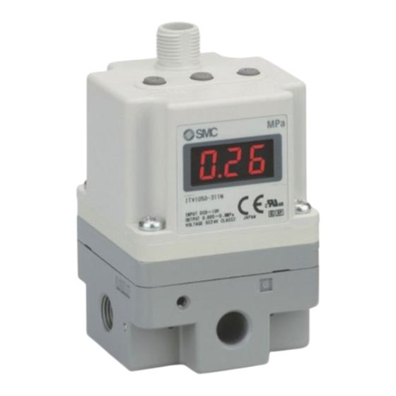
Electrical Connector
Set Key
Down Key
Air Supply port
• Release 'Key Lock 'as explained in section 'Key-Lock Function'
• After releasing key lock, press the 'Set' key again to move to F-1
• To set the minimum pressure (display shows F-1) use up/down keys and
press the 'Set' key to 'Lock' the setting.
• To set the maximum pressure (display shows F-2) use up/down keys and
press the 'Set' key to 'Lock' the setting.
Note 1: If the above sequence has been followed correctly, the settings will
complete automatically.
Note 2: If only setting minimum pressure, when pressure is 'Set', pressing
the set button once more will 'skip' to the next step.
6 Key-Lock Function
The keys will be locked and cannot be operated when the power is
supplied. 'Loc' is displayed when any keys are pushed.
• Key-Lock Release
• Press the 'Down' key for 2 seconds or more.
• Display will flash 'Loc' (locked).
• Press the 'Set' key to unlock.
Note: To cancel press the 'Up' key.
Power supply
• Key-Lock
Note: The right angle type
Input signal
• Press the 'Up' key for 2 seconds or more.
GND (Common)
connector extends to
Monitor output
• Display will flash 'unL' (unlocked).
the left side (over the
• Press the 'Set' key to lock.
supply port side)
Brown
Note: To cancel press the 'Down' key.
White
7 'Error' Display
If an abnormality is detected by the ITV the LED display will show 'Er'
followed by a code number. Isolate the power supply and ascertain the
problem and solve. Re-instate the power supply after correcting any fault.
Error codes are as shown in the table below.
Brown
Brown
Blue
Blue
No
White
White
1
Black
Black
2
3
4
Voltage signal type
5
Vs:
Power supply
24 VDC
6
12-15 VDC
Vin:
Input signal
0 to 5 VDC
8 Reset Function
0 to 10 VDC
• Press the 'Up' and 'Down' keys (Fig 6) simultaneously for 3 seconds or
more.
• Display shows 'RES'.
• Release keys to reset minimum pressure and maximum pressure.
UP Key
LED Display
Air Outlet port
Fig. 6 - Key features of the ITV
.
Content
Display
Input signal is outside the specification
Er 1
EEProm read/write error
Er 2
Memory read/write error
Er 3
Solenoid valve fault
Er 4
Switch output over-current
Er 5
Outside of the Zero-clear range
Er 6
Advertisement

Subscribe to Our Youtube Channel
Related Manuals for SMC Networks ITV10-X440 Series


Summary of Contents for SMC Networks ITV10-X440 Series
- Page 1 ITV1-TFU21 1 Safety Instructions (continued) 3 Operation Principle 5 Setting the Regulator When the input signal increases the supply solenoid valve turns on and the exhaust solenoid valve turns off. Supply pressure is passed to the Ensure that the air supply system is filtered to 5 microns. When the ‘Set’...
- Page 2 ITV1-TFU21 9 Zero-clear Function • Press the ‘Set’ keys (Fig 6) together for 2 seconds or more. • Press the ‘Up’ and ‘Down’ keys (Fig Display shows ‘F03’. • Press the ‘Set’ keys (Fig Display shows ‘OcL’(Flashing). • Press the ‘Up’ and ‘Down’ keys (Fig 6) simultaneously.
Need help?
Do you have a question about the ITV10-X440 Series and is the answer not in the manual?
Questions and answers