Advertisement
Quick Links
www.ti.com
EVM User's Guide: F29H85X-SOM-EVM
F29H85X controlSOM Evaluation Board
Description
F29H85X-SOM-EVM is an evaluation and
development board for TI C2000
of F29H85x and F29P58x devices. Its system-on-
module design with three 120-pin high-speed/high-
density connectors is ideal for initial evaluation and
prototyping. An
XDS110ISO-EVM
required for evaluation of the F29H85X-SOM-EVM,
and can be purchased separately.
Get Started
1. Order the F29H85X controlSOM evaluation board
(EVM).
2. Order the XDS110 plug-in board
EVM) and any optional adapter and base board
hardware.
SPRUJE4B – AUGUST 2024 – REVISED DECEMBER 2024
Submit Document Feedback
™
MCU series
debug probe is
(XDS110ISO-
F29H85X-SOM-EVM
Copyright © 2024 Texas Instruments Incorporated
3. Download the latest Code Composer Studio
Theia
integrated development environment (IDE)
and
MCU_SDK_F29H85x
kit.
4. Read the Quick Start Setup chapter in this user's
guide to get started!
Features
•
Three 120-pin controlSOM high-speed/high-
density connectors
•
Analog I/O, digital I/O and JTAG signals at board
interface
•
Power management IC for safety applications
•
Free download of
Code Composer Studio Theia
IDE
•
Free download of
MCU_SDK_F29H85x
drivers and example projects
F29H85X controlSOM Evaluation Board
Description
™
software development
for device
1
Advertisement

Related Manuals for Texas Instruments controlSOM F29H85X


Summary of Contents for Texas Instruments controlSOM F29H85X
- Page 1 Free download of MCU_SDK_F29H85x for device EVM) and any optional adapter and base board drivers and example projects hardware. F29H85X-SOM-EVM SPRUJE4B – AUGUST 2024 – REVISED DECEMBER 2024 F29H85X controlSOM Evaluation Board Submit Document Feedback Copyright © 2024 Texas Instruments Incorporated...
- Page 2 Full compliance to safety, EMI/EMC, and other regulations are left to the designer of the customer’s system. F29H85X controlSOM Evaluation Board SPRUJE4B – AUGUST 2024 – REVISED DECEMBER 2024 Submit Document Feedback Copyright © 2024 Texas Instruments Incorporated...
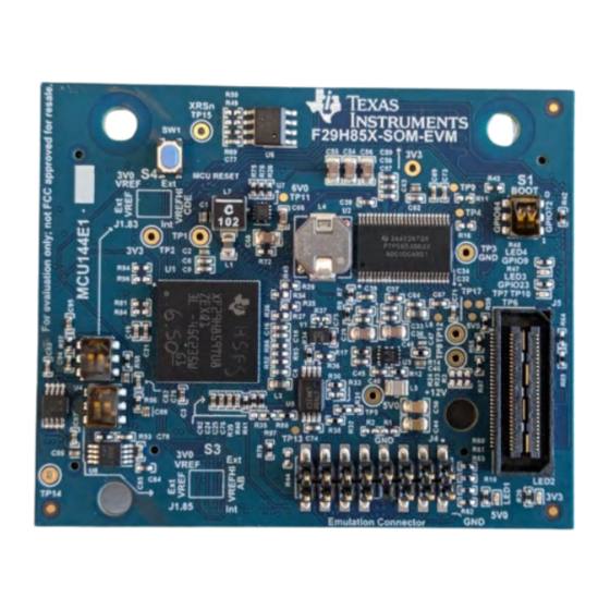
- Page 3 Evaluation Module Overview Figure 1-2. Key Components on the controlSOM - Front SPRUJE4B – AUGUST 2024 – REVISED DECEMBER 2024 F29H85X controlSOM Evaluation Board Submit Document Feedback Copyright © 2024 Texas Instruments Incorporated...
- Page 4 For a full list of device features, refer to the F29H85x and F29P58x Real-Time Microcontrollers data sheet and F29H85x and F29P58x Real-Time Microcontrollers Technical Reference Manual. F29H85X controlSOM Evaluation Board SPRUJE4B – AUGUST 2024 – REVISED DECEMBER 2024 Submit Document Feedback Copyright © 2024 Texas Instruments Incorporated...
- Page 5 5. Verify the power status LEDs (LED1 and LED2) on the controlSOM are turned on. 6. The controlSOM is ready for use. Follow the steps in Software to get started developing software. SPRUJE4B – AUGUST 2024 – REVISED DECEMBER 2024 F29H85X controlSOM Evaluation Board Submit Document Feedback Copyright © 2024 Texas Instruments Incorporated...
- Page 6 J1.7 J1.13 GPIO1 GPIO3 J1.9 J1.15 GPIO0 A7/E25/GPIO225/ J1.118 J1.117 A1/C25/CMP7P/ CMP9P/CMP2N CMP4N A6/E24/GPIO224/ J1.120 J1.119 A0/DACOUT1/C24/ CMP2P/CMP12N CMP4P/CMP9P F29H85X controlSOM Evaluation Board SPRUJE4B – AUGUST 2024 – REVISED DECEMBER 2024 Submit Document Feedback Copyright © 2024 Texas Instruments Incorporated...
- Page 7 10. Verify the power status LEDs (LED1 and LED2) on the controlSOM are turned on. 11. The controlSOM is ready for use. Follow the steps in Software to get started developing software. SPRUJE4B – AUGUST 2024 – REVISED DECEMBER 2024 F29H85X controlSOM Evaluation Board Submit Document Feedback Copyright © 2024 Texas Instruments Incorporated...
- Page 8 5. Ensure the controlSOM is correctly oriented. The J1 header on the controlSOM should connect with the J1 header on the base board. 6. Connect the XDS110ISO-EVM into the XDS Debug Header (J4) of the controlSOM. F29H85X controlSOM Evaluation Board SPRUJE4B – AUGUST 2024 – REVISED DECEMBER 2024 Submit Document Feedback Copyright © 2024 Texas Instruments Incorporated...
- Page 9 Table 2-2. F29H85x controlSOM Voltage Rail Outputs controlSOM Voltage Rail Voltage Output (V) Maximum Current Rating (mA) 3V3_OUT 5V0_OUT_CAN SPRUJE4B – AUGUST 2024 – REVISED DECEMBER 2024 F29H85X controlSOM Evaluation Board Submit Document Feedback Copyright © 2024 Texas Instruments Incorporated...
- Page 10 XDS110ISO-EVM to identify the hardware during a debug session. This I2C EEPROM is not accessible by the F29H85x device. 3V3_OUT 0.1uF 4.70k 4.70k EEPROM_I2CSCL EEPROM_I2CSDA Figure 2-5. Board ID EEPROM F29H85X controlSOM Evaluation Board SPRUJE4B – AUGUST 2024 – REVISED DECEMBER 2024 Submit Document Feedback Copyright © 2024 Texas Instruments Incorporated...
- Page 11 GPIO84 Boot Mode Boot from parallel GPIO Boot from UART / Wait Mode Boot from CAN Boot from Flash SPRUJE4B – AUGUST 2024 – REVISED DECEMBER 2024 F29H85X controlSOM Evaluation Board Submit Document Feedback Copyright © 2024 Texas Instruments Incorporated...
- Page 12 DOWN Internal VREF DOWN External VREF from J1.85 pin On-board 3.0V reference Figure 2-8. ADCC/ADCD/ADCE VREF Mode Switch (S4) F29H85X controlSOM Evaluation Board SPRUJE4B – AUGUST 2024 – REVISED DECEMBER 2024 Submit Document Feedback Copyright © 2024 Texas Instruments Incorporated...
- Page 13 MCU_ESC_RX1_DATA1 MCU_ESC_RX1_DATA2 MCU_GPIO67 MCU_GPIO68 MCU_CANTX MCU_CANRX Figure 2-9. MCAN-A Boot Selection Resistors Figure 2-10. MCAN-A Boot Selection Resistor Locations SPRUJE4B – AUGUST 2024 – REVISED DECEMBER 2024 F29H85X controlSOM Evaluation Board Submit Document Feedback Copyright © 2024 Texas Instruments Incorporated...
- Page 14 MCU_GPI O 7 SOM_GPIO50 SOM_GPIO7 DLT_GPIO50 DLT_GPIO7 Figure 2-11. FSI DLT Selection Resistors Figure 2-12. FSI DLT Selection Resistor Locations (Top) F29H85X controlSOM Evaluation Board SPRUJE4B – AUGUST 2024 – REVISED DECEMBER 2024 Submit Document Feedback Copyright © 2024 Texas Instruments Incorporated...
- Page 15 Remove all resistors on R52, R86, R93, R55, R88, R94, R81, and R89. Populate all 0-ohm resistors on R82, R90, R95, R83, R91, R96, R84, and R92. SPRUJE4B – AUGUST 2024 – REVISED DECEMBER 2024 F29H85X controlSOM Evaluation Board Submit Document Feedback Copyright © 2024 Texas Instruments Incorporated...
- Page 16 EVM Connection VSYS_3V3_LDO1 IO_TGT_V MCU_TMS MCU_TCK MCU_TDI MCU_TDO UART0_RXD MCU_SCI_RX MCU_SCI_TX UART0_TXD I2C0_SDA EE_I2CSDA EE_I2CSCL I2C0_SCL SPI3_CLK DAC_SPI_SCLK DAC_SPI_PICO SPI3_D0 F29H85X controlSOM Evaluation Board SPRUJE4B – AUGUST 2024 – REVISED DECEMBER 2024 Submit Document Feedback Copyright © 2024 Texas Instruments Incorporated...
- Page 17 GPIO8 ohm resistor TRC_DATA[1][12] or (FSITX0_CLK) TRC_DATA[2][2] TRC_CLK[0] TRC_DATA[0][13] or TRC_DATA[3][3] TRC_CLK[1] TRC_DATA[0][33] or GPIO6 (FSITX0_D0) TRC_DATA[1][13] or TRC_DATA[2][3] SPRUJE4B – AUGUST 2024 – REVISED DECEMBER 2024 F29H85X controlSOM Evaluation Board Submit Document Feedback Copyright © 2024 Texas Instruments Incorporated...
- Page 18 TRC_DATA[1][4] or TRC_DATA[0][39] or GPIO50 (FSITX1_D1) TRC_DATA[0][24] TRC_DATA[1][19] or TRC_DATA[2][9] TRC_DATA[0][5] TRC_DATA[1][5] or TRC_DATA[0][25] TRC_DATA[0][6] TRC_CLK[3] TRC_DATA[1][6] or TRC_CLK[2] TRC_DATA[0][26] F29H85X controlSOM Evaluation Board SPRUJE4B – AUGUST 2024 – REVISED DECEMBER 2024 Submit Document Feedback Copyright © 2024 Texas Instruments Incorporated...
- Page 19 "JTAG/SWD/cJTAG Mode" drop-down. Alternatively, a working target configuration file is included in all the F29 SDK examples. This file can be used without modifications. SPRUJE4B – AUGUST 2024 – REVISED DECEMBER 2024 F29H85X controlSOM Evaluation Board Submit Document Feedback Copyright © 2024 Texas Instruments Incorporated...
- Page 20 MCU GPIO19/ERRORSTS output TP14 VDDA_3V3 Filtered MCU VDDA supply TP15 MCU_XRSn MCU reset (XRSn) pin TP16 3V3_OUT PMIC 3.3V output (LDO1_OUT) F29H85X controlSOM Evaluation Board SPRUJE4B – AUGUST 2024 – REVISED DECEMBER 2024 Submit Document Feedback Copyright © 2024 Texas Instruments Incorporated...
- Page 21 This kit is assumed to run at standard room conditions. Standard ambient temperature and pressure (SATP) with moderate-to-low humidity is assumed. SPRUJE4B – AUGUST 2024 – REVISED DECEMBER 2024 F29H85X controlSOM Evaluation Board Submit Document Feedback Copyright © 2024 Texas Instruments Incorporated...
- Page 22 7. Select the "led_ex1_blinky" project from the "Discovered Projects" list and click "Finish" to import the project into the workspace 8. Right-click on the project name and select "Build Configurations -> CPU1_FLASH" F29H85X controlSOM Evaluation Board SPRUJE4B – AUGUST 2024 – REVISED DECEMBER 2024 Submit Document Feedback Copyright © 2024 Texas Instruments Incorporated...
- Page 23 FLASH configuration", and launches the target configuration. Figure 3-2. Debug Project Selection 10. Select "Texas Instruments XDS110 USB Debug Probe_0/C29xx_CPU1" as the core 11. Navigate to Debug (left side of screen) and select the blue play button to run the example SPRUJE4B –...
- Page 24 Software www.ti.com Figure 3-3. Run Selection 12. Observe the LED blinking on the controlSOM F29H85X controlSOM Evaluation Board SPRUJE4B – AUGUST 2024 – REVISED DECEMBER 2024 Submit Document Feedback Copyright © 2024 Texas Instruments Incorporated...
- Page 25 The board layout source files are included in the F29H85X-SOM-EVM design files. 4.3 Bill of Materials (BOM) The BOM is included in the F29H85X-SOM-EVM design files. SPRUJE4B – AUGUST 2024 – REVISED DECEMBER 2024 F29H85X controlSOM Evaluation Board Submit Document Feedback Copyright © 2024 Texas Instruments Incorporated...
- Page 26 Internal oscillator (INTOSC2) defaults to 6MHz: in early F29H85x devices INTOSC2 is untrimmed and defaults to 6MHz. F29H85X-SOM-EVMs built with these early F29H85x MCU samples are labeled as MCU144E1-001. F29H85X controlSOM Evaluation Board SPRUJE4B – AUGUST 2024 – REVISED DECEMBER 2024 Submit Document Feedback Copyright © 2024 Texas Instruments Incorporated...
- Page 27 Replace R53 and R57 on the on the board with 0Ω resistors. • Remove C78, C79, C94, and C95 SPRUJE4B – AUGUST 2024 – REVISED DECEMBER 2024 F29H85X controlSOM Evaluation Board Submit Document Feedback Copyright © 2024 Texas Instruments Incorporated...
- Page 28 Figure 5-1. Component Location For ADC VREF Modification Refer to Section 2.4.2 for more information on S3 and S4. F29H85X controlSOM Evaluation Board SPRUJE4B – AUGUST 2024 – REVISED DECEMBER 2024 Submit Document Feedback Copyright © 2024 Texas Instruments Incorporated...
- Page 29 Add blue wire between R1, R2, and U7.5 as shown in Figure 5-2. Figure 5-2. Hardware Modification for Power-Up Advisory SPRUJE4B – AUGUST 2024 – REVISED DECEMBER 2024 F29H85X controlSOM Evaluation Board Submit Document Feedback Copyright © 2024 Texas Instruments Incorporated...
- Page 30 F29H85x and F29P58x Real-Time Microcontrollers Technical Reference Manual • Code Composer Studio Integrated Development Environment (IDE) • MCU-SDK-F29H85x Development Kit F29H85X controlSOM Evaluation Board SPRUJE4B – AUGUST 2024 – REVISED DECEMBER 2024 Submit Document Feedback Copyright © 2024 Texas Instruments Incorporated...
- Page 31 "This hardware modification has been implemented on all MCU144E1-002 assemblies" to "This hardware modification has been implemented on all MCU144E1-002 and MCU144E1-003 assemblies"...............................27 SPRUJE4B – AUGUST 2024 – REVISED DECEMBER 2024 F29H85X controlSOM Evaluation Board Submit Document Feedback Copyright © 2024 Texas Instruments Incorporated...
- Page 32 STANDARD TERMS FOR EVALUATION MODULES Delivery: TI delivers TI evaluation boards, kits, or modules, including any accompanying demonstration software, components, and/or documentation which may be provided together or separately (collectively, an “EVM” or “EVMs”) to the User (“User”) in accordance with the terms set forth herein.
- Page 33 www.ti.com Regulatory Notices: 3.1 United States 3.1.1 Notice applicable to EVMs not FCC-Approved: FCC NOTICE: This kit is designed to allow product developers to evaluate electronic components, circuitry, or software associated with the kit to determine whether to incorporate such items in a finished product and software developers to write software applications for use with the end product.
- Page 34 www.ti.com Concernant les EVMs avec antennes détachables Conformément à la réglementation d'Industrie Canada, le présent émetteur radio peut fonctionner avec une antenne d'un type et d'un gain maximal (ou inférieur) approuvé pour l'émetteur par Industrie Canada. Dans le but de réduire les risques de brouillage radioélectrique à...
- Page 35 www.ti.com EVM Use Restrictions and Warnings: 4.1 EVMS ARE NOT FOR USE IN FUNCTIONAL SAFETY AND/OR SAFETY CRITICAL EVALUATIONS, INCLUDING BUT NOT LIMITED TO EVALUATIONS OF LIFE SUPPORT APPLICATIONS. 4.2 User must read and apply the user guide and other available documentation provided by TI regarding the EVM prior to handling or using the EVM, including without limitation any warning or restriction notices.
- Page 36 Notwithstanding the foregoing, any judgment may be enforced in any United States or foreign court, and TI may seek injunctive relief in any United States or foreign court. Mailing Address: Texas Instruments, Post Office Box 655303, Dallas, Texas 75265 Copyright © 2023, Texas Instruments Incorporated...
- Page 37 TI products. TI’s provision of these resources does not expand or otherwise alter TI’s applicable warranties or warranty disclaimers for TI products. TI objects to and rejects any additional or different terms you may have proposed. IMPORTANT NOTICE Mailing Address: Texas Instruments, Post Office Box 655303, Dallas, Texas 75265 Copyright © 2024, Texas Instruments Incorporated...
Need help?
Do you have a question about the controlSOM F29H85X and is the answer not in the manual?
Questions and answers