
Related Manuals for Texas Instruments FDC2114


Summary of Contents for Texas Instruments FDC2114
- Page 1 FDC2114 and FDC2214 EVM User’s Guide User's Guide Literature Number: SNOU138 June 2015...
-
Page 2: Table Of Contents
3.6.5 Displaying Measurement Data Statistics ................. 3.6.6 Navigating the GUI's Data Buffer ..................Updating the EVM Firmware ................FDC2114/2214 EVM Schematics and Layout ........................Bill of Materials .......................... Revision History Table of Contents SNOU138 – June 2015 Submit Documentation Feedback... - Page 3 Selecting the External Oscillator and Entering its Frequency ................Selecting F for Channel Measurements ........ Entering the Sensor Inductor Values for Calculating Capacitance Measurements ..............Updating Input Measurement Gain for FDC2114 ..............Updating Input Measurement Offset for FDC2114 ..............Detecting Optimal I from the Configuration Page drive ................
- Page 4 Layout Top Layer – Signals and Components ..................Layout Mid-Layer 1 – Ground Plane ................Mid-Layer 2 – Signals and Power Plane ................... Layout Bottom Layer – Signals Plane List of Figures SNOU138 – June 2015 Submit Documentation Feedback Copyright © 2015, Texas Instruments Incorporated...
- Page 5 List of Tables ....................BOM for FDC2114 EVM ....................BOM for FDC2214 EVM SNOU138 – June 2015 List of Tables Submit Documentation Feedback Copyright © 2015, Texas Instruments Incorporated...
-
Page 6: Overview
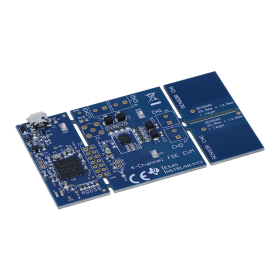
The FDC2114/2214 EVM demonstrates the use of capacitive sensing technology to sense and measure the presence or position of target objects. The EVM contains two example LC tank sensors that are connected to the FDC2114/2214 input channels. The latter is controlled by an MSP430, which interfaces to a host computer. -
Page 7: Software Setup
2. Extract the downloaded ZIP file 3. Run the included executable 4. Follow all directions from the installer Figure 2. GUI Installer Welcome Page SNOU138 – June 2015 FDC2114 and FDC2214 EVM User’s Guide Submit Documentation Feedback Copyright © 2015, Texas Instruments Incorporated... -
Page 8: Gui Installer License Agreement
6. Select the installation directory. If the user installing the software is not a system administrator a directory not with “Program Files” should be chosen instead of the default. Figure 4. GUI Installer Installation Directory FDC2114 and FDC2214 EVM User’s Guide SNOU138 – June 2015 Submit Documentation Feedback... -
Page 9: Gui Installer Copying Files
If running Windows 8 or 8.1, the PC must be started in a “Safe” mode to install the unsigned driver. Figure 6. EVM Driver Installer Welcome Page 9. Wait for the driver to install SNOU138 – June 2015 FDC2114 and FDC2214 EVM User’s Guide Submit Documentation Feedback Copyright © 2015, Texas Instruments Incorporated... -
Page 10: Evm Driver Installer In Progress
10. Click “Finish” after the driver has been installed Figure 8. EVM Driver Installer Complete 11. Click “Finish” to complete the software installation FDC2114 and FDC2214 EVM User’s Guide SNOU138 – June 2015 Submit Documentation Feedback Copyright © 2015, Texas Instruments Incorporated... -
Page 11: Gui Operation
6. Splash screen will appear for at least two seconds. • Slower PC’s may show a blank splash screen without any texts for up to 20 seconds SNOU138 – June 2015 FDC2114 and FDC2214 EVM User’s Guide Submit Documentation Feedback Copyright © 2015, Texas Instruments Incorporated... -
Page 12: Connecting The Evm
1. Attach the EVM to the computer via a micro USB cable 2. The GUI always shows the connection status on the bottom left corner of the GUI FDC2114 and FDC2214 EVM User’s Guide SNOU138 – June 2015 Submit Documentation Feedback... -
Page 13: Gui Disconnected From Evm
EVMs from a single instance of the GUI. Figure 12. GUI Disconnected From EVM Figure 13. GUI Connected from EVM SNOU138 – June 2015 FDC2114 and FDC2214 EVM User’s Guide Submit Documentation Feedback Copyright © 2015, Texas Instruments Incorporated... -
Page 14: Navigating The Gui
1. Click “Menu” in the upper left corner Figure 14. GUI Menu Button 2. Select the desired page from the menu shown on the left FDC2114 and FDC2214 EVM User’s Guide SNOU138 – June 2015 Submit Documentation Feedback Copyright © 2015, Texas Instruments Incorporated... -
Page 15: Configuring The Device Using Register Page
Autoread will periodically request the register values on the device. Click the dropdown box next to “Auto Read” to select the update interval. SNOU138 – June 2015 FDC2114 and FDC2214 EVM User’s Guide Submit Documentation Feedback Copyright © 2015, Texas Instruments Incorporated... -
Page 16: Manually Updating Device Register Values
1. Double-click the current value of the register that needs to be changed. The text will turn into an editable text box FDC2114 and FDC2214 EVM User’s Guide SNOU138 – June 2015 Submit Documentation Feedback... -
Page 17: Selecting A Register's Current Value For Editing On Register Page
GUI will send a command to the EVM to update the device register Figure 18. Entering New Value for Register on Register Page SNOU138 – June 2015 FDC2114 and FDC2214 EVM User’s Guide Submit Documentation Feedback Copyright © 2015, Texas Instruments Incorporated... -
Page 18: Register Value Updated After Changing Value On Register Page
To change individual bit values rather that entire register values follow these steps. 1. Hover the mouse over the desired bit to change Figure 20. Hovering Mouse Over Register Bit Value on Register Page FDC2114 and FDC2214 EVM User’s Guide SNOU138 – June 2015 Submit Documentation Feedback... -
Page 19: Reading Register Values Without Auto-Read
To read register values follow these steps. 1. Select the register to update by clicking any column of the register row in the table SNOU138 – June 2015 FDC2114 and FDC2214 EVM User’s Guide Submit Documentation Feedback Copyright © 2015, Texas Instruments Incorporated... -
Page 20: Selecting A Register On Register Page
2. Click the “Read Register” button to update the selected register’s current value and bit values in the table Figure 23. Reading the Current Device Register Value on Register Page FDC2114 and FDC2214 EVM User’s Guide SNOU138 – June 2015 Submit Documentation Feedback... -
Page 21: Saving Device Configuration
Figure 24. Save Register Values to File on Register Page 2. Choose a JSON file name and the directory to save it within. Then click “Save” SNOU138 – June 2015 FDC2114 and FDC2214 EVM User’s Guide Submit Documentation Feedback Copyright © 2015, Texas Instruments Incorporated... -
Page 22: Loading Previously Saved Device Configuration
Loading Previously Saved Device Configuration To load previously saved register settings from a JSON file follow these steps. 1. Click the button furthest right from the “Auto-Read” selection dropdown FDC2114 and FDC2214 EVM User’s Guide SNOU138 – June 2015 Submit Documentation Feedback... -
Page 23: Loading Previously Saved Register Values From File On Register Page
2. Select the JSON file with the desired settings and click “Open” Figure 27. Selecting Previously Save Register Value JSON File SNOU138 – June 2015 FDC2114 and FDC2214 EVM User’s Guide Submit Documentation Feedback Copyright © 2015, Texas Instruments Incorporated... -
Page 24: Configuring The Device Using Configuration Page
Figure 28. Configuring Device to Repeatedly Measure a Single Channel 2. Choose which channel to measure by clicking the enable check-box of the desired channel (any channel may be selected) FDC2114 and FDC2214 EVM User’s Guide SNOU138 – June 2015 Submit Documentation Feedback... -
Page 25: Selecting Channel 3 For Single Channel Measurements
If measuring more than one channel, they are always measured sequentially from channel 0 to the highest selected channel. To measure multiple channels follow these steps. 1. Select “Sequence channel measurements” in the “Measurement Settings” SNOU138 – June 2015 FDC2114 and FDC2214 EVM User’s Guide Submit Documentation Feedback Copyright © 2015, Texas Instruments Incorporated... -
Page 26: Configuring Device To Sequentially Measure Multiple Channels
2. Choose which channels to measure by clicking the highest channel desired Channel 0 and 1 will always be enabled in this mode Figure 31. Selecting Channels 1 and 2 for Sequential Channel Measurements FDC2114 and FDC2214 EVM User’s Guide SNOU138 – June 2015 Submit Documentation Feedback... -
Page 27: Selecting Channels 1, 2, And 3 For Sequential Channel Measurements
Figure 32. Selecting Channels 1, 2, and 3 for Sequential Channel Measurements Figure 33. Selecting All Channels for Sequential Channel Measurements SNOU138 – June 2015 FDC2114 and FDC2214 EVM User’s Guide Submit Documentation Feedback Copyright © 2015, Texas Instruments Incorporated... -
Page 28: Selecting The Clocking Source
8.75 MHz, F select should be two. The sensor filter inductor for each channel should be updated to reflect to actual component value on the sensor. FDC2114 and FDC2214 EVM User’s Guide SNOU138 – June 2015 Submit Documentation Feedback Copyright © 2015, Texas Instruments Incorporated... -
Page 29: For Channel Measurements
GUI Operation www.ti.com Figure 35. Selecting F for Channel Measurements Figure 36. Entering the Sensor Inductor Values for Calculating Capacitance Measurements SNOU138 – June 2015 FDC2114 and FDC2214 EVM User’s Guide Submit Documentation Feedback Copyright © 2015, Texas Instruments Incorporated... -
Page 30: Updating Input Measurement Gain For Fdc2114
GUI Operation www.ti.com While the FDC2214 doesn't support any gain or offset adjustments, the FDC2114 device has a limited measurement resolution and so a gain or offset may need to be set. The code offset may be set in the “Sensor Properties and Input Adjustments”... -
Page 31: Setting The Power Mode And Sensor Initialization Currents
GUI Operation www.ti.com Figure 38. Updating Input Measurement Offset for FDC2114 3.5.5 Setting the Power Mode and Sensor Initialization Currents Most applications do not need maximum channel initialization currents and the low power sensor activation mode should be enabled. When low power sensor activation mode is enabled, the IDRIVE code determines how much current the device supplies to the sensor. -
Page 32: Detecting Optimal I
If only measuring drive channel 0 and the sensor requires maximum drive current, enable the high current sensor drive. FDC2114 and FDC2214 EVM User’s Guide SNOU138 – June 2015 Submit Documentation Feedback Copyright © 2015, Texas Instruments Incorporated... -
Page 33: Streaming Measurement Data
Configuration page are not set accurately the capacitance and frequency measurements will be inaccurate for graphing and logging. SNOU138 – June 2015 FDC2114 and FDC2214 EVM User’s Guide Submit Documentation Feedback Copyright © 2015, Texas Instruments Incorporated... -
Page 34: Selecting The Measurement Units For The Data Streaming Graph
Selecting or not selecting the channels only affects the graph and not the data logged to a file. If a channel is not enabled in the Configuration page it will not appear on the Data Streaming page. FDC2114 and FDC2214 EVM User’s Guide SNOU138 – June 2015 Submit Documentation Feedback... -
Page 35: Logging Data To A File
Follow these steps to log measurement data to a file. 1. Click the button in the upper right under next to "Click to Select Log File" SNOU138 – June 2015 FDC2114 and FDC2214 EVM User’s Guide Submit Documentation Feedback Copyright © 2015, Texas Instruments Incorporated... -
Page 36: Select Log File Button On Data Streaming Page
2. Select a file name and directory to save the data to and then click the “Save” button Figure 45. Selecting the Log File for Data Streaming FDC2114 and FDC2214 EVM User’s Guide SNOU138 – June 2015 Submit Documentation Feedback... -
Page 37: Setting The Vertical Axis Scale And Sampling Rate
To set the vertical axis scale or change the sampling rate follow these steps. 1. Click the “Show Graph Configuration” button SNOU138 – June 2015 FDC2114 and FDC2214 EVM User’s Guide Submit Documentation Feedback Copyright © 2015, Texas Instruments Incorporated... -
Page 38: Show Graph Configuration Button On Data Streaming Page
Note that the GUI sampling rate affects only the graph and logging rate but not the actual device sampling rate Figure 48. Setting the Data Streaming Sample Rate to 1 Second FDC2114 and FDC2214 EVM User’s Guide SNOU138 – June 2015 Submit Documentation Feedback... -
Page 39: Manually Setting The Vertical Scale On Data Streaming Graph
3. The vertical scaling can be automatically updated or manually controlled by selecting either checkboxes in the “Vertical Scaling” table Figure 49. Manually Setting the Vertical Scale on Data Streaming Graph SNOU138 – June 2015 FDC2114 and FDC2214 EVM User’s Guide Submit Documentation Feedback Copyright © 2015, Texas Instruments Incorporated... -
Page 40: Starting And Stopping Measurement Data Acquisition
To start data streaming click the “Start” button. Figure 50. Starting Data Acquisition on Data Streaming Graph Figure 51. Data Acquisition In Progress on Data Streaming Page FDC2114 and FDC2214 EVM User’s Guide SNOU138 – June 2015 Submit Documentation Feedback... -
Page 41: Displaying Measurement Data Statistics
Figure 52. Stopping Data Acquisition on Data Streaming Graph 3.6.5 Displaying Measurement Data Statistics Click the “Show Statistics” button to view the measurement statistics. SNOU138 – June 2015 FDC2114 and FDC2214 EVM User’s Guide Submit Documentation Feedback Copyright © 2015, Texas Instruments Incorporated... -
Page 42: Show Statistics Button On Data Streaming Graph
GUI Operation www.ti.com Figure 53. Show Statistics Button on Data Streaming Graph Figure 54. Data Statistics on Data Streaming Graph FDC2114 and FDC2214 EVM User’s Guide SNOU138 – June 2015 Submit Documentation Feedback Copyright © 2015, Texas Instruments Incorporated... -
Page 43: Navigating The Gui's Data Buffer
After stopping the data stream, the number of data samples displayed can be selected by moving the dual slider under the graph. Figure 55. Moving the Data Graph Sample View SNOU138 – June 2015 FDC2114 and FDC2214 EVM User’s Guide Submit Documentation Feedback Copyright © 2015, Texas Instruments Incorporated... -
Page 44: Changing Number Of Samples Displayed In Data Graph
GUI Operation www.ti.com Figure 56. Changing Number of Samples Displayed in Data Graph Figure 57. Viewing the Entire Buffer on Data Graph FDC2114 and FDC2214 EVM User’s Guide SNOU138 – June 2015 Submit Documentation Feedback Copyright © 2015, Texas Instruments Incorporated... -
Page 45: Updating The Evm Firmware
1. Click the button to select a TI-TXT firmware file Figure 58. Select TI-TXT File Button on Firmware Upload Page 2. Select the firmware file and click “Open” SNOU138 – June 2015 FDC2114 and FDC2214 EVM User’s Guide Submit Documentation Feedback Copyright © 2015, Texas Instruments Incorporated... -
Page 46: Selecting Ti-Txt Firmware File For Upload To Evm
Figure 59. Selecting TI-TXT Firmware File for Upload to EVM 3. Click the “Upload Firmware” button Figure 60. Upload Firmware Button on Firmware Upload Page FDC2114 and FDC2214 EVM User’s Guide SNOU138 – June 2015 Submit Documentation Feedback Copyright © 2015, Texas Instruments Incorporated... -
Page 47: Firmware Upload In Progress
GUI will disconnect from the EVM. The upload process should not take more than one minute. Figure 61. Firmware Upload in Progress Figure 62. Firmware Upload Success SNOU138 – June 2015 FDC2114 and FDC2214 EVM User’s Guide Submit Documentation Feedback Copyright © 2015, Texas Instruments Incorporated... -
Page 48: Fdc2114/2214 Evm Schematics And Layout
FDC2114/2214 EVM Schematics and Layout www.ti.com FDC2114/2214 EVM Schematics and Layout Figure 63. USB Connection and Power Circuit FDC2114 and FDC2214 EVM User’s Guide SNOU138 – June 2015 Submit Documentation Feedback Copyright © 2015, Texas Instruments Incorporated... -
Page 49: Fdc2114/2214
FDC2114/2214 EVM Schematics and Layout www.ti.com Figure 64. FDC2114/2214 SNOU138 – June 2015 FDC2114 and FDC2214 EVM User’s Guide Submit Documentation Feedback Copyright © 2015, Texas Instruments Incorporated... -
Page 50: Msp430 Connections
FDC2114/2214 EVM Schematics and Layout www.ti.com Figure 65. MSP430 Connections FDC2114 and FDC2214 EVM User’s Guide SNOU138 – June 2015 Submit Documentation Feedback Copyright © 2015, Texas Instruments Incorporated... -
Page 51: Layout Top Layer - Signals And Components
FDC2114/2214 EVM Schematics and Layout www.ti.com Figure 66. Layout Top Layer – Signals and Components Figure 67. Layout Mid-Layer 1 – Ground Plane SNOU138 – June 2015 FDC2114 and FDC2214 EVM User’s Guide Submit Documentation Feedback Copyright © 2015, Texas Instruments Incorporated... -
Page 52: Mid-Layer 2 - Signals And Power Plane
FDC2114/2214 EVM Schematics and Layout www.ti.com Figure 68. Mid-Layer 2 – Signals and Power Plane Figure 69. Layout Bottom Layer – Signals Plane FDC2114 and FDC2214 EVM User’s Guide SNOU138 – June 2015 Submit Documentation Feedback Copyright © 2015, Texas Instruments Incorporated... -
Page 53: Bill Of Materials
Bill of Materials www.ti.com Bill of Materials Table 1. BOM for FDC2114 EVM DESIG- QTY. VALUE DESCRIPTION PART NUMBER MANUFACTURER NATOR !PCB1 Printed Circuit Board SV601187 C1, C31 2 10uF CAP, CERM, 10uF, 10V, +/-20%, X5R, 0603 C1608X5R1A106M C2, C9, 0.1uF... - Page 54 Bill of Materials www.ti.com Table 1. BOM for FDC2114 EVM (continued) DESIG- QTY. VALUE DESCRIPTION PART NUMBER MANUFACTURER NATOR R12, 4.70k RES, 4.70k ohm, 1%, 0.1W, 0603 RC0603FR-074K7L Yageo America RES,1M ohm, 5%, 0.063W, 0402 RC0402JR-071ML Yageo R19, RES, 0 ohm, 5%, 0.125W, 0805...
- Page 55 RES, 10.0, 1%, 0.063 W, 0402 CRCW040210R0FKE Vishay-Dale R12, 4.70k RES, 4.70k ohm, 1%, 0.1W, 0603 RC0603FR-074K7L Yageo America RES,1M ohm, 5%, 0.063W, 0402 RC0402JR-071ML Yageo SNOU138 – June 2015 FDC2114 and FDC2214 EVM User’s Guide Submit Documentation Feedback Copyright © 2015, Texas Instruments Incorporated...
- Page 56 R3, R4, RES, 0 ohm, 5%, 0.1W, 0603 CRCW06030000Z0E Vishay-Dale R14, 49.9 RES, 49.9, 1%, 0.1 W, 0603 CRCW060349R9FKE Vishay-Dale FDC2114 and FDC2214 EVM User’s Guide SNOU138 – June 2015 Submit Documentation Feedback Copyright © 2015, Texas Instruments Incorporated...
-
Page 57: Revision History
Revision History www.ti.com Revision History DATE REVISION NOTES June 2015 Initial release. SNOU138 – June 2015 Revision History Submit Documentation Feedback Copyright © 2015, Texas Instruments Incorporated... - Page 58 STANDARD TERMS AND CONDITIONS FOR EVALUATION MODULES Delivery: TI delivers TI evaluation boards, kits, or modules, including any accompanying demonstration software, components, or documentation (collectively, an “EVM” or “EVMs”) to the User (“User”) in accordance with the terms and conditions set forth herein. Acceptance of the EVM is expressly subject to the following terms and conditions.
- Page 59 FCC Interference Statement for Class B EVM devices NOTE: This equipment has been tested and found to comply with the limits for a Class B digital device, pursuant to part 15 of the FCC Rules. These limits are designed to provide reasonable protection against harmful interference in a residential installation.
- Page 60 【無線電波を送信する製品の開発キットをお使いになる際の注意事項】 開発キットの中には技術基準適合証明を受けて いないものがあります。 技術適合証明を受けていないもののご使用に際しては、電波法遵守のため、以下のいずれかの 措置を取っていただく必要がありますのでご注意ください。 1. 電波法施行規則第6条第1項第1号に基づく平成18年3月28日総務省告示第173号で定められた電波暗室等の試験設備でご使用 いただく。 2. 実験局の免許を取得後ご使用いただく。 3. 技術基準適合証明を取得後ご使用いただく。 なお、本製品は、上記の「ご使用にあたっての注意」を譲渡先、移転先に通知しない限り、譲渡、移転できないものとします。 上記を遵守頂けない場合は、電波法の罰則が適用される可能性があることをご留意ください。 日本テキサス・イ ンスツルメンツ株式会社 東京都新宿区西新宿6丁目24番1号 西新宿三井ビル 3.3.3 Notice for EVMs for Power Line Communication: Please see http://www.tij.co.jp/lsds/ti_ja/general/eStore/notice_02.page 電力線搬送波通信についての開発キットをお使いになる際の注意事項については、次のところをご覧くださ い。http://www.tij.co.jp/lsds/ti_ja/general/eStore/notice_02.page SPACER EVM Use Restrictions and Warnings: 4.1 EVMS ARE NOT FOR USE IN FUNCTIONAL SAFETY AND/OR SAFETY CRITICAL EVALUATIONS, INCLUDING BUT NOT LIMITED TO EVALUATIONS OF LIFE SUPPORT APPLICATIONS.
- Page 61 Notwithstanding the foregoing, any judgment may be enforced in any United States or foreign court, and TI may seek injunctive relief in any United States or foreign court. Mailing Address: Texas Instruments, Post Office Box 655303, Dallas, Texas 75265 Copyright © 2015, Texas Instruments Incorporated...
- Page 62 IMPORTANT NOTICE Texas Instruments Incorporated and its subsidiaries (TI) reserve the right to make corrections, enhancements, improvements and other changes to its semiconductor products and services per JESD46, latest issue, and to discontinue any product or service per JESD48, latest issue.
Need help?
Do you have a question about the FDC2114 and is the answer not in the manual?
Questions and answers