
Related Manuals for Texas Instruments FDC1004EVM


Summary of Contents for Texas Instruments FDC1004EVM
- Page 1 FDC1004EVM User Guide User's Guide Literature Number: SNAU163B August 2014 – Revised August 2014 This datasheet has been downloaded from http://www.digchip.com at this page...
-
Page 2: Table Of Contents
................... Input/Output Connector Description ......................... HW Setup ......................... SW Setup ........................Operation ........................Board Layout ........................... Schematic ........................... Revision History Table of Contents SNAU163B – August 2014 – Revised August 2014 Submit Documentation Feedback Copyright © 2014, Texas Instruments Incorporated... - Page 3 List of Tables ........................Ordering ........................ J1, J2 Pin Out ........................J4 Pin Out ........................J5 Pin Out ....................... Bill of Materials SNAU163B – August 2014 – Revised August 2014 List of Figures Submit Documentation Feedback Copyright © 2014, Texas Instruments Incorporated...
-
Page 4: Introduction
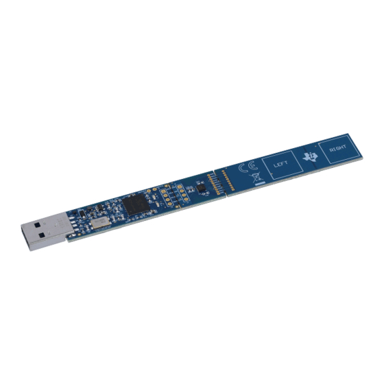
FDC1004EVM User's Guide Introduction The FDC1004EVM evaluation kit is a plug and play system to test and evaluate the FDC1004, 4-Channel capacitive to digital converter. The EVM is a breakable PCB which consists of 3 sections. The first section is a USB to I2C converter based on MSP430F5528 micro-controller, the second section contains the FDC1004 and the third section is a touchless sensor (to demonstrate the sensitivity of the FDC1004) . -
Page 5: Input/Output Connector Description
CIN3 J4.8 CIN4 J4.9 SHLD2 J4.10 J5: 10x1 Header, for the electrical connection between the FDC1004 and the sensor section. SNAU163B – August 2014 – Revised August 2014 FDC1004EVM User's Guide Submit Documentation Feedback Copyright © 2014, Texas Instruments Incorporated... -
Page 6: Hw Setup
FDC1004 is fully managed by the MSP430F5528IRGC microcontroller (U3). The FDC1004 has a fixed I2C address. SW Setup Ensure that the FDC1004EVM GUI and the drivers have been installed on the host computer. Plug the EVM into an available USB port on the host. Operation Plug the EVM into the host computer. -
Page 7: Schematic
Schematic www.ti.com Schematic Figure 4. FDC1004EVM Schematic SNAU163B – August 2014 – Revised August 2014 FDC1004EVM User's Guide Submit Documentation Feedback Copyright © 2014, Texas Instruments Incorporated... -
Page 8: Bill Of Materials
RGC0064B MSP430F5527IPNR Micropower 150 mA Low-Noise Ultra Low-Dropout MF05A_N LP2985AIM5-3.3/NOPB Regulator, 5-pin SOT-23, Pb-Free CRYSTAL 24.000MHZ 18PF SMD ABMM ABMM-24.000MHZ-B2-T FDC1004EVM User's Guide SNAU163B – August 2014 – Revised August 2014 Submit Documentation Feedback Copyright © 2014, Texas Instruments Incorporated... -
Page 9: Revision History
• Added Description of the sensor NOTE: Page numbers for previous revisions may differ from page numbers in the current version. SNAU163B – August 2014 – Revised August 2014 Revision History Submit Documentation Feedback Copyright © 2014, Texas Instruments Incorporated... - Page 10 ADDITIONAL TERMS AND CONDITIONS, WARNINGS, RESTRICTIONS, AND DISCLAIMERS FOR EVALUATION MODULES Texas Instruments Incorporated (TI) markets, sells, and loans all evaluation boards, kits, and/or modules (EVMs) pursuant to, and user expressly acknowledges, represents, and agrees, and takes sole responsibility and risk with respect to, the following: 1.
- Page 11 RADIO FREQUENCY REGULATORY COMPLIANCE INFORMATION FOR EVALUATION MODULES Texas Instruments Incorporated (TI) evaluation boards, kits, and/or modules (EVMs) and/or accompanying hardware that is marketed, sold, or loaned to users may or may not be subject to radio frequency regulations in specific countries.
- Page 12 Les types d'antenne non inclus dans cette liste, ou dont le gain est supérieur au gain maximal indiqué, sont strictement interdits pour l'exploitation de l'émetteur. Mailing Address: Texas Instruments, Post Office Box 655303, Dallas, Texas 75265 Copyright © 2014, Texas Instruments Incorporated spacer Important Notice for Users of EVMs Considered “Radio Frequency Products”...
- Page 13 IMPORTANT NOTICE Texas Instruments Incorporated and its subsidiaries (TI) reserve the right to make corrections, enhancements, improvements and other changes to its semiconductor products and services per JESD46, latest issue, and to discontinue any product or service per JESD48, latest issue.
Need help?
Do you have a question about the FDC1004EVM and is the answer not in the manual?
Questions and answers