Table of Contents
Advertisement
Quick Links
This document is provided with the BOOSTXL-DRV8320RS customer evaluation module (EVM) as a
supplement to the
details the hardware implementation of the EVM and introduces accompanying software.
NOTE: Follow the general ESD precautionary measures when operating this EVM.
...................................................................................................................
1
1.1
1.2
2
2.1
2.2
2.3
2.4
3
3.1
3.2
..................................................................................................................
4
1
2
3
4
5
6
1
2
3
4
5
Trademarks
C2000, Piccolo, InstaSPIN, BoosterPack are trademarks of Texas Instruments.
All other trademarks are the property of their respective owners.
SPRUIJ3A - November 2018 - Revised August 2019
Submit Documentation Feedback
BOOSTXL-DRV8320RS EVM User's Guide
DRV832x 6 to 60-V Three-Phase Smart Gate Driver Data
.............................................................................................................
................................................................................................
.........................................................................................
..................................................................................................
...........................................................................................................
..............................................................................................................
....................................................................................
...................................................................................................
................................................................................................................
..........................................................................................
..................................................................................................................
......................................................................................................
......................................................................................................
...............................................................................................
.......................................................................................................
Copyright © 2018-2019, Texas Instruments Incorporated
SPRUIJ3A - November 2018 - Revised August 2019
Contents
...............................................
List of Figures
List of Tables
............................................................................
............................................................................
............................................................................
............................................................................
BOOSTXL-DRV8320RS EVM User's Guide
User's Guide
Sheet. This user's guide
....................................
2
2
2
3
3
4
7
8
10
10
10
10
2
3
4
5
6
7
8
8
9
9
10
1
Advertisement
Table of Contents

Related Manuals for Texas Instruments BOOSTXL-DRV8320RS


Summary of Contents for Texas Instruments BOOSTXL-DRV8320RS
-
Page 1: Table Of Contents
User's Guide SPRUIJ3A – November 2018 – Revised August 2019 BOOSTXL-DRV8320RS EVM User’s Guide This document is provided with the BOOSTXL-DRV8320RS customer evaluation module (EVM) as a supplement to the DRV832x 6 to 60-V Three-Phase Smart Gate Driver Data Sheet. This user's guide details the hardware implementation of the EVM and introduces accompanying software. -
Page 2: Introduction
The DRV8320RS uses SPI to provide detailed fault reporting and flexible parameter settings such as current control options for slew rate control of the gate drivers and various protection features. BOOSTXL-DRV8320RS has been designed to work with the LAUNCHXL-F280049C LaunchPad. The C2000™ Piccolo™... -
Page 3: Hardware And Software Overview
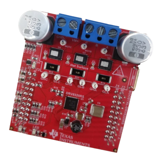
Hardware Connections Overview – DRV8320RS + TMS320F28004xC Figure 2 shows the major blocks of the hardware where the BOOSTXL-DRV8320RS BoosterPack™ plug- in module is mounted on the LAUNCHXL-F280049C LaunchPad development kit. The BOOSTXL- DRV8320RS is designed for an input supply from 6 to 54 V and up to 15-A drive current. Three half h- bridges capable of driving a three-phase BLDC motor using sensorless field oriented or vector control. -
Page 4: Connection Details
A supply voltage ranging from 6 to 54 V from a battery or a DC voltage source is connected to the voltage supply pins. Three phases of the BLDC motor are connected to the three-phase motor socket provided on the BOOSTXL-DRV8320RS. Power... -
Page 5: Jumper Connections 1
A detailed description of each pin's function can be found in Table Figure 4. Jumper Connections 1 SPRUIJ3A – November 2018 – Revised August 2019 BOOSTXL-DRV8320RS EVM User’s Guide Submit Documentation Feedback Copyright © 2018–2019, Texas Instruments Incorporated... -
Page 6: Micro-Usb Connection
F280049C it is important to configure the jumpers as described in Table 5 to avoid shunting separate sources together. Micro-USB Connector Figure 5. Micro-USB Connection BOOSTXL-DRV8320RS EVM User’s Guide SPRUIJ3A – November 2018 – Revised August 2019 Submit Documentation Feedback Copyright © 2018–2019, Texas Instruments Incorporated... -
Page 7: Led Lights
DRV832x 6 to 60-V Three-Phase Smart Gate Driver Data Sheet. The LED marked "LED" is available for the user to control and is active low. SPRUIJ3A – November 2018 – Revised August 2019 BOOSTXL-DRV8320RS EVM User’s Guide Submit Documentation Feedback Copyright © 2018–2019, Texas Instruments Incorporated... -
Page 8: Interfacing Drv8320Rs And Tms320F280049C Launchpad
LAUNCHXL-F280049C, which is mapped appropriately to receive the functionality of the BoosterPack plug-in module. These 40 pins are grouped into 4 ports. Table 1 lists the interfacing of these ports with the TMS320F280049C device. Table 1. J1 BOOSTXL-DRV8320RS Pin Connections BOOSTXL-DRV8320RS LAUNCHXL-F280049 Site1 LAUNCHXL-F280049 Function... -
Page 9: J3 Boostxl-Drv8320Rs Pin Connections
Hardware and Software Overview www.ti.com Table 3. J3 BOOSTXL-DRV8320RS Pin Connections BOOSTXL-DRV8320RS LAUNCHXL-F280049 Site1 LAUNCHXL-F280049 J3 Header Function Function Site2 Function Description — Ground Ground Ground Device Ground Voltage sense A ADCINA5 ADCINA6 Sensing A phase voltage Voltage sense B... -
Page 10: Getting Started
The hardware required to run the motor controller is a LAUNCHXL-F280049C LaunchPad development kit, the BOOSTXL-DRV8320RS BoosterPack plug-in module, a Micro-USB cable, and a power supply with a DC output from 8 to 54 V. Follow these steps to start up the BoosterPack plug-in module: Step 1. - Page 11 NOTE: Page numbers for previous revisions may differ from page numbers in the current version. Changes from Original (November 2018) to A Revision ....................Page ....................• Updates were made in Section 2.2. SPRUIJ3A – November 2018 – Revised August 2019 Revision History Submit Documentation Feedback Copyright © 2018–2019, Texas Instruments Incorporated...
- Page 12 TI products. TI’s provision of these resources does not expand or otherwise alter TI’s applicable warranties or warranty disclaimers for TI products. Mailing Address: Texas Instruments, Post Office Box 655303, Dallas, Texas 75265 Copyright © 2019, Texas Instruments Incorporated...
Need help?
Do you have a question about the BOOSTXL-DRV8320RS and is the answer not in the manual?
Questions and answers