Table of Contents
Advertisement
Advertisement
Table of Contents

Related Manuals for Texas Instruments IWR1443BOOST


Summary of Contents for Texas Instruments IWR1443BOOST
- Page 1 User's Guide SWRU518D – May 2017 – Revised May 2020 IWR1443BOOST Evaluation Module mmWave Sensing Solution SWRU518D – May 2017 – Revised May 2020 IWR1443BOOST Evaluation Module mmWave Sensing Solution Submit Documentation Feedback Copyright © 2017–2020, Texas Instruments Incorporated...
-
Page 2: Table Of Contents
20-Pin Connector Definition (J5) ....................HD Connector Pin Definition ........................Pin Names ......................... SOP Modes ........................ Push Buttons ......................... LEDs IWR1443BOOST Evaluation Module mmWave Sensing Solution SWRU518D – May 2017 – Revised May 2020 Submit Documentation Feedback Copyright © 2017–2020, Texas Instruments Incorporated... -
Page 3: Getting Started
IWR1443 mmWave sensor. For details on getting started with these demos, see mmWave SDK User Guide. BoosterPack, LaunchPad are trademarks of Texas Instruments. ARM is a registered trademark of ARM Limited. Windows is a registered trademark of Microsoft Corporation. -
Page 4: Hardware
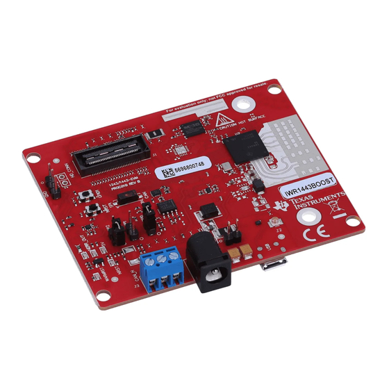
5-V Power 60-Pin HD Connector CAN Connector GPIO1 SW NRST SW SOP Controls Figure 1. EVM Front View IWR1443BOOST Evaluation Module mmWave Sensing Solution SWRU518D – May 2017 – Revised May 2020 Submit Documentation Feedback Copyright © 2017–2020, Texas Instruments Incorporated... -
Page 5: Block Diagram
EN Control 60-Pin from the MCU Copyright © 2017, Texas Instruments Incorporated Figure 3. IWR14xxBOOST Block Diagram SWRU518D – May 2017 – Revised May 2020 IWR1443BOOST Evaluation Module mmWave Sensing Solution Submit Documentation Feedback Copyright © 2017–2020, Texas Instruments Incorporated... -
Page 6: Connecting Boosterpack™ To Launchpad™ Or Mmwave-Devpack
4). This same marking is provided on compatible LaunchPads which must aligned before powering up the boards. Figure 4. 3V3 and 5-V Mark on the LaunchPad™ (White Triangle) IWR1443BOOST Evaluation Module mmWave Sensing Solution SWRU518D – May 2017 – Revised May 2020 Submit Documentation Feedback... -
Page 7: Power Connections
LaunchPads, ensure the pin 1 orientation is correct by matching the 3V3 and 5-V signal marking on the boards (see Figure Figure 6. 20-Pin BoosterPack™ Connectors (J5 and J6) SWRU518D – May 2017 – Revised May 2020 IWR1443BOOST Evaluation Module mmWave Sensing Solution Submit Documentation Feedback Copyright © 2017–2020, Texas Instruments Incorporated... -
Page 8: 20-Pin Connector Definition (J6)
• ANA1/2/3/4 – These are inputs to the GPADCs (general purpose ADC) available on the IWR1443 device. IWR1443BOOST Evaluation Module mmWave Sensing Solution SWRU518D – May 2017 – Revised May 2020 Submit Documentation Feedback Copyright © 2017–2020, Texas Instruments Incorporated... -
Page 9: High Density Connector (60 Pin)
AR_HOSTINTR1 AR_MOSI1 AR_MISO1 PGOOD (onboard VIO) AR_NERR_OUT AR_SYNC_IN AR_LVDS_VALIDP AR_LVDS_VALIDM AR_LVDSSCSI_FRCLKP AR_LVDSSCSI_FRCLKM AR_LVDSSCSI_3P AR_LVDSSCSI_3M AR_LVDSSCSI_2P AR_LVDSSCSI_2M AR_LVDSSCSI_CLKP SWRU518D – May 2017 – Revised May 2020 IWR1443BOOST Evaluation Module mmWave Sensing Solution Submit Documentation Feedback Copyright © 2017–2020, Texas Instruments Incorporated... -
Page 10: Can Connector
0 Ω, and the R4, R6, R28, and R63 resisters must be removed to disconnect the SPI path. Figure 8. CAN Connector IWR1443BOOST Evaluation Module mmWave Sensing Solution SWRU518D – May 2017 – Revised May 2020 Submit Documentation Feedback... -
Page 11: Pc Connection
Mmwave SDK out-of-box demos do not require DevPack. For other labs, check the hardware requirements of the lab user guide. SWRU518D – May 2017 – Revised May 2020 IWR1443BOOST Evaluation Module mmWave Sensing Solution Submit Documentation Feedback Copyright © 2017–2020, Texas Instruments Incorporated... -
Page 12: Antenna
12). Similarly, the horizontal 6dB-beamwidth is approximately ±50 degrees (see Figure and the elevation 6dB-beamwidth is approximately ±20 degrees (see Figure 12). IWR1443BOOST Evaluation Module mmWave Sensing Solution SWRU518D – May 2017 – Revised May 2020 Submit Documentation Feedback Copyright © 2017–2020, Texas Instruments Incorporated... -
Page 13: Antenna Pattern In H-Plane
Hardware www.ti.com Figure 11. Antenna Pattern in H-Plane Figure 12. Antenna Pattern in E-Plane SWRU518D – May 2017 – Revised May 2020 IWR1443BOOST Evaluation Module mmWave Sensing Solution Submit Documentation Feedback Copyright © 2017–2020, Texas Instruments Incorporated... -
Page 14: Jumpers, Switches, And Leds
To measure the current, R118 must be removed and a series ammeter can be put across the P5 pins (see Figure 14). Figure 14. Current Measurement Point IWR1443BOOST Evaluation Module mmWave Sensing Solution SWRU518D – May 2017 – Revised May 2020 Submit Documentation Feedback Copyright © 2017–2020, Texas Instruments Incorporated... -
Page 15: Push Buttons
IWR device. This LED turns on when the Yellow GPIO_1 GPIO is logic-1. SWRU518D – May 2017 – Revised May 2020 IWR1443BOOST Evaluation Module mmWave Sensing Solution Submit Documentation Feedback Copyright © 2017–2020, Texas Instruments Incorporated... -
Page 16: Design Files And Software Tools
EVM kit, along with the screws and nuts help in the vertical mounting of the EVM. Figure 15 shows how the L-brackets can be assembled. Figure 15. Vertical Assembly of the EVM IWR1443BOOST Evaluation Module mmWave Sensing Solution SWRU518D – May 2017 – Revised May 2020 Submit Documentation Feedback Copyright © 2017–2020, Texas Instruments Incorporated... -
Page 17: Pcb Storage And Handling Recommendations
All ESD precautions must be taken while using and handling the EVM. Regulatory Information The IWR1443 evaluation module (IWR1443BOOST) is in compliance with Directive 2014/53/EU. The full text of TI's EU Declaration of Conformity is available here. - Page 18 • Updated Connection With MMWAVE-DEVPACK section....................... • Updated Antenna section......................• Updated PCB Antenna image..........................• Added Note. Revision History SWRU518D – May 2017 – Revised May 2020 Submit Documentation Feedback Copyright © 2017–2020, Texas Instruments Incorporated...
- Page 19 TI products. TI’s provision of these resources does not expand or otherwise alter TI’s applicable warranties or warranty disclaimers for TI products. Mailing Address: Texas Instruments, Post Office Box 655303, Dallas, Texas 75265 Copyright © 2020, Texas Instruments Incorporated...
Need help?
Do you have a question about the IWR1443BOOST and is the answer not in the manual?
Questions and answers