Advertisement
Quick Links
Assembly and operating instructions
Chlorinsitu Wa
EN
A3100
Target group: at least trained and qualified personnel, unless otherwise required.
Please carefully read these operating instructions before use. · Do not discard.
The operator shall be liable for any damage caused by installation or operating errors.
The latest version of the operating instructions are available on our homepage.
Part no. 990575
Original operating instructions (2006/42/EC)
Version:BA CI 035 09/24 EN
Advertisement

Related Manuals for ProMinent Chlorinsitu Wa


Summary of Contents for ProMinent Chlorinsitu Wa
- Page 1 Assembly and operating instructions Chlorinsitu Wa A3100 Target group: at least trained and qualified personnel, unless otherwise required. Please carefully read these operating instructions before use. · Do not discard. The operator shall be liable for any damage caused by installation or operating errors.
- Page 2 Supplemental directives General non-discriminatory approach In order to make it easier to read, this document uses the male form in grammatical structures but with an implied neutral sense. The document is always aimed equally at women, men and gender-neutral persons. We kindly ask readers for their under‐ standing in this simplification of the text.
- Page 3 Table of contents Table of contents Function................5 1.1 System overview............6 1.2 Operating modes............6 1.3 Options................. 7 Safety..................8 2.1 Labelling of Warning Information........8 2.2 User qualification............10 2.3 Safety information............11 2.4 Intended use............... 11 2.5 Sound pressure level..........12 Transport and storage............
- Page 4 Table of contents 6.6 calibrate sensors............42 6.6.1 pH Calibration............42 6.6.2 Chlorine calibration..........45 6.7 Rinse water softener........... 46 During use................48 Maintenance............... 49 8.1 General Maintenance Measures......... 49 Troubleshooting..............51 Disposal of used parts............53 Substances Produced............54 Technical data..............
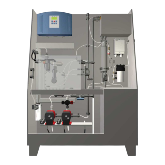
- Page 5 Function Function The Chlorinsitu electrolysis system generates hypochlorous acid from a sodium chloride solution by electrolysis. A3120 Fig. 1: Chlorinsitu electrolysis system Unit identification Tab. 2: Unit identification Unit type Order no. 1115512 1115524 Scope of delivery Chlorine electrolysis system Integrated salt-dissolving tank Injector (optional) Booster pump (optional)
- Page 6 Function 1.1 System overview A3121 Fig. 2: System overview Control unit Outlet, hypochlorous acid Brine pump Outlet, hydrogen Alkali pump 10 Inlet, swimming pool water Reverse osmosis 11 Inlet, drinking water Membrane cell 12 Tank for softened water Float 13 Brine tank Plunger 14 Drain (waste water) 1.2 Operating modes...
- Page 7 Function On / Off "I" You adjust the system, as with "M" manual mode, to the required volume of chlorine. An external potential-free control contact of a chlorine and pH controller is used to switch the system on and off. Pulse signal "F"...
- Page 8 Safety Safety 2.1 Labelling of Warning Information Introduction These operating instructions provide information on the technical data and functions of the product. These operating instructions pro‐ vide detailed warning information and are provided as clear step- by-step instructions. The warning information and notes are categorised according to the following scheme.
- Page 9 Safety Type of information Hints on use and additional information. Source of the information. Additional measures. Denotes hints on use and other useful informa‐ – tion. It does not indicate a hazardous or dam‐ aging situation.
- Page 10 Safety 2.2 User qualification WARNING! Danger of injury with inadequately qualified per‐ sonnel The operator of the system / equipment is respon‐ sible for ensuring that the qualifications are ful‐ filled. If inadequately qualified personnel work on the unit or loiter in the hazard zone of the unit, this could result in dangers that could cause serious injuries and material damage.
- Page 11 Safety 2.3 Safety information WARNING! Danger from hazardous substances! Possible consequence: Fatal or very serious inju‐ ries. Please ensure when handling hazardous sub‐ stances that you have read the latest safety data sheets provided by the manufacture of the haz‐ ardous substance.
- Page 12 Safety 2.5 Sound pressure level The sound pressure level is < 70 dB (A) at maximum power (without an additional pump).
- Page 13 Transport and storage Transport and storage User qualification, transport and storage: trained user Ä Chapter 2.2 ‘User qualification’ on page 10 Transport The system is packaged and shipped with all components on a single pallet. The system does not contain any chemicals or water when shipped.
- Page 14 Assembly and installation Assembly and installation User qualification, installation: trained and qualified personnel Ä Chapter 2.2 ‘User qualification’ on page 10 User qualification, hydraulic installation: trained and qualified Ä Chapter 2.2 ‘User qualification’ on page 10 personnel User qualification, electrical installation: electrical technician Ä...
- Page 15 Assembly and installation III. A3125 Fig. 3: The figure shows the hydraulic connectors. Swimming pool water, inlet II. Hypochlorous acid, outlet III. Drain IV. Drain V. Hydrogen gas, outlet VI. Drinking water, inlet Route the hydrogen drainage line uniformly upwards to the outside with the EX-label supplied on the outside of the pipe.
- Page 16 Assembly and installation 4.2.2 Brine tank The brine tank is integrated in the system and is supplied ready-connected. Check the leak-tightness of the connectors during commissioning and after 1 week. 4.3 Installation, electrical Refer to the wiring diagram for all electrical connections as well. We recommend connecting the system to a separate power circuit fused with 16 A (minimum 6 A).
- Page 17 Assembly and installation 4.3.1 System wiring diagram DIAPHRAGM CELL ERROR CONTACTS STATUS CONTACTS CONTACT FROM FILTER FLOW CONTACT FROM FLOW SWITCH IN DEVICE CONTACT FROM BRINE LEVEL METERING PUMPS EXTERNAL CONNECTOR VALVE BRINE TANK FILL VALVE BRINE PRIMING/ REGENERATE VALVE TO WASTE WATER VALVE REFRESH ALKALI/LYE...
- Page 18 Assembly and installation 4.3.2 External connector terminals 24 V + 4-20mA - 4-20mA Pulse + 4-20mA 24 V 24 V + 4-20mA Pulse - 4-20mA + 4-20mA 24 V P_PMA_EL_0029_SW_2 Fig. 5: External connector terminals A 4 ... 20 mA active signal B 4 ...
- Page 19 Assembly and installation 4.3.6 Flow switch for the bypass fittings An internal flow contact (reed switch), which internally monitors the [FLOW] terminals of the control unit. An flow, is connected to the external flow contact of a bypass fitting can thus be connected in series.
- Page 20 Set up Set up 5.1 General Operating menu, diagrammatical Info-level Input (with sensor) ENABLE: STANDBY ACTIVE - M- ACTIVE - M- ACTIVE - M- ACTIVE - R- Chlorine requirement: Lye requirement: Acid requirement: 100.0% 10.0% 10.0% 0.45 14:22 4.16V 22.3A 14:22 STOP START USER S...
- Page 21 Set up Access codes The menus are protected using access codes with the following levels: Name Enables ... Access code ‘User’ Enables functions which trained per‐ sonnel must use in their day-to-day work. ‘Installer’ For basic settings during start up and Only known by suitably trained per‐...
- Page 22 Set up SETTING level Settings - general approach To set or adjust something, the system must first be stopped and the password available: [START/STOP] . Press USER S Press Stop Fig. 8: Display. [OK] for example if you wish to enter a setting in the Press USER ‘User’...
- Page 23 Set up CHOICE Password User User CHOICE Password Mechanic Calibration CHOICE Password User Mechanic (only with sensors) CHOICE Password User Sensor calibr. CHOICE Password User Startup CHOICE Password Mechanic Test CHOICE RINSE Password User Remaining: 600 s Rinse CHOICE REGENERATI Password Remaining: 2000 s User...
- Page 24 Set up Functions of the keys Key on the Display in the text Functions system Change between the continuous displays and the menus Continue without saving [START/STOP] Stop/Start [OK] Save and / or next [DOWN] Change the value or selection in the menu [ESC] Back to the ‘Selection menu’...
- Page 25 Set up 5.3 mA Calibration Menu This menu is used to calibrate the 4 ... 20 mA inputs - only for trained Service personnel or by consultation with the supplier. The menu is only available in English. ‘Installer’ password is required. [OK] to reset the existing values.
- Page 26 Set up 5.4 Installer Menu This menu is intended solely for authorised personnel. [OK] to access the menu. Press CHOICE CHOICE Manufacturer [DOWN] key to set the password. Use the MANUFACTURER MANUFACTURER Password [OK] and then [S] . Press MANUFACTURER MANUFACTURER This is where the duration is set for which the brine pump primes brine during regeneration of the water softener.
- Page 27 Set up Press [OK] and then [S] . MANUFACTURER MANUFACTURER This is where the duration that the solenoid valve SL remains open per pulse to fill the cathode is set. Cath. pulslength [arrow keys] ). Set the desired value ( mSec [OK] and then [S] .
- Page 28 Set up Language setting The text in the ‘Test’ menu is in English, inde‐ pendently of the language setting. [FSB] to fill the brine storage tank. To Test the solenoid valve TEST MODE [OK] to switch between [open] and [closed] . do so, use ð...
- Page 29 Set up Check the [ON] or [OFF] status of the alarm relay [ERROR] . TEST MODE Use the arrow keys to move to the next parameter. Relay error A2334 Fig. 19: Status of the relay [ON] or [OFF] status of the status relay [STATUS] . Check the TEST MODE Use the arrow keys to move to the next parameter.
- Page 30 Set up Check the number of pulses per minute of chlorine require‐ TEST MODE [CI Pulse] . ment Use the arrow keys to move to the next parameter. Cl Pulse A2340 Fig. 25: Number of pulses per minute [ON] or [OFF] status of alkali metering Check the TEST MODE [Lye metering] .
- Page 31 Set up In the main ‘Selection’ menu, select the ‘Rinse’ menu RINSE [arrow keys] ) and press [OK] . Remaining ‘Remaining time’ has elapsed, the control jumps to the Once the ‘USER S’ . central menu item 5.9 Regenerate Menu This menu is used for the manual regeneration of the water soft‐...
- Page 32 Start up Start up We would recommend that the supplier starts up the system to ensure its subsequent trouble-free operation. The following steps are necessary: 1 - Batch brine 2 - Check prerequisites 3 - Only with initial commissioning: run through the ‘SETUP’...
- Page 33 Start up 6.1.1 Requirements relating to the starting substances Salt Preferably use vacuum salt. It should be of food-quality for human use. Use salt with as few impurities as possible to ensure a long service life for the diaphragm cell. Use regeneration salt with: Minimum grain size 0.38 mm...
- Page 34 Start up Check point Water pressure downstream of the reducing valve is approx. 1.7 bar. Hydrogen discharge line is routed to the outside and an Ex-sticker has been adhered. Room ventilation is acceptable. Drainage line to the sewer system is sufficiently large and has a sufficient drop. Water hardness upstream and downstream of the water softener.
- Page 35 Start up While the pump is running, vent the suction line. To do this, unscrew the vent valve anticlockwise. Once it has been vented, screw the vent valve tightly closed again clockwise. Fig. 31: Pump vent valve Now check whether the pump on the anode side of the mem‐ brane cell has completely filled the hose to the membrane cell and that liquid and bubbles can be seen at the outlet of the anode side (1).
- Page 36 Start up Check whether the hoses from and to the cathode side (3) of the membrane cell have filled completely. This takes approx. 5 seconds. If fitted, then the water level must be visible in the alkali tank. If fitted, then vent the alkali pump and the suction hose, as you did with the brine pump.
- Page 37 Start up Using the [DOWN] key, set "999" and press [OK] . USER [S] . Press Password [arrow keys] and If necessary, set the language using the USER press [OK] . Language German [S] . Press USER Cl input signal Manual ‘User’...
- Page 38 Start up Press [OK] and then [S] . USER The display indicates the alkali production set, based on the maximum possible alkali production. Lye manual [arrow keys] ) and press [OK] . Enter the required value ( 50 % [S] . Press 6.4.2 On / Off Operating Mode ("I") [S] .
- Page 39 Start up Press [S] . USER pH (Lye) signal Pulse Press [OK] and then [S] . USER The display indicates the pulse frequency for the maximum alkali demand. pH pulse @ 100 % [arrow keys] ) and press [OK] . Enter the required value ( pulse [S] .
- Page 40 Start up Press [S] . USER Set the required P-band (proportional band) for the setpoint [arrow keys] and press [OK] . for the chlorine control using the Cl sensor P-Band 0.30 ppm With a setpoint of 1.00 ppm and a P-band of 0.30 ppm, chlorine metering is maximum with a measured value of 0.70 ppm.
- Page 41 Start up Press [OK] and then [S] . USER [arrow keys] to set the hours of the current time and Use the [OK] . press Clock Time Hours Hour [S] . Press USER [arrow keys] to set the minutes of the current time Use the [OK] .
- Page 42 Start up Press [S] . ACTIVE The measured chlorine concentration is 0.40 ppm. The measured pH value is 7.1. Chlorine: 0.40 If fitted: Calibrate the chlorine and pH sensors. 6.6 calibrate sensors [Start / Stop] key. Stop the system with the USER S Press START [S] .
- Page 43 Start up 6.6.1.1 2-point calibration SELECTION MENU SENSOR pH sensor cal. Sensor calibr. SENSOR Two-point cal. SENSOR pH buffer 1 (4) SENSOR Wait time! ***** SENSOR pH buffer 2 (10) SENSOR Wait time ***** SENSOR SENSOR SENSOR pH sensor pH sensor pH sensor good acceptable...
- Page 44 Start up Immerse the pH sensor in quality buffer 1 = pH 4, stir with the SENSORS SENSORS [OK] . pH sensor and press Hold the pH sensor in the quality buffer, without touching the Wait time! wall of the storage tank until this display appears: ************** SENSORS SENSORS...
- Page 45 Start up 6.6.2 Chlorine calibration CHOICE SENSOR SENSOR pH sensor cal. Chlorine sensor cal. Sensor calibr. SENSOR Actual value SENSOR SENSOR SENSOR Chlorine sensor Chlorine sensor Chlorine sensor False good satisf. SENSOR Chlorine sensor Re-calibrate? B0449 [Start / Stop] key. Stop the system with the USER S Press START...
- Page 46 Start up NOTICE! – Also note the operating instructions for the chlorine sensor and the bypass fitting. – Slope calibration has to be re-calibrated at reg‐ ular intervals to ensure perfect operation of the chlorine sensor. It is enough to calibrate the sensor every 3 ... 4 weeks with swimming pools or potable water.
- Page 47 Start up Fig. 34: The sampling unit in the brine storage tank Loosen the blue hose (1) from the sampling unit and route it into a bucket. Then pull the grey cap (2) off the sampling unit and raised the level switch out of the brine. ð...
- Page 48 During use During use Inspect the system daily, see the "Maintenance" chapter. CAUTION! The membrane cell can be damaged irreparably. Top up only with salt (NaCl) that conforms to the specifications - see chapter "Start up".
- Page 49 Maintenance Maintenance 8.1 General Maintenance Measures Standard maintenance kits Maintenance by your supplier is necessary once a year to ensure that the system operates perfectly. In this, a distinction is made between annual and three-year maintenance. Standard maintenance kits are available. Rinsing the system internally Before working on the system, rinse the system internally to free it from chemicals.
- Page 50 Maintenance Interval Maintenance work If the system stops working, check whether it is a normal control stop or if whether there is ‘Standby’ ). no external enable condition ( If an unusual situation occurs, check the system again after a short while. If the situation persists, inform the supplier.
- Page 51 Troubleshooting Troubleshooting WARNING! Chlorine, sodium hydroxide solution, hydrogen and sodium hypochlorite can be released from the system. Pay attention to this! WARNING! Only allow the work described to be performed by authorised personnel. Errors without error messages Fault description Cause Remedy LCD screen is dark (no Fuse defective...
- Page 52 Troubleshooting Errors with error messages Fault description Cause Remedy ‘Not active’ [ENABLE] contact. No enable - the system is on Check the external standby ‘Brine level low’ Liquid level switch Check the liquid level switch in the brine storage tank. Leaks Check the hoses.
- Page 53 Refer to the Material Safety Data Sheet for your feed chemical. A current Declaration of Decontamination is available to download on the ProMinent website. Sign indicating EU collection system In accordance with the European Directive 2012/19/EU on waste electrical and electronic equipment, this device features the symbol showing a waste bin with a line through it.
- Page 54 Substances Produced Substances Produced WARNING! Danger from hazardous substances! Possible consequence: Fatal or very serious inju‐ ries. Please ensure when handling hazardous sub‐ stances that you have read the latest safety data sheets provided by the manufacture of the haz‐ ardous substance.
- Page 55 Substances Produced Tab. 8: Hydrogen Property Unit Value ICSC / CAS 0001 / 133-74-0 H-statements H220, P210 Boiling point °C -253 Flash point Flammable gas Ignition temperature °C Temperature class Relative density relative to air 0.07 Absolute density kg/m³ 0.08908 Molar mass g/mol Explosive limits (LEL - UEL)
- Page 56 Technical data Technical data parameters Type 25 Type 50 Output [g/h] Mains voltage [VAC] 230± 5% 230 ± 5% Mains frequency [Hz] Power consumption [kW] 0.11 0.22 Control fuse [A] Mains power line fuse [A] Contact guard, with fitted hood IP42 IP42 Salt consumption [g/h]...
- Page 57 Technical data Ambient conditions Specification Value Minimum ambient temperature + 10 °C Maximum ambient temperature + 35 °C Max. air humidity, non-condensing 85% relative air humidity Miscellaneous: Protect against sunlight Sound pressure level The sound pressure level is < 70 dB (A) at maximum power (without the booster pump).
- Page 58 EC directives: Tab. 12: Extract from the EC Declaration of Conformity Designation of the product: Chlorinsitu TopElec or Compact V2.0 or Chlorinsitu Wa Serial number: see nameplate on the unit Relevant EC Directives: EC Machinery Directive (2006/42/EC) EU EMC Directive (2014/30/EU) Compliance with the protection targets of the Low Voltage Directive 2014/35/EU according to Appendix I, No.
- Page 59 Index Index 1, 2, 3 ... 2-point calibration ......43 INFO level ......21 4 ...
- Page 60 Index Rinsing ....... . 30 Salt, requirements ......33 Selection menu .
- Page 64 Glashorst 114 3925 BV Scherpenzeel Netherlands Telephone: +31 (0)33-2778600 Fax: +31 (0)33-2778399 Internet: www.vdhwater.nl Email: info@vdhwater.nl 990408, 1, en_GB ProMinent GmbH Im Schuhmachergewann 5-11 69123 Heidelberg Germany Telephone: +49 6221 842-0 Fax: +49 6221 842-215 Email: info@prominent.com Internet: www.prominent.com © 2022...
Need help?
Do you have a question about the Chlorinsitu Wa and is the answer not in the manual?
Questions and answers