Table of Contents
Advertisement
Quick Links
Assembly and operating instructions
DULCO
turb C Measuring Device for Tur‐
®
bidity
Types: TUC 1, TUC 2, TUC 3, TUC 4
EN
Please carefully read these operating instructions before use. · Do not discard.
The operator shall be liable for any damage caused by installation or operating errors.
The latest version of the operating instructions are available on our homepage.
Mahar Fan
Mahar Fan
Part no. 986062
BA DT 053 08/16 EN
Advertisement
Table of Contents

Related Manuals for ProMinent DULCO TUC 1


Summary of Contents for ProMinent DULCO TUC 1
- Page 1 Assembly and operating instructions DULCO turb C Measuring Device for Tur‐ ® bidity Types: TUC 1, TUC 2, TUC 3, TUC 4 Please carefully read these operating instructions before use. · Do not discard. The operator shall be liable for any damage caused by installation or operating errors. The latest version of the operating instructions are available on our homepage.
- Page 2 Supplemental instructions General non-discriminatory approach In order to make it easier to read, this document uses the male form in grammat‐ ical structures but with an implied neutral sense. It is aimed equally at both men and women. We kindly ask female readers for their understanding in this simplification of the text.
- Page 3 Supplemental instructions Symbol Description ‘Display /GUI’ Screen elements (e.g. buttons, assignment of function keys). Presentation of software elements and/or texts. CODE Mahar Fan Mahar Fan...
-
Page 4: Table Of Contents
Table of contents Table of contents Introduction......................6 1.1 Labelling of Warning Information..............6 1.2 Users' qualifications..................8 Safety and responsibility..................10 2.1 General safety information ................10 2.2 Correct and proper use................11 Functional description / product identification............12 3.1 Scope of delivery.................. - Page 5 Table of contents 8.1.2 Faults in the process................. 69 Spare parts and accessories................71 Disposal of Used Parts..................72 Declaration of Conformity..................73 Index........................74 Mahar Fan Mahar Fan...
-
Page 6: Introduction
Introduction Introduction Data and functions These operating instructions describe the WARNING! technical data and functions of the Nature and source of the danger DULCO turb C Measuring Device for ® Possible consequence: Fatal or very Turbidity. serious injuries. Measure to be taken to avoid this Labelling of Warning Infor‐... - Page 7 Introduction NOTICE! Nature and source of the danger Damage to the product or its sur‐ roundings. Measure to be taken to avoid this danger. – Denotes a possibly damaging sit‐ uation. If the situation is disre‐ garded, the product or an object in its vicinity could be damaged.
-
Page 8: Users' Qualifications
Trained user A trained user is a person who fulfils the requirements made of an instructed person and who has also received additional training specific to the system from ProMinent or another authorised distribution partner. Trained qualified per‐ A qualified employee is deemed to be a person who is able to sonnel assess the tasks assigned to him and recognize possible haz‐... - Page 9 Customer Service department refers to service technicians, department who have received proven training and have been authorised by ProMinent to work on the system. Note for the system operator The pertinent accident prevention regulations, as well as all other generally acknowl‐...
-
Page 10: Safety And Responsibility
Safety and responsibility Safety and responsibility General safety information WARNING! Operating errors! WARNING! Possible consequence: Fatal or very Live parts! serious injuries. Possible consequence: Fatal or very – The unit should only be operated serious injuries by adequately qualified and tech‐ –... -
Page 11: Correct And Proper Use
Safety and responsibility Correct and proper use NOTICE! Correct and proper use NOTICE! Damage to the product or its sur‐ Correct and proper use roundings The device is designed to measure – The unit is not intended to the turbidity of water. measure or regulate gaseous or The unit may only be used in accord‐... -
Page 12: Functional Description / Product Identification
Functional description / product identification Functional description / product identification Brief description of the function The DULCO ® turb C has been developed for the online measurement of turbid matter in untreated water, process water and treated process water in drinking water abstraction. The DULCO turb C product line consists of four types of device: ®... - Page 13 Functional description / product identification Specifications Measuring range 0 – 1000.0 NTU Accuracy limit ± 2% of the displayed value or ± 0.02 NTU under 40 NTU, depending on which value is the greater. ± 5% of the displayed value above 40 NTU Resolution 0.0001 NTU below 10 NTU Response time...
- Page 14 Functional description / product identification Dimensions: Space requirements: 35 cm x 30 cm x 30 cm (height/width/depth) Shipping weight approx. 2.5 kg Optional: ultrasonic cleaning (TUC 3 / Interface RS-485 TUC 4) The DULCO turb C is able to offer basic ®...
-
Page 15: Scope Of Delivery
C from the packaging box. Carefully check the components. Ensure that no visible damage has been caused during shipping. If the components sup‐ plied fail to comply with the order, please contact your local distributor or the ProMinent customer services department immediately. -
Page 16: Assembly And Installation
Assembly and Installation Assembly and Installation Read-off and operating position NOTICE! Install the device in a position Drying agent – where it can be read and oper‐ Possible malfunctioning of ated easily (at eye level if pos‐ DULCO ® turb C due to moisture in the sible) device. -
Page 17: Wall-Mounting
Assembly and Installation Wall-mounting Installation (mechanical) NOTICE! Distance to the sampling site Install the DULCO ® turb C no further than 3 metres away from the sampling site. This is the only way to ensure a quick response time from the system. Free space above the sensor Leave at least 200 mm clearance above the DULCO turb C for carrying out any... - Page 18 Assembly and Installation A0515 Fig. 1: The diagram is not to scale. It is for information only. All values given in millime‐ tres. Terminal box DULCO turb C housing ® Mahar Fan Mahar Fan...
- Page 19 Assembly and Installation Fig. 2: The diagram is not to scale. It is for information only. All values given in millime‐ tres. Terminal box DULCO ® turb C housing Fasten the terminal box (A) to the wall with two M4 screws Fasten the DULCO turb C housing (B) to the wall above the terminal box using ®...
-
Page 20: Installation (Hydraulic)
Assembly and Installation Installation (hydraulic) Permissible operating parame‐ ters CAUTION! Maximum liquid temperature 50 – Free flow at outlet °C Direct any sample water that has Maximum pressure 13.8 bar – flowed through the DULCO turb C ® Flow rate 6 ... 60 l/h –... - Page 21 Assembly and Installation Fig. 3: Recommended cabling for the DULCO turb C ® Flow unit Vent screw. For use on pressurised Sensor unit with operating unit systems. Not used for pressureless III. Terminal box systems Back pressure valve. To regulate the Hose connector.
-
Page 22: Installation (Electrical)
Assembly and Installation Hose connector. 4.75 mm interior Detail: Union nut hose connection diameter, 8 mm external diameter. Detail: Replacement hose connection Hose connection to the sampling site Shut-off clamp. To shut-off the inlet in Detail: Hose an emergency or for necessary work Installation (electrical) WARNING! Live parts! - Page 23 Assembly and Installation RS-485 The RS-485 digital interface (2 leads / half duplex) is characterised by a very high tolerance to electromagnetic interference due to the symmetrical signal transmission. This means that cable lengths of up to 900m can be used. The final device on a bus must be equipped with a 120 ohm resistor, in order to avoid signal overlapping.
- Page 24 Assembly and Installation A0518 Fig. 4: Cable assignment for DULCO turb C ® Sensor cable Terminal box Liquid-tight threaded connection Mahar Fan Mahar Fan...
- Page 25 Assembly and Installation A0646 Fig. 5: Cable assignment at DULCO turb C terminal box ® Power cable threaded connection Terminal 4-20 mA / RS 485 (0.25 - 1.5 (supplied without power cable) Alarm cable threaded connection Terminal box III. Sensor cable threaded connection Terminal power cable (0.25 - 1.5 mm Terminal Alarm 1 and 2 (0.25 - 1.5 ) maximum 2 A...
- Page 26 Assembly and Installation All terminals in the terminal box are labelled and are self-explanatory. All cable bushings are equipped with blanks on shipping. These must be removed as required. Strip the Insulation on all cables to a length of 6 mm. Equip all cables with strain relief.
-
Page 27: Operating Diagram
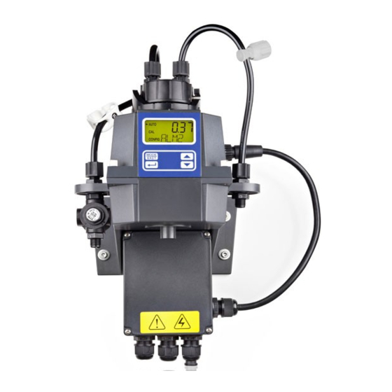
Operating diagram Operating diagram Overview of device /Control elements Ä Chapter 1.2 ‘Users' qualifications’ Users' qualification: Instructed person, see on page 8 Fig. 6: Overview of device /Control elements LCD display UP key DOWN key ENTER button MODE/EXIT button Function Description LCD display The parameters of the respective mode are shown on the LCD... -
Page 28: Overview Of Operating Structure
Operating diagram Function Description DOWN key To decrease a displayed number ENTER button To apply, confirm or save a displayed value or status or [CAL] , MODE/EXIT button In order to call-up and select the three optional modes [CONFIG] and [AUTO] (measurement) Overview of operating struc‐... - Page 29 Operating diagram Fig. 7: Overview of operating structure Mahar Fan Mahar Fan...
- Page 30 Operating diagram Configuration menu The configuration menu is subdivided into several submenus, in order to facilitate configuration. The following submenus are available: [O/P] Select the output Configuration of 4 ... 20 mA interface [ERLV] Configuration of the alarm [ALM1 / ALM2] [OFST] Configuration of the offset Configuration of access protection...
-
Page 31: Commissioning
Commissioning Commissioning Unit NTU (optionally FNU) The NTU (Nephelometric Turbidity Unit) is a unit used for measuring turbidity in liquids. Alternatively, the measured value may be displayed in FNU (Formazine Nephelometric Ä ‘Units’ on page 48 . The calculation is undertaken 1:1. Unit), see Measured values above 1000 NTU fall outside the measuring range of this DULCO ®... -
Page 32: Inserting The Drying Agent
[DESC] (for [Desiccant] = drying agent). the lower row of the LCD display; Warning Replacement drying agent bags can be obtained from Prominent or from your local rep‐ resentative. Saturated drying agent can cause an alarm to be triggered, in order to indicate the Ä... - Page 33 Commissioning Fig. 9: Inserting the drying agent Insert the drying agent immediately after opening the packaging, in order to avoid premature saturation. Remove the new drying agent bag (2) from the packaging and place it together with the humidity indicator card (3) in the lower part of the DULCO ®...
- Page 34 Commissioning ð The DULCO turb C must be reset in order to enable detection of the new ® drying agent. To do this, remove the sensor connection cable for 2 seconds from the DULCO ® turb C and then reconnect it. Otherwise, the warning [DESC] may appear on the LCD display.
-
Page 35: Routine Measurement
Commissioning Always use the original packaging. If you do not have any of the original drying agent, use 113 ... 170 grammes zeolite-based drying agent (molecular sieve) of similar quality (3 Å pore width). Silica gel and other chemical drying agents may not be used. Routine measurement Routine measurement: The turbidity can be correctly measured approx. -
Page 36: Access Code
Commissioning Access code The access code cannot be changed. You can activate the access code for the DULCO turb C in the configuration menu. If ® ‘Key’ symbol (1) is shown in the lower right-hand the access code has been activated, a [MODE/EXIT] button is operated. -
Page 37: Device Configuration
Commissioning ð If you have selected the valid access code, you will now have access to the DULCO ® turb C's calibration mode. If the access code is incorrect, the DULCO ® turb C returns to AUTO mode. Device configuration 6.4.1 Selecting the output A0530... - Page 38 Commissioning Function Options Info Value 20 mA 0 ... 1000 NTU Selection of the upper tur‐ bidity limit value (UPLM)✱✱, which corre‐ sponds to the output value 20 mA. ‘value 20 mA’ , in order to reverse the ✱ = a higher NTU value can be entered than for sign of the output current ‘value 4 mA’...
-
Page 39: Configuration Of Fault Current (Erlv)
Commissioning 6.4.2 Configuration of fault current (ERLV) A0625 Fig. 13: Configuration of fault current (ERLV) The 4-20 mA signal output can be utilized in the event of a system error on the DULCO ® [ERLV ON] function. In doing so, turb C in order to indicate the problem by activating the fault currents of 4.00 mA, 2.00 mA or 0 mA can be selected. -
Page 40: Configure Alarm
Commissioning 6.4.3 Configure alarm Limit value alarm The turbidity threshold at which the alarm The DULCO ® turb C is equipped with two ‘Limit is triggered is referred to as the independently programmable alarm value alarm’ . You can configure the limit relays. - Page 41 Commissioning Menu Alarm A0531 Fig. 14: Menu Alarm Operation Options Info Alarm 1 (ALM1) Select the alarm function Alarm 2 (ALM2) ERROR ‘Limit value alarm’ Limit value (S/P) 0 ... 1000 NTU Set the Delay time alarm on 1 ... 30 s Set the number of seconds ‘Delay alarm on’...
-
Page 42: Offset Configuration
Commissioning 6.4.4 OFFSET configuration The OFFSET symbol is shows as soon as an offset is being used. The maximum offset amounts to 1.00 NTU. If the device deviation is greater than 1 NTU, then it is recommended to carry out a complete calibration. A0624 Fig. - Page 43 Commissioning In certain circumstances it may be desirable to use an offset function in order to balance Ä Chapter the device, instead of performing a complete calibration (as described under 7.1 ‘Calibrating DULCO turb C’ on page 55 ). This procedure is not recommended as a ®...
-
Page 44: Extended Settings
Commissioning At this point, the offset configuration is completed. At this stage, the device [CONFIG] . Press the key [MODE/EXIT button] in remains in configuration mode [AUTO] order to return to 6.4.5 Extended settings Extended settings A0532 Fig. 16: Extended settings Mahar Fan Mahar Fan... - Page 45 Commissioning Function Options Info [ON] (On) Extended settings Select the function "Extended settings" in [OFF] (Off) order to access configura‐ tion for the following options: Speed of response Screen resolution LCD illumination bright‐ ness Units Ultrasonic cleaning RS-485 parameters Alarm drying agent Response time A0533 Fig.
- Page 46 Commissioning Function Options Info Reaction time 1 ... 100 % Select a reaction time for the displayed (RESP) and output NTU values. Factory setting: 10 % Select the highest reaction time (i.e. the highest number) in order to avoid anoma‐ lies caused by air or other influences.
- Page 47 Commissioning Function Options Info Screen resolution (RES) 1 ... 0.001 For displayed values under 10 NTU the Factory setting: 0,01 DULCO ® turb C is able to display a value with up to four digits after the decimal point LCD illumination brightness A0535 Fig.
- Page 48 Commissioning Units A0536 Fig. 20: Units Function Options Info Units (UNIT) Select a unit for displaying the turbidity measurement: Factory setting: NTU [Nephelometric Turbidity Units] [Formazin Nephelometric Units] Mahar Fan Mahar Fan...
- Page 49 Commissioning Ultrasonic cleaning (models TUC 3 and TUC 4) Error message in the event of incorrect cuvette Only active if a corresponding cuvette with ultrasound transducer is used. If you use a cuvette without an ultrasound transducer, then an error message will be shown on the LCD display.
- Page 50 Commissioning RS-485 parameters A0538 Fig. 22: RS-485 parameters Function Options Info Bits (BITS) The required number of data bits for the communi‐ cations software deployed Factory setting: 8 Parity (PRTY) nOnE The parity bit required for the communications soft‐ ware. Factory setting: nOnE Stop The stop bit required for the...
- Page 51 Commissioning Drying agent alarm A0539 Fig. 23: Drying agent alarm Function Options Info [ON] (On) [ON,] in order to Drying agent alarm (DESC) Select trigger an alarm when the [OFF] (Off) drying agent is saturated [OFF] Factory setting: ‘ERROR’ , see In order to activate one or both alarms, then you must configure Ä...
- Page 52 Commissioning A0607 Fig. 24: Configuration of 4 mA output Function Options Info Configuration of 4 mA - 40 ... + 40 Configure the mA value in output order to adapt to the super‐ ordinated control system (e.g. SPC or SCADA) One count number corre‐...
- Page 53 Commissioning A0608 Fig. 25: Configuration of 20 mA output Function Options Info Configuration of 20 mA - 1000 ... + 1000 Configure the mA value in output order to adapt to the super‐ ordinated control system (e.g. SPC or SCADA) One count number corre‐...
- Page 54 Commissioning You can access the configuration menu at any time in order to reset or modify some or all of the parameters. You can exit the configuration menu at any time by [MODE/EXIT button] . In pressing the doing so, any changes to the parameters that you have modified will be stored.
-
Page 55: Operation
If possible, use a standard solution If the DULCO turb C is in [CAL] or ® from Prominent for calibration. These [CONFIG] mode, the alarm relay standard solutions are more stable changes to alarm status. If no input is than formazine and have a minimum made in [CAL]mode within a period of shelf-life of 12 months. - Page 56 Operation Indexing the standard solution with your cuvette CAUTION! Malfunction of the control circuit Possible consequence: Poor end-product quality Ensure that your controller or other measuring equipment is configured so that the indexing process does not lead to unintentional control functions in the measuring and control system.
- Page 57 Operation A0647 Fig. 26: Insert sheet for standard solutions Handling the standard solution The standard solution 1000 NTU must be lightly shaken before use for calibration. Standard solution 10 NTU must be transferred to the cuvette from the storage bottle before it is used for the first time.
- Page 58 Operation Transfer 10 NTU standard solution into the cuvette A0649 Fig. 27: Labels on the storage bottle 10 NTU Rinse a cuvette using 5 ml of 10 NTU standard solution. ð Dispose of the 5 ml rinsing solution afterwards. Fill the rinsed cuvette with 20 ml 10 NTU standard solution. Clean and dry the exterior of the cuvette, before inserting the cuvette into the DULCO ®...
- Page 59 Operation Purpose of indexing The standard solution cuvettes have a minimal manufacturing tolerance. This manu‐ facturing tolerance results from the manufacturing process and is unavoidable. In order to minimise the effects of these manufacturing tolerances on the calibration process, you must index and mark the position on the cuvette with the lowest tur‐ bidity value (lowest NTU value).
- Page 60 Operation [AUTO] mode. Prerequisite: The DULCO turb C is ready for operation and is set to ® Open the flow unit by screwing it clockwise and remove the in-line flow fitting from the cuvette. [1000 NTU] calibration cuvette into the DULCO Insert the turb C.
-
Page 61: Perform Calibration
Operation 7.1.2 Perform calibration CAUTION! Malfunction of the control circuit Possible consequence: Poor end-product quality Ensure that your controller or other measuring equipment is configured so that the calibration process does not lead to unintentional control functions in the measure‐ ment and control system. - Page 62 Operation [AUTO] mode. Prerequisite: The DULCO turb C is ready for operation and is set to ® Fig. 28: Display [Calibration 1000 NTU] [CAL] mode by pressing the [MODE/EXIT] key once Select [CAL] entry in the LCD display (see Fig. 28). The ð...
- Page 63 Operation A0523 Fig. 29: Display [Start calibration ] [1000 NTU] Press the ↲ key to start calibrating at ð A 30 second countdown begins, after which the DULCO turb C is calibrated ® [1000 NTU] . A0525 Fig. 30: Display [Calibration 10 NTU] [1000 NTU] calibration cuvette Remove the Mahar Fan...
- Page 64 Operation [10 NTU] calibration cuvette into the DULCO Insert the turb C so that the marker ® Ä ‘Indexing the standard solution with your cuvette’ is facing towards you, see on page 56 Slowly rotate the calibration cuvette 20° from the centre point to the left and then 20°...
- Page 65 Operation A0526 Fig. 32: Display [Calibration 0.02 NTU] [10 NTU] calibration cuvette Remove the [0.02 NTU] calibration cuvette into the DULCO Insert the ® turb C so that the Ä ‘Indexing the standard solution with your cuvette’ marker is facing towards, you on page 56 Slowly rotate the calibration cuvette 20°...
- Page 66 Operation [0.02 NTU] Press the ↲ key to start calibrating at ð A 30 second countdown beings, after which the DULCO turb C is calibrated ® [0.02 NTU] . [0.02 NTU] calibration cuvette from the DULCO Remove the turb C ®...
- Page 67 Operation Restoring the factory calibration settings In order to restore the factory calibration, press and hold the ▲ key Now press the ↲ key and release it again Now release the ▲ key ð The sensor will now work with the factory calibration values. Display [Err CAL] If an error occurs, the sensor continues to indicate values, however, the accuracy of these measured values is uncertain, meaning that you cannot...
-
Page 68: Maintenance, Troubleshooting And Repair
Maintenance, troubleshooting and repair Maintenance, troubleshooting and repair Information about trouble‐ will not function correctly and the [FAIL] message will appear in the shooting LCD display. Both alarm relays The DULCO ® turb C also carries out gen‐ are activated and the current eral self-diagnosis. -
Page 69: System Error Messages
Maintenance, troubleshooting and repair 8.1.1 System error messages Fault message Possible cause Measure [MA] 4 ... 20 mA circuit open Check cabling [DESC] Drying agent saturated Exchange drying agent. Refer to Ä Chapter 6.1 ‘Inserting the drying agent’ on page 32 [LAMP] Lamp failure Exchange lamp. - Page 70 Maintenance, troubleshooting and repair Fault Possible cause Process error Particles of dirt in the cuv‐ Clean the cuvette of any particles of dirt. ette Ä Chapter 7.1.2 ‘Per‐ Displayed Incorrectly calibrated Calibration, see form calibration’ on page 61 values lower than expected Upper row of Sample has exceeded the...
-
Page 71: Spare Parts And Accessories
Spare parts and accessories Spare parts and accessories Spare parts Spare part Part number Drying agent 1037701 Cuvette TUC1 / TUC2 1037877 Cuvette TUC3 / TUC4 1037878 Infrared lamp TUC1 / TUC3 1037702 White light lamp TUC2 / TUC4 1037703 Hose kit 1037879 Pressure regulating valve... -
Page 72: Disposal Of Used Parts
To do so, remove all traces of hazardous substances. Refer to the Mate‐ rial Safety Data Sheet for your feed chem‐ ical. A current Declaration of Decontamination is available to download on the ProMinent website. Mahar Fan Mahar Fan... -
Page 73: Declaration Of Conformity
Declaration of Conformity Declaration of Conformity ProMinent GmbH Im Schuhmachergewann 5 - 11 DE - 69123 Heidelberg, hereby declare that the product specified in the following, complies with the relevant basic health and safety requirements of the EU Directive, on the basis of its functional concept and design and in the version distributed by us. -
Page 74: Index
Index Index Liquid temperature ....20 Accessibility ....16 Accessories . - Page 75 Mahar Fan Mahar Fan...
- Page 76 ProMinent GmbH Im Schuhmachergewann 5 - 11 69123 Heidelberg, Germany Telephone: +49 6221 842-0 Fax: +49 6221 842-419 Email: info@prominent.com Internet: www.prominent.com 986062, 2, en_GB © 2016 Mahar Fan Mahar Fan...
Need help?
Do you have a question about the DULCO TUC 1 and is the answer not in the manual?
Questions and answers