Goodwe GW5048D-ES, GW3648D-ES, ES Series Manual
- Quick installation manual (112 pages) ,
- User manual (75 pages) ,
- Quick start manual (9 pages)
Advertisement
Introduction
GoodWe ES series inverters (hybrid) are bidirectional which apply to PV system with battery to store energy.
Energy produced by the PV system is used to optimize self-consumption; excess energy is used to charge the batteries, and then fed into the public grid when the PV energy is adequate,
When PV energy output is insufficient to support connected loads, the system automatically get energy from the batteries if battery capacity is abundant. If the battery capacity is insufficient to meet own consumption requirements, electricity will be drawn from the public grid.
GoodWe ES series inverter is design for both indoor and outdoor use.
See fig. 1-1 for example of Basic hybrid PV system

Important Safety Warning
Before using the inverter, please read all instructions and cautionary markings on the unit and this manual. Store the manual where it can be accessed easily.
The ES series inverter of Jiangsu GoodWe Power Supply Technology Co. Ltd. (hereinafter referred to as GoodWe) strictly conforms to related safety rules in design and test.
Improper operation may have a risk of electric shock or damage to equipment and property.
Symbols
 | Caution! Failure to observe a warning indicated in this manual may result in injury. |  | The package/product should be handled carefully and never be tipped over or slung. |
 | Danger of high voltage and electric shock! |  | This side up; the package must always be transported, handled and stored in such a way that the arrows always point upwards. |
 | Danger of hot surface! |  | No more than six (6) identical packages may be stacked on each other. |
 | Signals danger due to electrical shock and indicates the time (5 minutes) to allow after the inverter has been turned off and disconnected to ensure safety in any installation operation. |  | Keep dry; the package/product must be protected from excessive humidity and must be stored under cover. |
Safety
- Installation, maintenance and connection of inverters must be performed by qualified personnel, in compliance with local electrical standards, wiring rules and the requirements of local power authorities and/or companies.
- To avoid electric shock, DC input and AC output of the inverter must be terminated at least 5 minutes before performing any installation or maintenance.
- The temperature of some parts of the inverter may exceed 60℃ during operation. To avoid being burnt, do not touch the inverter during operation. Let it cool before touching it.
- Ensure children are kept away from inverters.
- Do not open the front cover of the inverter. Apart from performing work at the wiring terminal (as instructed in this manual), touching or changing components without authorization may cause injury to people, damage to inverters and annulment of the warranty.
- Static electricity may damage electronic components. Appropriate method must be adopted to prevent such damage to the inverter; otherwise the inverter may be damaged and the warranty annulled.
- Ensure the output voltage of the proposed PV array is lower than the maximum rated input voltage of the inverter; otherwise the inverter may be damaged and the warranty annulled.
- When exposed to sunlight, the PV array generates dangerous high DC voltage. Please operate according to our instructions, or it will result in danger to life.
- PV modules should have an IEC61730 class A rating.
- If the equipment is used in a manner not specified by the manufacturer, the protection provided by the equipment may be impaired.
- Completely isolate the inverter should: Switch off the DC switch, disconnect the PV terminal, disconnect the battery terminal, and disconnect the AC terminal.
- Completely isolate the inverter before maintaining. Not to enter other areas of the inverter when maintaining!
- Prohibit to insert or pull the AC and DC terminals when the inverter is running.
Installation
Packing List
Before installation, please inspect the unit. Be sure that nothing inside the package is damaged. You should have received the following items inside of package:

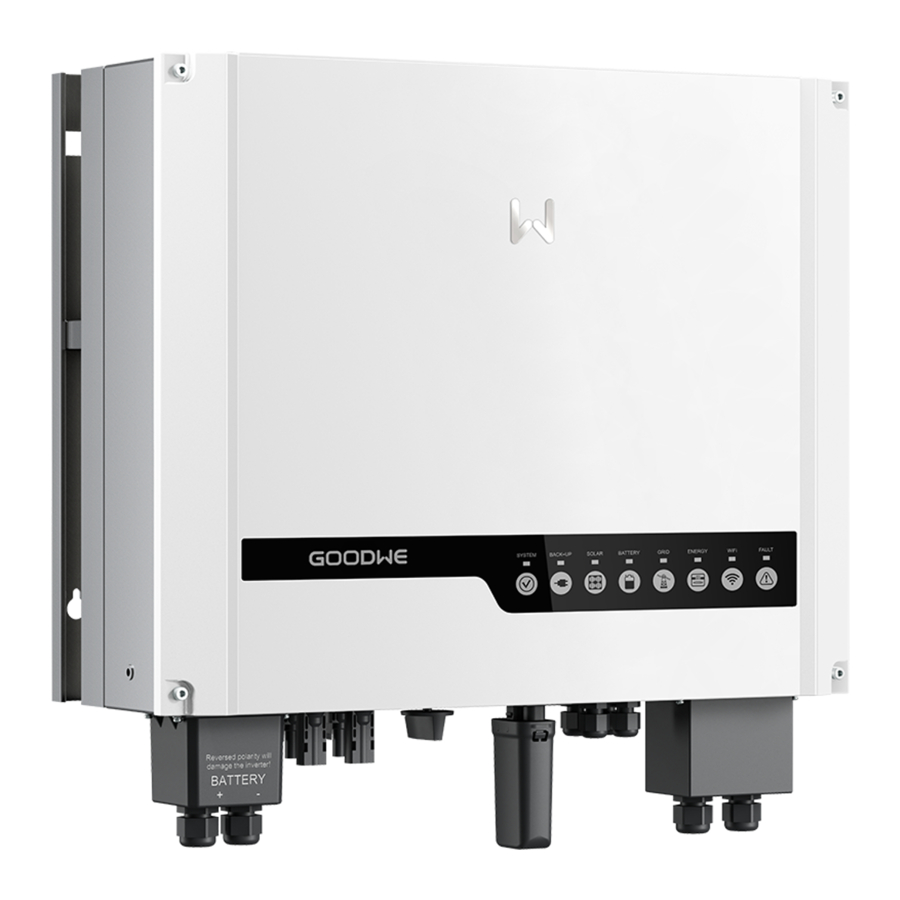
Product Overview

- Battery input terminals
- PV input terminals
- DC Switch (Optional)
- WiFi antenna port
- USB port
- RS485 port
- AC output terminals
- LED lights
Selecting The Mounting Location
Mounting location should be selected based on the following aspects:
- The installation method and mounting location must be suitable for the inverter's weight and dimensions.
- Mount on a solid surface.
- Select a well ventilated place sheltered from direct sun radiation.
- Install vertically or tilted backward by max 15°. The device cannot be installed with a sideways tilt. The connection area must point downwards. Refer to Figure 3.3-1.

- In order to achieve optimal performance, the ambient temperature should be lower than 45°C.
- For the convenience of checking the LED lights and possible maintenance activities, please install the inverter at eye level.
- Inverters should NOT be installed near inflammable and explosive items. Any strong electro-magnetic equipment should be kept away from installation site.
- Product label and warning symbol shall be clear to read after installation.
- Please avoiding direct sunlight, rain exposure, snow lay up when installing.

- In consideration of heat dissipation and convenient dismantlement, the minimum clearances around the inverter should be no less than the following value (see Figure 3.3-2):


Mounting
Remember that this inverter is heavy! Please be carefully when lifting out from the package.
- Use the wall-mounted bracket as a template and drill 6 holes on the wall, 10 mm in diameter and 80 mm deep. Refer to Figure 3.4-1.

- Fix the wall-mounted bracket on the wall with six expansion bolts in accessory bag.
- Carry the inverter by holding the heat-sink two sides. Refer to Figure 3.4-2.

- Place the inverter on the wall-mounted bracket. Refer to Figure 3.4-3, Figure 3.4-4.


Electrical Connection
AC Output Connection
Before connecting to Grid and Load, please install a separate AC breaker (250VAC/30A) between inverter and Grid. This will ensure the inverter can be securely disconnected during maintenance.
 It's very important for system safety and efficient operation to use appropriate cable for AC connection. To reduce risk of injury, please use the proper recommended cable size. Refer to Figure 4.1-1.

| Grade | Descriptio | Value |
| A | O.D. | 10~12mm |
| B | Conductor Material Sectional Area | 3~4mm2 |
| C | Bare Wire Length | 10mm around |
Please follow below steps to implement AC connection:
- Check the grid voltage and frequency at the connection point of the inverter. It should meet GoodWe product Spec.
- Measure the impedance between neutral cable and earth cable, make sure it is not excess than 10 ohm.
- Disconnect AC breaker between inverter and Grid.
- Disconnect screw cap from insulator.
- Disconnect waterproof ring from insulator.
- Put the cable through the components in this order: screw cap, waterproof ring, insulator, AC cover and AC terminal. Refer to Figure 4.1-2.

- Compress the terminal head by professional tool and screw down screw cap slight. Refer to Figure 4.1-3, Figure 4.1-4.


- Insert AC terminals into the corresponding holes and fasten them by screwdriver (Suggest: diameter of the cutter bar is 4mm, torsion: 8~12Kg-f.cm), then fasten AC cover with pan head screws in accessory bag. Refer to Figure 4.1-5, Figure 4.1-6, Figure 4.1-7.


- Screw down screw cap again.


PV Connection
![warning]() Before connecting the PV panels, ensure the plug connectors have the correct polarity. Incorrect polarity could permanently damage the inverter.
Before connecting the PV panels, ensure the plug connectors have the correct polarity. Incorrect polarity could permanently damage the inverter.- Check the short-circuit current of the PV string. The total short-circuit current must not exceed the inverter's maximum PV current.
- PV array should not be connected to the grounding conductor.
- Must be use DC plugs in accessory bag.
- The minimum insulation resistance to ground of the PV pannels must exceed 19.33kΩ, there is a risk of shock hazard if the requirement of minimum resistance is not met.
There are two types of DC plugs, SUNCLIX and MC4 series. Please refer to Figure 4.2-1.


Installation instruction of SUNCLIX please refer to Figure 4.2-2.

Installation instruction of MC4 please refer to Figure 4.2-3.
Battery Connection
Before connecting to battery, please install a separate DC breaker (60A for GW3648D-ES and 120A for GW5048D-ES) between inverter and battery. This will ensure the inverter can be securely disconnected during maintenance.
![warning]() Reversed polarity will damage the inverter!
Reversed polarity will damage the inverter!- Be aware of electric shock and chemical hazards!
- It is a normal phenomenon that electric arc occurs when connecting battery to the inverter without use a DC breaker.
- It's very important for system safety and efficient operation to use appropriate cable for battery connection. To reduce risk of injury, please use the proper recommended cable size. Refer to Figure 4.3-1.


| Grade | Description | Value |
| A | O.D. | 10~12mm |
| B | Conductor Material Sectional Area | 20~25mm2 |
| C | Bare Wire Length | 10mm around |
- Suggestion: if the battery is to be installed indoor, for details please refer to battery manufacture's user manual.
- Suggestion: Batteries must be installed with a distance to each other, details please refer to battery manufacture's user manual.
- As for the number of cells used, it will be decided by customer's choice, the choice must comply with the followed requirement: the rated voltage is 48V.
Please follow below steps to implement battery connection:
- Check the nominal voltage of batteries. The nominal output voltage should meet GoodWe product Spec.
- Disconnect DC breaker between inverter and battery.
- Disconnect screw cap from insulator.
- Disconnect waterproof ring from insulator.
- Put the cable through the components in this order: screw cap, waterproof ring, insulator, battery cover and battery terminal. Refer to Figure 4.3-2.

- Compress the terminal head by professional tool and screw down screw cap slight. Refer to Figure 4.3-3, Figure 4.3-4.


- Put battery terminals into the corresponding holes and fasten them by screwdriver and spanner (recommended torsion: 50~70Kg- f.cm), then fasten battery cover with pan head screws in accessory bag. Refer to Figure 4.3-5, Figure 4.3-6, Figure 4.3-7.


- Screw down screw cap again.


RS485 Connection
RS485 interfaces are used for EzConverter and EzMeter communication. The cable length should not exceed 800m. For the connection methods of RS485 please refer to the next two chapters.

Please follow below steps to implement RS485 connection of inverter side:
- Remove RS485 waterproof assembly from inverter.
- Disconnect screw cap from insulator.
- Disconnect waterproof ring from insulator.
- Put the cable through the components in this order: screw cap, waterproof ring, insulator, RS485 cover. Refer to Figure 4.4-1.
- Put cable cores insert into the corresponding slots and compress the crystal head by professional tool, then screw down screw cap slight. Refer to Figure 4.4-1.
- Put crystal head insert into the corresponding inner slots of inverter.
- Fasten RS485 waterproof assembly to inverter.
- Screw down screw cap again.
EzMeter Connection
EzMeter can detect the current magnitude and direction, to control the working condition of inverter. Inverter and EzMeter communication via RS485, The cable length should not exceed 800m.

For the connection method of single phase EzMeter refer to Figure 4.5-1.

For the connection method of three phases EzMeter refer to Figure 4.5-2.
EzConverter Connection
(optional)
It is needed to configure EzConverter if lithium battery is used in the system, to communicate with battery BMS.
Inverter and EzConverter communication via RS485, lithium battery and EzConverter communication via RS485 or CAN or RS232 (depend on Li-Ion battery communication type).The cable length should not exceed 2m.
Choose corresponding dial-up circuit of lithium battery, according to dial-up protocol comparison table of lithium battery from user manual.
- Lithium battery communication connects to EzConverter via RS485 interface if lithium battery communication protocol is RS485. Refer to Figure 4.6-1.

- Lithium battery communication connects to EzConverter via CAN interface if lithium battery communication protocol is CAN. Refer to Figure 4.6-2.

- Lithium battery communication connects to EzConverter via RS232 interface if lithium battery communication protocol is RS232. Refer to Figure 4.6-3.


EzConverter work status as below table 4.6-1.
| TABLE 4.6-1 | |||
| Silk-Screen | LED Color | EzCoverter Status Note | LED Display Status |
| Power | Green | Powered on | Constant on |
| Inverter | Yellow | Communicate with Inverter | Blink |
| RS485 | Yellow | Communication OK | Blink |
| CAN | Yellow | Communication OK | Blink |
| RCR | Yellow | Received command from RCR | Blink |
| RS232 | Yellow | Communication OK | Blink |
WiFi Connection

Install the antenna to inverter. Refer to Figure 4.7-1.
WiFi Reset & Reload

WiFi reload function is used to change the WiFi configuration to default value. Please reconfigure the WiFi as per WiFi configure illustration after using the function.
- Long press (more than 5s, less than 8s) the touch switch until the LED WiFi displays "Blink 0.5s on 0.5s off", stop pressing and WiFi reset is successful. Refer to Figure 4.8-1
- Long press (more than 20s, less than 30s) the touch switch until the LED WiFi display s"Blink 0.5s on 0.5s off" twice, stop pressing and WiFi reload is successful. Refer to Figure 4.8-1.
USB Connection

The USB communication is used for firmware update only!
Please follow below Figure 4.9-1 to implement USB connection
LED Lights Illustration
| Inverter Status | LED Color | Inverter Status Note | LED Display Status |
| WiFi | Yellow | WiFi Reset or Reload OK | Blink 0.2s on 0.2s off |
| WiFi Router NG | Blink 0.5s on 0.5s off | ||
| WiFi Server NG | Blink 2.5s on 2.5s off | ||
| WiFi Server OK | Constant on | ||
| Normal | Green | Normal | Constant on |
| Checking | Blink 0.5s on 0.5s off | ||
| Fault | Red | Fault | Constant on |
| Grid Fault | Blink 2s on 2s off | ||
| Sale | Blue | Generate to grid | Constant on |
| Feeding to Grid is Off | Blink 2s on 2s off | ||
| Buy | Blue | Consumption from grid | Constant on |
| Charge | Blue | Battery Charging | Constant on |
| Discharge | Blue | Battery Discharging | Constant on |
| Bat Low | Red | Battery Low / Bad / Disconnect | Blink 1s on 1soff |
EzManage Operation Illustration
ES Series inverter has no LCD screen, it can be controlled via mobile device with the APP software (EzManage).
Download and Install

- Android market: http://apk.hiapk.com/appinfo/com.goodwe.EzManage
Besides, through scan the QR code to be installed too.

Google play

Android market
Setting
If this is your first time to install GoodWe Hybrid Inverter, please first connect the battery and solar panels to the inverter and keep the inverter off-grid, then you can set the inverter in "Setting" menu through Ezmanage with the following steps. After finishing the setting, connect to grid, Then the inverter starts to work.
- WiFi communication
 | Plan 1.Connect the inverter directly! Please choose the SSID of inverter (Solar-WiFi as default, initial password: 12345678) and join it. |
| Plan 2.Connect through wireless router! If inverter has joined local WiFi network, you can choose the SSID of WiFi router and join it. |
If you have any questions, please refer to WiFi Connection Guide.
- Select "Safety Country "
 |
Attention: |

- Set "Synchronize Time"
 | Click to synchronize time setting with your monitoring device |
- "Battery Selection"
 | Battery Setting |
 |
|
|
- Battery Management
(If you have already install a GoodWe EzMeter, you can skip to next step, because GoodWe Hybrid Inverter will automatically control the Battery charging and discharging based on your demand.)
 | Battery Setting |
 | Grid Charge Time: During this time period, gird will charge battery automatically. |
| Grid Charge Power: Set grid charge power limits(0-50%). | |
| Battery Discharge Time: During this time period, the battery will discharge. | |
| Battery Discharge Power: Set battery discharge power limits(0-100%). | |
| Attention: If there is overlap between charge time and discharge time, charge is preferred. |
- "Function Setting"
 | Advanced Settings |
 | Feeding To Grid: When the switch is "yes", excess energy of PV can feed to grid. |
| Shadow Scan: When switch is "on", it can resolve the multiple wave problems of PV pannels. | |
| PV Charge Without Grid: When switch is "on", PV can charge battery without grid. This | |
| Function can be set in off-grid and must have PV. | |
| Back-up Function: When switch is "on", it allows the Back-up port to output. | |
| Start Back-up Output: When grid is unreachable, we can start Back-up manually. |
Current Data Display

Historical Data Display
 | |
 | Solar Yield
|
 | Check the battery level
|
 | |


Work Modes
ES series inverters have the following main work modes based on different conditions:
| Mode1: Energy produced by the PV system is preferred for local load. And the excess energy is first used for charging batteries, then feeding to the grid. |  | |
| Mode2: If there is no PV, battery energy is used for local load first, the grid also can supply when the battery capacity is not enough. |  | |
| Mode3: If the grid is fault or there is no grid, the system can still work, PV and batteries supply energy for local load. |  | |
| Mode4: The battery can be charged by the grid, time and power of battery charging can be set up flexibly. |  | |
Error Messages
An error message will be displayed on the APP if a fault occurs.
Table 8-1 is the Description of Error Message
| Error message | Description |
| Utility Loss | Grid disconnected |
| Fac Failure | Grid frequency no longer within permissible range |
| PV Over Voltage | Overvoltage at DC input |
| Over Temperature | Overtemperature on the case |
| Isolation Failure | Ground insulation impedance is too low |
| Ground I Failure | Overhigh ground leakage current |
| Relay-Check Failure | Relay self-checking failure |
| DC Injection High | Overhigh DC injection |
| EEPROM R/W Failure | Memory chip failure |
| SPI Failure | Internal communication failure |
| DC Bus High | Overhigh BUS voltage |
| AC HCT Failure | Output current sensor failure |
| GFCI Failure | Detection circuit of ground leakage current failure |
| Vac Failure | Grid voltage no longer within permissible range |
| Battery Over Temperature | Battery Over Temperature |
| Battery Under Temperature | Battery Under Temperature |
| Battery Cell Voltage Differences | Li-Ion Battery Cell Voltage Differences |
| Battery Over Total Voltage | Li-Ion Battery Over Total Voltage |
| Battery Discharge Over Current | Battery Discharge Over Current |
| Battery Charge Over Current | Battery Charge Over Current |
| Battery Under SOC | Battery Capacity Low |
| Battery Under Total Voltage | Battery Under Total Voltage |
| Battery Communication Fail | Battery Communication Fail |
| Battery Output Short | Battery Output Short |
Table 8-1
Technical Parameters
| Model | GW5048D-ES | GW3648D-ES |
| Solar | ||
| * Max. DC power(W) | 5400 | 4200 |
| Max. DC voltage (V) | 580 | 580 |
| MPPT voltage range (V) | 125~550 | 125~550 |
| Starting voltage (V) | 125 | 125 |
| Max. DC current (A) | 15/15 | 15/15 |
| DC overcurrent protection(A) | 20 | 20 |
| No. of DC connectors | 2 | 2 |
| No. of MPPTs | 2(can parallel) | 2(can parallel) |
| DC overvoltage category | Category Ⅱ | |
| DC connector | SUNCLIX / MC4 (Optional) | |
| Battery | ||
| Battery Type | Lead-acid or Li-Ion | Lead-acid or Li-Ion |
| Battery Rated voltage (V) | 48 | 48 |
| MAX Discharge power (W) | 4600 | 4600 |
| Charge current (A) | 5-50 A continuous, programmable | 5-50 A continuous, programmable |
| Battery capacity (Ah) | >100AH(depending requirement) | >100AH(depending requirement) |
| Charging curve | 3-stage adaptive with maintenance | 3-stage adaptive with maintenance |
| Charging voltage | 57V | 57V |
| Battery temperature compensation | included(Li-Ion) | included(Li-Ion) |
| Battery voltage sense | integrated | integrated |
| Current shunt | integrated | integrated |
| AC Output Data | ||
| Norminal AC power(W) | 4600 | 3600 |
| Max. AC power(W) | 4600 | 3600 |
| Peak power (Back-up)(W) | 1.5x Pnom, 10sec | 1.5x Pnom, 10sec |
| Max. AC current(A) | 20 | 16 |
| AC overcurrent protection(A) | 30 | 24 |
| Norminal AC output | 50/60Hz; 230Vac | |
| AC output range | 45~55Hz/55~65Hz; 180~270Vac | |
| AC output (Back-up) | 230Vac ±2%, 50Hz ±0.2%, THDv<3%(linear load) | |
| THDi | <1.5% | |
| Power factor | 0.9 leading~0.9 lagging | |
| Grid connection | Single phase | |
| AC overvoltage category | Category Ⅲ | |
| Efficiency | ||
| Max. efficiency | 97.6% | 97.6% |
| Euro efficiency | 97.0% | 97.0% |
| MPPT adaptation efficiency | 99.9% | |
| Protection | ||
| Residual current monitoring unit | Integrated | |
| Anti-islanding protection | Integrated | |
| DC switch(PV) | Integrated (optional) | |
| AC over current protection | Integrated | |
| Insulation monitoring | Integrated | |
| Certifications&Standards | ||
| Grid regulation | VDE4105, VDE 0126-1-1+A1, G83/2, G59/2, AS4777.2/.3, IEC62109-2 | |
| Safety | IEC62109-1&-2, AS3100, IEC62040-1 | |
| EMC | EN61000-6-1, EN61000-6-2, EN61000-6-3, EN61000-6-4, EN61000-3-11, EN61000-3-12 | |
| General Data | ||
| Dimensions (WxHxD) | 516*440*184mm | 516*440*184mm |
| Weight (kg) | 30 | 28 |
| Mounting | Wall-mounted Bracket | |
| Ambient temperature range | -25~60°C (>45°C derating) | |
| Relative humidity | 0~95% | |
| Moisture location category | 4K4H | |
| Max. operating altitude | 2000m | |
| Protection degree | IP65 | |
| Environment category | Outdoor & indoor | |
| External environment pollution degree | Grade1, 2, 3 | |
| Topology | Transformerless | |
| Standby losses(W) | <8 | |
| Cooling | Nature convection | |
| Noise emision(dB) | <25 | |
| Display | LED light & APP | |
| Communication | USB2.0 or WiFi | |
| Standard warranty(years) | 5/10/15/20/25 (optional) | |
* It is recommended that the total peak power of PV strings should not exceed 130% of maximum DC power of inverter listed in the table.
Note
Overvoltage category definition
Category I: applies to equipment connected to a circuit where measures have been taken to reduce transient overvoltage to a low level.
Category II: applies to equipment not permanently connected to the installation. Examples are appliances, portable tools and other plug-connected equipment;
Category III: applies to fixed equipment downstream of and including, the main distribution board. Examples are switchgear and other equipment in an industrial installation;
Category IV: applies to equipment permanently connected at the origin of an installation (upstream of the main distribution board). Example are electricity meters, primary overcurrent protection equipment and other equipment connected directly to outdoor open lines.
| Moisture location category definition | |||
| Moisture parameters | Level | ||
| 3K3 | 4K2 | 4K4H | |
| Temperature Range | 0~+40℃ | -33~+40℃ | -20~ +55°C |
| Humidity Range | 5%~85% | 15%~100% | 4%~100% |
Environment category definition
Outdoor: the ambient air temperature is -20~50°C, Relative humidity range is 4% to 100%, applied to PD3
Indoor unconditioned: the ambient air temperature is -20~50°C, Relative humidity range is 5% to 95%,applied to PD3
Indoor conditioned: the ambient air temperature is 0~40°C, Relative humidity range is 5% to 85%,applied to PD2
Pollution degree definition
Pollution degree 1: No pollution or only dry, non-conductive pollution occurs. The pollution has no influence.
Pollution degree 2: Normally only non-conductive pollution occurs. Occasionally, however, a temporary conductivity caused by condensation must be expected.
Pollution degree 3: Conductive pollution occurs, or, dry, non-conductive pollution occurs which becomes conductive due to condensation which is expected.
Pollution degree 4: Persistent conductive pollution occurs, for example, the pollution cause by conductive dust, rain and snow.
Global Service Hotline: +86 4009-281-333
GoodWe(China)
No.189 Kunlunshan Rd., SND,
Suzhou, 215163, China
T: +86 512 6239 6771
service@goodwe.com.cn
www.goodwe.com.cn
GoodWe(Europe)
Mürwikerstr. 59
24943 Flensburg Germany
T: +49 461 5897 0235
europe@goodwe.com.cn
www.goodwe.de
GoodWe(Australia)
74 Tarana Avenue,
Glenroy VIC 3046, Australia
T: +61 3 9972 9938
australia@goodwe.com.cn
www.goodwe.de
GoodWe(Netherlands)
Zevenwouden 194,
3524 CX Utrecht, the Netherlands
T: +31 6 1988 6498 +31 6 1784 0429
service@goodwe.com.cn
www.goodwe.com.cn
GoodWe(UK)
93 Caversham Place
Sutton Coldfield B73 6HW
T:+44 12 1238 0053
uk@goodwe.com.cn
www.goodwe.com.cn
Documents / Resources
References
Download manual
Here you can download full pdf version of manual, it may contain additional safety instructions, warranty information, FCC rules, etc.
Advertisement


Need help?
Do you have a question about the ES Series and is the answer not in the manual?
Questions and answers