Table of Contents
Advertisement
Quick Links
User Manual
SW-4000Q-10GE
4CMOS Prism Linescan Camera
Document Version: 1.0
SW-4000Q-10GE_Ver.1.0 _Apr.2019
Thank you for purchasing this product.
Be sure to read this manual before use.
This manual includes important safety precautions and instructions on how to operate the unit. Be sure to read
this manual to ensure proper operation.
The contents of this manual are subject to change without notice for the purpose of improvement.
© 2019 JAI
Advertisement
Table of Contents

Related Manuals for JAI SW-4000Q-10GE


Summary of Contents for JAI SW-4000Q-10GE
- Page 1 This manual includes important safety precautions and instructions on how to operate the unit. Be sure to read this manual to ensure proper operation. The contents of this manual are subject to change without notice for the purpose of improvement. © 2019 JAI...
-
Page 2: Table Of Contents
SW-4000Q-10GE Contents Notice/Warranty/Certifications EEN (Exposure Enable) Function Test Pattern Function Usage Precautions Features Color Space Conversion Counter And Timer Control Function Parts Identifications Chromatic Aberration Correction Connecting Rotary Encoders Preparation Frame Start Trigger Preparation Process Binning Function Step 1:Installing the Software... -
Page 3: Notice/Warranty/Certifications
The material contained in this manual consists of information that is proprietary to JAI Ltd., Japan and may only be used by the purchasers of the product. JAI Ltd., Japan makes no warranty for the use of its product and assumes no responsibility for any errors which may appear or for damages resulting from the use of the information contained herein. - Page 4 SW-4000Q-10GE Supplement The following statement is related to the regulation on “ Measures for the Administration of the control of Pollution by Electronic Information Products “ , known as “ China RoHS “. The table shows contained Hazardous Substances in this camera.
-
Page 5: Usage Precautions
SW-4000Q-10GE Usage Precautions Notes on cable configurations The presence of lighting equipment and television receivers nearby may result in video noise. In such cases, change the cable configurations or placement. Notes on LAN cable connection Secure the locking screws on the connector manually, and do not use a driver. - Page 6 SW-4000Q-10GE Phenomena specific to CMOS image sensors The following phenomena are known to occur on cameras equipped with CMOS image sensors. These do not indicate malfunctions. • Aliasing When shooting straight lines, stripes, and similar patterns, vertical aliasing (zigzag distortion) may appear on the monitor.
-
Page 7: Features
SW-4000Q-10GE Features The SW-4000Q-10GE is a 4CMOS line scan camera using four 4096 pixel line sensors mounted on a prism, for the R, G, B and NIR channels. The camera outputs digital data in single-stream or dual-stream via 10 GigE interface. -
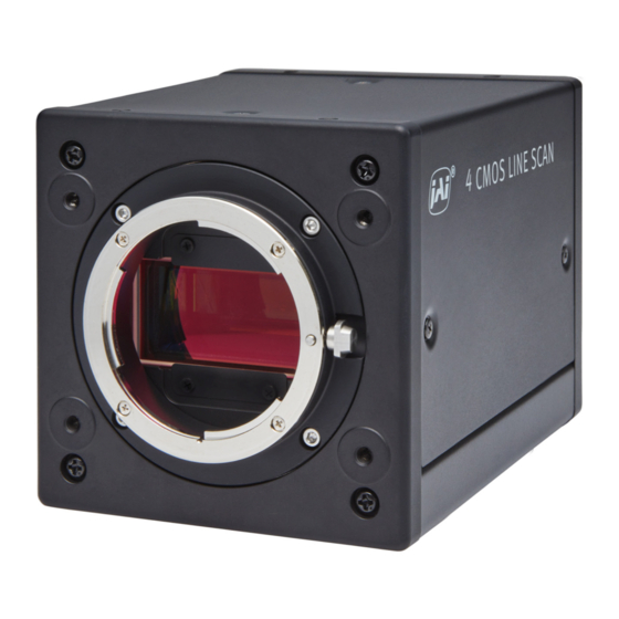
Page 8: Parts Identifications
SW-4000Q-10GE Parts Identification ⑥ ② ⑦ ⑤ ④ ③ ① ⑧ ⑧ ① Lens mount (M52-mount /F-mount) Mount a M52-mount lens, F-mount lens, etc. here. ❖ Before mounting a lens, be sure to refer to “Step 2:Connecting Devices” and confirm the precautions for attaching a lens and the supported lens types. - Page 9 SW-4000Q-10GE ② POWER/TRIG LED Indicates the power and trigger input status. LED status and camera status Light Status POWER/TRIG LED (Lit amber) Camera initializing. (Lit green) Camera in operation. (Blinking green) During operation in trigger mode, trigger signals are being input * The blinking interval is not related to the actual input interval of the external trigger.
- Page 10 SW-4000Q-10GE ⑥ DC IN/TRIG connector(12-pin round) Connect the cable for a power supply (optional) or for DC IN / trigger IN here. HR10A-10R-12PB(71)(Hirose Electric or equivalent ) Pin No. Signal Description Input/Output Power In DC In DC 10 V ~ 25 V...
- Page 11 SW-4000Q-10GE Recommended external input circuit diagram (reference example) User side JAI Camera side CAMERA User side side ⑦ AUX connector(10-pin) Camera side:3260-10S3(55)(Hirose Electric or equivalent ) Cable side :3240-10P-C(50)(Hirose Electric or equivalent ) Pin No. Signal Description Input/Output TTL_OUT2 Line 8...
-
Page 12: Preparation
When using the camera for the first time, install the software for configuring and controlling the camera (eBUS SDK for JAI) on the computer. ❖ When you install eBUS SDK for JAI, eBUS SDK for JAI player will also be installed. Download the eBUS SDK for JAI from the JAI website. -
Page 13: Step 2:Connecting Devices
SW-4000Q-10GE Step 2: Connecting Devices (or direct connection) Camera body ④ Network card ③ LAN cable ①Lens ② Direct connection Switching hub ⑤ DC IN/trigger IN connection cable ⑥ AC adapter (not supplied) ① Lens ・Attach an M52-mount lens or F-mount lens. - Page 14 SW-4000Q-10GE ③ LAN cable Connect a LAN cable to the RJ-45 connector. ・ The camera supports the following Ethernet standards. (1000Base-T, 2.5GBase-T, 5GBase-T, 10GBase-T) ・ The longest cable length varies depending on the type of LAN cable and the Ethernet standard.
-
Page 15: Step 3:Verifying Camera Operation
Step 4: Verifying the Connection between the Camera and PC Verify whether the camera is properly recognized via Control Tool. Connecting the Camera to Control Tool Startup eBUS Player for JAI eBUS Player for JAI startup screen appears. — 15 —... - Page 16 SW-4000Q-10GE Select the camera you want to configure. Push Select / Connect button The connected camera is listed. Please select one camera. — 16 —...
- Page 17 SW-4000Q-10GE Check that the settings of the selected camera are displayed. Push the Device control button. The screen shown below will be displayed. In this window you can adjust various settings of the camera. This completes the procedure for verifying whether the camera is properly recognized and whether control and settings configuration are possible.
-
Page 18: Step 5:Changing The Camera Settings
SW-4000Q-10GE Step 5 Configuring Basic Settings for the Camera ■Control via External Triggers When Controlling the Exposure Time Using Specified Exposure Times Configure the settings as follows. Item Setting value / selectable range Trigger Mode Trigger Selector Line Start Trigger Source... - Page 19 SW-4000Q-10GE ■Control Without External Triggers When Controlling the Exposure Time Using Specified Exposure Times Configure the settings as follows. Item Setting value / selectable range Trigger Mode Exposure Mode Timed (control via exposure time) Exposure Time Varies depending on settings.
-
Page 20: Step 6:Adjusting The Image Quality
SW-4000Q-10GE Step 6: Adjusting the Image Quality Display the camera image and adjust the image quality. Displaying the Image Display the image captured by the camera. When you push [Play] button, the camera image appears in right area. *) By default settings, the video in the visible region are displayed. -
Page 21: Step 7:Saving The Settings
The white balance is automatically adjusted. Step 7: Saving the Settings The setting values configured in the player (eBUS SDK for JAI) will be deleted when the camera is turned off. By saving current setting values to user memory, you can load and recall them whenever necessary. - Page 22 SW-4000Q-10GE Select [UserSetSave], and click [UserSetSave]. The current setting values are saved as user settings. ■ To load user settings Stop image acquisition. User settings can only be loaded when image capture on the camera is stopped. Select the settings to load (UserSet1 to UserSet3) in [UserSetSelector].
-
Page 23: Main Functions
SW-4000Q-10GE Main Functions Valid Input / Output Combinations The following signals can be used as sources for each output destination (Trigger Selector, Line Selector, Pulse Generator Selector). You can also connect two different sources to NAND paths in the GPIO and reuse the signal generated there as a source for a different selector. -
Page 24: Gpio(Digital Input/Output Settings)
SW-4000Q-10GE GPIO (Digital Input / Output Settings) The unit can input/output the following signals to and from external input/output connectors. Line1 TTL Out 1 DC IN / TRIG IN connector (12 pin) External Line8 TTL Out 2 AUX connector (10 pin) -
Page 25: Pixel Format
SW-4000Q-10GE Pixel format This camera can capture the image in the visible region and the near infrared region (NIR) simultaneously. There are the following two ways of sending data of the two captured images from the camera. 1. Single-stream output Stream 0 …... - Page 26 SW-4000Q-10GE Note Stream 0, Stream 1 are two UDP streams, each assigned a different port number. The assigned port number can be confirmed with the following settings. In [TransportLayerControl] - [GevStreamChannelSelector], select the stream whose port number you want to check, the port number will be displayed in [GevSCSP].
-
Page 27: Exposuremode
SW-4000Q-10GE Exposure Mode The following operation modes are available on the camera. Operation mode Exposure Mode Trigger Mode Timed Trigger Width Image Output Timing ■ Trigger Control In this camera, the following control is performed by the external trigger signal. - Page 28 SW-4000Q-10GE ■ When [Exposure Mode] is [OFF] Trigger Exposure Active Readout Period from Delay Time from Exposure Active Trigger Trigger to Expousre Active Readout Falling Pixel Format Width Period[A] Exposure Non Active[B2] Period[D] to Readout (μs) (*)(**) Active[B1] (μs) (μs) Start[C] (μs)
- Page 29 SW-4000Q-10GE ■ When [Exposure Mode] is [Timed] Trigger Exposure Active Readout Period from Delay Time from Exposure Active Trigger Trigger Rising to Readout Falling Period[A] Pixel Format Width Exposure Active period[D] to Readout (*)(**) Rising[B] (μs) (μs) rising[C] (μs) (μs) 4096 14.70...
- Page 30 SW-4000Q-10GE ■ When [Exposure Mode] is [Trigger Width] Trigger Exposure Active Readout Period from Delay Time from Delay Time from Exposure Active Trigger Trigger Rising to Readout Trigger Falling Falling Period[A] Pixel Format Width Exposure Active period[D] to Exposure to Readout...
-
Page 31: Pixel Sensitivity Correction
SW-4000Q-10GE Pixel Sensitivity Correction Correct variations between the sensor’s pixels. Calibration must be performed within the camera and correction data must be created beforehand. DSNU (Pixel Black Correct) / PRNU (Pixel Gain Correct) can be reduced using that correction data. We recommend performing calibration and creating correction data whenever the line rate setting is changed significantly. -
Page 32: Gain Control
SW-4000Q-10GE Gain Control The following gain functions are available on the camera. • Analog base gain • Digital gain ■ Analog base gain Analog base gain (ABG) is gain that is performed to the analog video signal output from the sensor. -
Page 33: Lookup Table (Lut)
SW-4000Q-10GE Lookup Table(LUT) The LUT function is used to generate a non-linear mapping between signal values captured on the sensor and those that are output from the camera. You can specify the output curve using 257 setting points (indexes). ■ To use the LUT function Configure the settings as follows. -
Page 34: Gamma Function
SW-4000Q-10GE Gamma Function The gamma function corrects the output signals from the camera beforehand (reverse correction), taking into consideration the light-emitting properties of the monitor display. As the light-emitting properties of the monitor are not linear, the entire image may be darker or the gradation in the dark areas may be less noticeable when camera outputs are displayed without processing. -
Page 35: Shadingcorrection
SW-4000Q-10GE Shading Correction The shading correction is a function that corrects non-uniformity (i.e., shading) in the amount of light generated by the lens and lighting equipment. The following shading correction modes are available on the camera。 ■ Flat shading correction Correct so that the part with the highest luminance level in the screen is taken as the reference and the other part is adjusted to this luminance level. -
Page 36: Variable Line Rate
SW-4000Q-10GE Variable Line Rate You can set the line rate to 1L or more. This function can be used to match the scanning speed of the camera to the feeding speed of the object or to lengthen the accumulation time to increase sensitivity. -
Page 37: Color Space Conversion
Default Caution If you set the color space to XYZ or HSI, eBUS Player for JAI will not display the images captured by the camera properly. To display them properly, XYZ- or HSI-compatible image processing must be performed on the computer side. -
Page 38: Counter And Timer Control Function
SW-4000Q-10GE Counter And Timer Control Function This camera supports only the counter function. The counter function counts up change points in the camera’s internal signals using the camera’s internal counter, and reads that information from the host side. This function is useful for verifying error conditions via the count value using internal camera operations. - Page 39 SW-4000Q-10GE ■ Internal camera blocks Counter0 Counter Event detection Line Trigger At event occurrence or count up Counter1 Counter Event detection Line Start At event occurrence or count up Counter2 Counter Event detection Exposure Start At event occurrence or count up ・...
-
Page 40: Chromatic Aberration Correction
SW-4000Q-10GE Chromatic Aberration Correction This Function corrects for the chromatic aberration of magnification caused by the lens (i.e., when the size of the image differs at the focal point for each color (RGB)). You can save correction data for three types of lenses. This function assumes that the amount of deviation between the left and right is identical. -
Page 41: Frame Start Trigger
SW-4000Q-10GE If necessary, enable the low-pass filter for the signal to prevent unintended operations due to signal noise from the rotary encoder. Specify the number of cycles from a range of 0 to 15 (0 to 150 ns). If necessary, specify the strobe length of the generated signal. -
Page 42: Binning Function
SW-4000Q-10GE Binning Function The binning function allows you to combine the signal values of clusters of adjacent pixels to create improved virtual pixels. Using the function results in images with lower pixel resolution and higher sensitivity. This camera performs vertical binning via digital addition in the sensor. -
Page 43: Chunk Data Function
SW-4000Q-10GE Chunk Data Function The Chunk Data function adds camera configuration information to the image data that is output from the camera. Embedding camera configuration information in the image data allows you to use the serial number of the camera as a search key and find specific image data from among large volumes of image data. -
Page 44: Event Control Function
SW-4000Q-10GE Event Control Function The Event Control Function is a function that outputs a signal change point inside the camera as information indicative of an event occurrence (event message) by using GVCP (GigE Vision Control Protocol). ■ Flow from detecting an event to sending an event message... -
Page 45: Action Control Function
SW-4000Q-10GE Action Control Function The Action Control Function is a function that executes the pre-configured action when the camera receives action commands. Action commands can send both unicast and broadcast messages and give instructions for actions to multiple cameras simultaneously by broadcasting them. -
Page 46: Setting List
SW-4000Q-10GE Setting List Feature Properties Item Setting range Default value Description a) Device Control Display/configure information related to the device. Device Vendor Name ー "JAI Corporation" Display the manufacturer name. Device Model Name ー SW-4000Q-10GE Display the model name. Device Manufacturer Info ー... - Page 47 SW-4000Q-10GE Item Setting range Default value Description b) ImageFormatControl Configure image format settings. WidthMax ー 4096 Display the maximum image width. HeightMax ー 4096 Display the maximum image height. Width BinningHorizontal 1: 4096 Set the image width. 16〜4096 step 16 BinningHorizontal 2: 8〜2048 step 8...
- Page 48 SW-4000Q-10GE Item Setting range Default value Description d) Analog Control Set whether to enable auto exposure. IndividualGainMode Off, On In IndividualGainMode, R, G, B, NIR can be configured individually for the entire gain adjustment range of the sensor. GainSelector IndividualGainMode : On ー...
- Page 49 SW-4000Q-10GE Item Setting range Default value Description f) Color Transformation Control Color Transformation Mode RGB, XYZ, HSI Set the output image format. Color Transofrmation RGB Mode Off, sRGB, AdobeRGB, Set the detailed mode when RGB is selected for the color space.
- Page 50 SW-4000Q-10GE Item Setting range Default value Description h) Counter And Timer Control Configure counter settings. (This camera only supports counter functions.) Counter Selector Counter0, Counter1 ー Select the counter. Counter2, Counter3 Counter4, Counter5 Counter Event Source ー Assign the counter event signal for which you want to read the count value to a dedicated counter, and read the value.
- Page 51 SW-4000Q-10GE Item Setting range Default value Description j) Logic Block Control Logic Block Selector Logic Block 0, Logic Block 0 Specifies the Logic Block to configure. Logic Block 1 Logic Block Function Selects the combinational logic Function of the Logic Block to configure.
- Page 52 SW-4000Q-10GE Item Setting range Default value Description l) Event Control Event Selector *) refer to description ー Select the event to send the event message. [setting range] AcquisitionStart, AcquisitionEnd,, FrameStart, FrameEnd, LineStart, LineEnd, ExposureRedStart, ExposureRedEnd, ExposureGreenStart, ExposureGreenEnd, ExposureBlueStart, ExposureBlueEnd, Line1RisingEdge, Line1FallingEdge, Line4RisingEdge, Line4FallingEdge,...
- Page 53 SW-4000Q-10GE Event Line4 Rising Edge Data ー ー When the event [Line4RisingEdge]occurs, the following three data can be checked. Event Line4 Rising Edge ー ー Display the EventID(0x9313). Event Line4 Rising EdgeTimestamp ー ー Displays the Timestamp value when an event occurs.
- Page 54 SW-4000Q-10GE Item Setting range Default value Description m) User Set Control Configure user settings. User Set Selector Default, Default Select the user settings. User Set1, User Set2, User Set3 User Set Load 0(default), 1, 2, 3 ー Load user settings.
- Page 55 SW-4000Q-10GE Item Setting range Default value Description o) Transport Layer Control Display information on transport layer control. PlayloadSize (B) ー 12288 Display the payload size. GevSupportedOptionSelector ー ー Select the supported options for GigEVision. [Setting range] SingleLink, MultiLink, StaticLAG, DynamicLAG, PAUSEFrameReception, PAUSEFrameGeneration,...
- Page 56 SW-4000Q-10GE Item Setting range Default value Description p) PulseGenerator Configure pulse generator settings. ClockPreScaler 1〜4096 Set the division value for the prescaler (12 bit) using PixelClock as the base clock. PulseGeneratorClock (MHz) 0.0181274〜74.25 0.45 Set the clock used for the pulse generator.
- Page 57 SW-4000Q-10GE Item Setting range Default value Description q) Shading Configure shading correction settings. Shading Correction Mode FlatShading, FlatShading Select the shading correction method. ColorShading Shading Mode Off, Set the area to which to save shading correction data. User1, User2, User3 When this is set to [Off], shading correction data is not saved.
-
Page 58: Miscellaneous
SW-4000Q-10GE Miscellaneous Troubleshooting Check the following before requesting help. If the problem persists, contact your local JAI distributor. ■ Power supply and connections Problem Cause and solution The POWER/TRIG LED remains lit amber and Camera initialization may not be complete does not turn green, even after power is due to lack of a network connection. -
Page 59: Specifications
SW-4000Q-10GE Specifications Item SW-4000Q-10GE Four 4096 pixel line sensors Effective pixels 4096 pixel × 4(R, G, B) Image sensor ModeA 7.5 μm × 7.5 μm pixel size ModeB 7.5 μm × 10.5 μm Synchronization Internal Communication Interface 10GBase-T, 5GBase-T, 2.5GBase-T, 1000Base-T RGBa8 66Hz* 〜73kHz (0.1Hz/step) - Page 60 SW-4000Q-10GE BalanceWhiteAuto Off, Once, Exposure Once, Preset5000K, Preset6500K, Preset7500K White balance Adjustment range 4000K 〜 9000K Test pattern Available : Off、White、GrayPattern1(Ramp)、GrayPattern2(Stripe)、ColorBar 1 Pixel sensitivity correction: Pixel correction (DSNU, PRNU) 2 Shading correction: ColorShading, FlatShading Image porcessing 3 LUT: OFF: γ=1.0, ON: 257 points can be set 4 Gamma: 0.45, 0.5, 0.55, 0.6, 0.65, 0.75, 0.8, 0.9, 1.0 (9 steps available)
-
Page 61: Spectral Response
SW-4000Q-10GE Spectral Response Wave length (nm) — 61 —... -
Page 62: Dimensions
SW-4000Q-10GE Dimensions F mount (SW-4000Q-10GE-F) Dimensional tolerance: ± 0.3mm Unit: mm — 62 —... - Page 63 SW-4000Q-10GE M52 mount (SW-4000Q-10GE-M52) Dimensional tolerance: ± 0.3mm Unit: mm — 63 —...
-
Page 64: Comparison Of The Decibel Display And Multiplier Display
SW-4000Q-10GE Comparison of the Decibel Display and Multiplier Display Decibels[db] Multipliers[x] Remarks 0.501 0.562 0.631 0.708 0.794 0.891 1.122 1.259 1.413 1.585 1.778 1.995 2.239 2.512 2.818 3.162 3.548 3.981 4.467 5.012 5.623 6.31 7.079 7.943 8.913 11.22 12.589 14.125 15.849... -
Page 65: User's Record
Camera type: SW-4000Q-10GE Revision: …………… Serial No: …………… Firmware version: …………… For camera revision history, please contact your local JAI distributor. Trademarks • Microsoft and Windows are trademarks or registered trademarks of Microsoft Corporation in the United States and other countries. -
Page 66: Index
SW-4000Q-10GE Index 12-pin round LAN Cable Lens Acquisition Lens mount Adjusting the Black Level Lookup Table Adjusting the Gain Binning Function Network card Black level Output format Camera locking screw holes Chunk Data Function Color Space Conversion Parts Identification Color Transformation Control... -
Page 67: Revision History
SW-4000Q-10GE Revision history Revision Date Changes First version. Apr. 2019 — 67 —...
Need help?
Do you have a question about the SW-4000Q-10GE and is the answer not in the manual?
Questions and answers