Table of Contents
Advertisement
Quick Links
User Manual
SW-4000T-10GE
SW-4000T-SFP
3CMOS Prism Line Scan Camera
Document Version: 2.0
Date: 2023-09-13
Thank you for purchasing this product.
Be sure to read this documentation before use.
This documentation includes important safety precautions and instructions on how to operate the unit. Be sure to read this documentation to ensure
proper operation.
The contents of this documentation are subject to change without notice for the purpose of improvement.
@2023 JAI
Advertisement
Table of Contents

Related Manuals for JAI SW-4000T-10GE


Summary of Contents for JAI SW-4000T-10GE
- Page 1 User Manual SW-4000T-10GE SW-4000T-SFP 3CMOS Prism Line Scan Camera Document Version: 2.0 Date: 2023-09-13 Thank you for purchasing this product. Be sure to read this documentation before use. This documentation includes important safety precautions and instructions on how to operate the unit. Be sure to read this documentation to ensure proper operation.
-
Page 2: Table Of Contents
SW-4000T-10GE | SW-4000T-SFP | User Manual (2.0) Table of Contents Table of Contents Table of Contents About Technical Note Notice/Warranty Notice Warranty Certifications CE Compliance Warning China RoHS Usage Precautions Notes on Cable Configurations Notes on LAN Cable Connection Notes on SFP+ Module Installation... - Page 3 SW-4000T-10GE | SW-4000T-SFP | User Manual (2.0) Table of Contents ② Mounting ③ LAN Cable (SW-4000T-10GE) ➃ Network Card (SW-4000T-10GE) ⑤ DC IN / Trigger IN Connection Cable ⑥ AC Adapter (Power Supply) ⑦ SFP+ Module (SW-4000T-SFP) ⑧ Fiber Optic Cable (SW-4000T-SFP)
- Page 4 SW-4000T-10GE | SW-4000T-SFP | User Manual (2.0) Table of Contents LUT Value Gamma Function To Use the Gamma Function Shading Correction To Use the Shading Correction Function Black Level Correction Variable Line Rate Number of Pixels per Line and Line Rate...
- Page 5 SW-4000T-10GE | SW-4000T-SFP | User Manual (2.0) Table of Contents AcquisitionControl AnalogControl LUTControl ColorTransformationControl DigitalIOControl CounterAndTimerControl EncoderControl Logic Block Control ActionControl EventControl UserSetControl ChunkDataControl TransportLayerControl PulseGenerator Shading Correction Miscellaneous Troubleshooting Power Supply and Connections Image Display Settings and Operations Specifications...
-
Page 6: About Technical Note
Table of Contents About Technical Note Some additional technical information is provided on the JAI website as Technical Notes. In this manual, if a technical note is available for a particular topic, the above icon is shown. Please refer to the following URL for Technical notes. -
Page 7: Notice/Warranty
The material contained in this manual consists of information that is proprietary to JAI Ltd., Japan, and may only be used by the purchasers of the product. JAI Ltd., Japan makes no warranty for the use of its product and assumes no responsibility for any errors which may appear or for damages resulting from the use of the information contained herein. -
Page 8: Warning
SW-4000T-10GE | SW-4000T-SFP | User Manual (2.0) Notice/Warranty connected. Consult the dealer or an experienced radio/TV technician for help. Warning Changes or modifications to this unit not expressly approved by the party responsible for FCC compliance could void the user’s authority to operate the equipment. -
Page 9: China Rohs
SW-4000T-10GE | SW-4000T-SFP | User Manual (2.0) Notice/Warranty China RoHS The following statement is related to the regulation on “Measures for the Administration of the Control of Pollution by Electronic Information Products “, known as “China RoHS“. The table shows contained Hazardous Substances in this camera. -
Page 10: Usage Precautions
SW-4000T-10GE | SW-4000T-SFP | User Manual (2.0) Usage Precautions Usage Precautions Notes on Cable Configurations The presence of lighting equipment and television receivers nearby may result in video noise. In such cases, change the cable configurations or placement. Notes on LAN Cable Connection Secure the locking screws on the connector manually, and do not use a driver. -
Page 11: Notes On Attaching The Lens
SW-4000T-10GE | SW-4000T-SFP | User Manual (2.0) Usage Precautions Notes on Attaching the Lens How to Clean a Sensor Avoiding Dust Particles When attaching the lens to the camera, stray dust and other particles may adhere to the sensor surface and rear surface of the lens. Be careful of the following when attaching the lens. -
Page 12: Features
This camera is a 3CMOS line scan camera using three 4096 pixel line sensors mounted on a prism, for the R, G and B channels. SW-4000T-10GE has a 10 Gigabit Ethernet interface. SW-4000T-SFP has a 10GBASE-R interface that supports 10 Gigabit Ethernet over fiber when an SFP+ module is attached. -
Page 13: Parts Identification
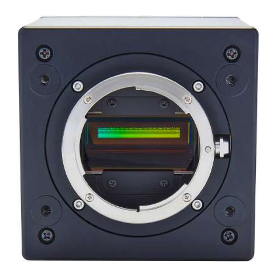
SW-4000T-10GE | SW-4000T-SFP | User Manual (2.0) Parts Identification Parts Identification Note: An exterior view of the F-mount model is shown above. See the "Dimensions " section for exterior views of M52-mount models. ① Lens Mount (M52-Mount or F-Mount) ② POWER/TRIG LED ③... -
Page 14: ② Power/Trig Led
SW-4000T-10GE | SW-4000T-SFP | User Manual (2.0) Parts Identification ② POWER/TRIG LED Indicates the power or trigger input status. Status Camera initializing. Lit amber SW-4000T-SFP: SFP+ module not inserted. Not compatible SFP+ module inserted. The Ethernet Link has not been established. - Page 15 (19.3 W), then power must be connected via both pin pairs. SW-4000T-10GE can also be powered by PoE (Power over Ethernet). TTL Signal specification Output voltage: Low 0.0V, High 5.0V TTL out signal specification (Typ.)
-
Page 16: ④ Aux Connector (10-Pin)
TTL_IN3 Line 13 ⑤ RJ-45 Connector (SW-4000T-10GE) SW-4000T-10GE supports the following Ethernet standards: 1000Base-T, 2.5GBase-T, 5GBase- T, 10GBase-T Depending on the Ethernet standard to be used, the cable type and the maximum cable length are limited. For details, refer to "Step 2: Connect... -
Page 17: ⑥ Sfp+ Connector (Sw-4000T-Sfp)
SW-4000T-10GE | SW-4000T-SFP | User Manual (2.0) Parts Identification ⑥ SFP+ Connector (SW-4000T-SFP) SW-4000T-SFP supports 10GBASE-R Ethernet standards. Requirements specification for SFP+ module: Support 10GBASE-R Support Power level 1 Depending on the Ethernet standard to be used, the cable type and the maximum cable length are limited. -
Page 18: Preparation
When using the camera for the first time, install the software for configuring and controlling the camera (eBUS SDK for JAI) on the computer. Note: When you install eBUS SDK for JAI, eBUS Player for JAI will also be installed. 1. Download the eBUS SDK for JAI from the JAI website (https://www.jai.com/support-... -
Page 19: Step 2: Connect Devices
SW-4000T-10GE | SW-4000T-SFP | User Manual (2.0) Preparation Step 2: Connect Devices SW-4000T-10GE SW-4000T-SFP ① Lens ② Mounting ③ LAN Cable (SW-4000T-10GE) ➃ Network Card (SW-4000T-10GE) ⑤ DC IN / Trigger IN Connection Cable ⑥ AC Adapter (Power Supply) ⑦ SFP+ Module (SW-4000T-SFP) ⑧... -
Page 20: ① Lens
SW-4000T-10GE | SW-4000T-SFP | User Manual (2.0) Preparation ① Lens F-mount or M-52 mount lenses with lens mount protrusions of 13 mm or less can be attached. Caution: The maximum performance of the camera may not be realized depending on the lens. -
Page 21: ➃ Network Card (Sw-4000T-10Ge)
Note: SW-4000T-10GE can be powered over a LAN cable from PoE+ compliant power supply equipment (network card, switching hub, injector). The power supply equipment to be used should have an IEEE 802.3at Type 2 Layer 1 classification. -
Page 22: ⑧ Fiber Optic Cable (Sw-4000T-Sfp)
SW-4000T-10GE | SW-4000T-SFP | User Manual (2.0) Preparation ⑧ Fiber Optic Cable (SW-4000T-SFP) The longest cable length varies depending on the type of 10GBASE-R standard and SFP+ module. Below shows the relationship between fiber optic cable type and 10GBASE-R standard. Correctly select the fiber optic cable type according to the 10GBASE-R standard and SFP+ module to be used. -
Page 23: Step 4: Verify The Connection Between The Camera And Pc
SW-4000T-10GE | SW-4000T-SFP | User Manual (2.0) Preparation Step 4: Verify the Connection between the Camera and PC Verify whether the camera is properly recognized via Control Tool. 1. Launch eBUS Player for JAI eBUS Player for JAI startup screen appears. - Page 24 SW-4000T-10GE | SW-4000T-SFP | User Manual (2.0) Preparation 3. The connected camera is listed. Please select one camera and click OK. 4. Check that the settings of the selected camera are displayed. - 24 -...
- Page 25 SW-4000T-10GE | SW-4000T-SFP | User Manual (2.0) Preparation 5. Click the Device control button. The screen shown below will be displayed. In this window, you can adjust various settings of the camera. This completes the procedure for verifying whether the camera is properly recognized and whether control and settings configuration are possible.
-
Page 26: Step 4: Configure Basic Settings For The Camera
SW-4000T-10GE | SW-4000T-SFP | User Manual (2.0) Preparation Step 4: Configure Basic Settings for the Camera Related Setting Items: AcquisitionControl Configure the Trigger and Exposure settings. Control via External Triggers When Controlling the Exposure Time Using Specified Exposure Times Configure the settings as follows. -
Page 27: Control Without External Triggers
SW-4000T-10GE | SW-4000T-SFP | User Manual (2.0) Preparation 1. Set Trigger Mode to On. 2. Set Exposure Mode to TriggerWidth. 3. Configure the Trigger Source and Trigger Activation settings, if necessary. Control Without External Triggers When Controlling the Exposure Time Using Specified Exposure Times Configure the settings as follows. -
Page 28: Step 6: Adjust The Image Quality
SW-4000T-10GE | SW-4000T-SFP | User Manual (2.0) Preparation Step 6: Adjust the Image Quality Related Setting Items: AnalogControl Display the camera image and adjust the image quality. Display the Image Display the image captured by the camera. When you click the Play button, the camera image appears in the right area. -
Page 29: Configure Basic Settings
SW-4000T-10GE | SW-4000T-SFP | User Manual (2.0) Preparation Configure Basic Settings To maximize the performance of the camera, configure its basic function in the following order. 1. Configure the Line Rate. For more information, see Variable Line Rate. 2. Configure the Exposure Time. -
Page 30: Step 7: Save The Settings
SW-4000T-10GE | SW-4000T-SFP | User Manual (2.0) Preparation Step 7: Save the Settings Related Setting Items: UserSetControl The configured setting values will be deleted when the camera is turned off. By saving current setting values to user memory, you can load and recall them whenever necessary. You can save up to three sets of user settings in the camera. -
Page 31: To Load User Settings
SW-4000T-10GE | SW-4000T-SFP | User Manual (2.0) Preparation 3. Select UserSetSave and click the UserSetSave button. 4. The current setting values are saved as user settings. To Load User Settings 1. Stop image acquisition. User settings can only be loaded when image capture on the camera is stopped. -
Page 32: Main Functions
SW-4000T-10GE | SW-4000T-SFP | User Manual (2.0) Main Functions Main Functions This chapter describes the camera's main functions. Basic Function Matrix Valid Input / Output Combinations The following signals can be used as sources for each output destination (Trigger Selector, Line Selector, Pulse Generator Selector). -
Page 33: Gpio (Digital Input/Output Settings)
SW-4000T-10GE | SW-4000T-SFP | User Manual (2.0) Main Functions GPIO (Digital Input/Output Settings) Related Setting Items: DigitalIOControl The camera can input/output the following signals to and from external input/output connectors. Line1 TTL Out 1 DC IN / TRIG IN Connector (12-pin) -
Page 34: Exposure Mode
SW-4000T-10GE | SW-4000T-SFP | User Manual (2.0) Main Functions Exposure Mode Related Setting Items: AcquisitionControl The following operation modes are available on the camera. Operation Mode Exposure Mode Trigger Mode Timed TriggerWidth Trigger Control Related Setting Items: AcquisitionControl In this camera, the following control is performed by the external trigger signal. -
Page 35: Exposuremode: Off
SW-4000T-10GE | SW-4000T-SFP | User Manual (2.0) Main Functions ExposureMode: Off Delay Time from Trigger Period[A] Exposure Active non PixelFormat Width Trigger to Exposure (usec)* active [B2] (usec) Active [B1] (usec) 4096 10.3 0.22 ~ 0.29 RGB8 2048 5.64 0.22 ~ 0.29 5.45... -
Page 36: Exposuremode: Timed
SW-4000T-10GE | SW-4000T-SFP | User Manual (2.0) Main Functions ExposureMode: Timed Delay Time from Trigger PixelFormat Width Trigger Period[A] (usec)* Rising to Exposure Active Rising [B] (usec) 4096 10.3 0.22 ~ 0.29 RGB8 2048 5.64 0.22 ~ 0.29 5.45 0.22 ~ 0.29 4096 13.68... -
Page 37: Exposuremode: Triggerwidth
SW-4000T-10GE | SW-4000T-SFP | User Manual (2.0) Main Functions ExposureMode: TriggerWidth Delay Time from Delay Time from Trigger Period[A] Trigger Rising to Trigger Falling to PixelFormat Width (usec)* Exposure Active Exposure Active Rising [B] (usec) Falling [C] (usec) 4096 10.3 0.22 ~ 0.29... -
Page 38: Pixel Sensitivity Correction
SW-4000T-10GE | SW-4000T-SFP | User Manual (2.0) Main Functions Pixel Sensitivity Correction Related Topic: Correction Correct variations between the sensor’s pixels. Calibration must be performed within the camera and correction data must be created beforehand. DSNU (PixelBlackCorrect) / PRNU (PixelGainCorrect) can be reduced using that correction data. -
Page 39: Dsnu Correction (Pixel Black Correct)
SW-4000T-10GE | SW-4000T-SFP | User Manual (2.0) Main Functions 2. Gain correction data is automatically generated by CalibratePixelGainCorrection and saved in the user area specified in step 1. 3. You can check the execution result of gain correction by PixelBlackCalibrationResult. -
Page 40: Gain Control
SW-4000T-10GE | SW-4000T-SFP | User Manual (2.0) Main Functions Gain Control Related Setting Items: AnalogControl The following gain functions are available on the camera: Analog Base Gain and Digital Gain. Analog Base Gain Analog base gain (ABG) is gain that is performed to the analog video signal output from the sensor. -
Page 41: Lut (Lookup Table)
SW-4000T-10GE | SW-4000T-SFP | User Manual (2.0) Main Functions LUT (Lookup Table) Related Setting Items: LUTControl The LUT function is used to generate a non-linear mapping between signal values captured on the sensor and those that are output from the camera. On this camera, you can specify the output curve using 257 setting points (indexes). -
Page 42: Gamma Function
SW-4000T-10GE | SW-4000T-SFP | User Manual (2.0) Main Functions Gamma Function Related Setting Items: AnalogControl, The Gamma function corrects the output signals from the camera beforehand (reverse correction), taking into consideration the light-emitting properties of the monitor display. As the... -
Page 43: Shading Correction
SW-4000T-10GE | SW-4000T-SFP | User Manual (2.0) Main Functions Shading Correction Related Setting Items: Shading The ShadingCorrection function corrects non-uniformity (i.e., shading) in the amount of light generated by the lens and lighting equipment. The following shading correction modes are available on the camera. -
Page 44: To Use The Shading Correction Function
SW-4000T-10GE | SW-4000T-SFP | User Manual (2.0) Main Functions To Use the Shading Correction Function The function is turned ON/OFF via serial communication. This function is not dependent on the operation mode but is effective when used during actual use. -
Page 45: Variable Line Rate
SW-4000T-10GE | SW-4000T-SFP | User Manual (2.0) Main Functions Variable Line Rate Related Setting Items: AcquisitionControl You can set the line rate to 1L or more. This function can be used to match the scanning speed of the camera to the feeding speed of the object or to lengthen the accumulation time to increase sensitivity. -
Page 46: Number Of Pixels Per Line And Line Rate
SW-4000T-10GE | SW-4000T-SFP | User Manual (2.0) Main Functions Number of Pixels per Line and Line Rate You can increase the line rate by decreasing the number of pixels per line. The line rate can be increased to a maximum of 183.4 kHz for each configuration. -
Page 47: Electronic Shutter
SW-4000T-10GE | SW-4000T-SFP | User Manual (2.0) Main Functions Electronic Shutter Related Setting Items: AcquisitionControl When you use this function, you can set the exposure to a preconfigured accumulation time, regardless of the line rate. Variable range: 3 μs to 15.149 ms Variable unit: 0.01 μs (1clk) -
Page 48: Color Space Conversion (Color Transformation Control)
Default Caution: If you set the color space to XYZ or HSI, eBUS Player for JAI will not display the images captured by the camera properly. To display them properly, XYZ- or HSI-compatible image processing must be performed on the computer side. -
Page 49: Test Pattern Function
SW-4000T-10GE | SW-4000T-SFP | User Manual (2.0) Main Functions Note on RGB (UserCustom) This allows you to use user-configured 3x3 conversion tables to perform color space conversion. Configuration 3x3 table 1. Specify one of the nine items that are the components to the 3×3 conversion table in ColorMatrixValueSelector. -
Page 50: Counter And Timer Control Function
SW-4000T-10GE | SW-4000T-SFP | User Manual (2.0) Main Functions Counter and Timer Control Function Related Setting Items: CounterAndTimerControl Note: This camera supports only the counter function. The counter function counts up change points in the camera’s internal signals using the camera’s internal counter and reads that information from the host side. -
Page 51: Counter Occurrence Diagram
SW-4000T-10GE | SW-4000T-SFP | User Manual (2.0) Main Functions Counter Occurrence Diagram Note: You can reset a specific counter's count value by executing CounterReset[Counter0, Counter1, Counter2, Counter3, Counter4, Counter5]. Internal Camera Blocks - 51 -... -
Page 52: To Use The Counter Function
SW-4000T-10GE | SW-4000T-SFP | User Manual (2.0) Main Functions To Use the Counter Function Configure the settings as follows. Eight counters are available. Specify a counter (Counter0 to Counter7), and configure the settings. Setting Value Item Description Selectable Range Counter 0 ~ 7 Counter 0 ~ 5 Select the counter. -
Page 53: Chromatic Aberration Correction
SW-4000T-10GE | SW-4000T-SFP | User Manual (2.0) Main Functions Chromatic Aberration Correction Related Setting Items: Correction Lateral Chromatic Aberration Compensation Function This function corrects for the chromatic aberration of magnification caused by the lens (i.e., when the size of the image differs at the focal point for each color (RGB). You can save correction data for three types of lenses. -
Page 54: Connecting Rotary Encoders
SW-4000T-10GE | SW-4000T-SFP | User Manual (2.0) Main Functions Connecting Rotary Encoders Related Setting Items: EncoderControl This camera can generate trigger signals or detect the scanning direction of the subject in response to signals output from the rotary encoder. Adjustment Procedure 1. -
Page 55: Frame Start Trigger
SW-4000T-10GE | SW-4000T-SFP | User Manual (2.0) Main Functions Frame Start Trigger In this camera, Data Leader and Data Trailer are added to every frame. The number of lines per frame is set by Offset Y and Height of ImageFormatControl. -
Page 56: Binning
SW-4000T-10GE | SW-4000T-SFP | User Manual (2.0) Main Functions Binning Related Setting Items: ImageFormatControl The Binning function allows you to combine the signal values of clusters of adjacent pixels to create improved virtual pixels. Using the function results in images with lower pixel resolution and higher sensitivity. -
Page 57: Roi (Regional Scanning Function)
SW-4000T-10GE | SW-4000T-SFP | User Manual (2.0) Main Functions ROI (Regional Scanning Function) Related Setting Items: ImageFormatControl The ROI (region of interest) function allows you to output images by specifying the areas to scan. ROI Settings Specify the area to scan by specifying width and horizontal offset values under ImageFormatControl. -
Page 58: Chunk Data Function
SW-4000T-10GE | SW-4000T-SFP | User Manual (2.0) Main Functions Chunk Data Function Related Setting Items: ChunkDataControl The Chunk Data function adds camera configuration information to the image data that is output from the camera. Embedding camera configuration information in the image data allows you to use the serial number of the camera as a search key and find specific image data from among large volumes of image data. -
Page 59: Event Control Function
SW-4000T-10GE | SW-4000T-SFP | User Manual (2.0) Main Functions Event Control Function Related Setting Items: EventControl The Event Control Function is a function that outputs a signal change point inside the camera as information indicative of an event occurrence (event message) by using GVCP (GigE Vision Control Protocol). -
Page 60: Action Control Function
SW-4000T-10GE | SW-4000T-SFP | User Manual (2.0) Main Functions Action Control Function Related Setting Items: ActionControl How to use GigE Vision Action Commands The Action Control Function is a function that executes the pre-configured action when the camera receives action commands. Action commands can send both unicast and broadcast messages and give instructions for actions to multiple cameras simultaneously by broadcasting them. -
Page 61: Action Control Example
SW-4000T-10GE | SW-4000T-SFP | User Manual (2.0) Main Functions Action Control Example Assume that the following settings have been pre-configured on the camera. ActionDeviceKey : 0x00001001 ActionGroupMask[1] : 0x00000011 ActionGroupKey[1] : 0x00000001 ActionGroupMask[2] : 0x00000111 ActionGroupKey[2] : 0x00000002 When the camera receives action commands (ActionDeviceKey:0x00001001, ActionGroupMask:0x00000011, ActionGroupKey: 0x00000002), Action2 is executed. -
Page 62: Ptp (Precision Time Protocol)
SW-4000T-10GE | SW-4000T-SFP | User Manual (2.0) Main Functions PTP (Precision Time Protocol) Related Setting Items: TransportLayerControl The camera can work as the slave for Precision Time Protocol defined in IEEE 1588. When the IEEE 1588 master clock exists in the network where the camera is connected, this function synchronizes the camera to the time of the master clock. -
Page 63: Noise Reduction Filter Functions
The camera has non-volatile memory for users to store data. Refer to the technical note “Storing Data in On-Camera Flash Memory” for more information. Note: JAI strongly recommends saving images to the PC or other storage location because the non-volatile flash memory may not have enough memory size to store large data. -
Page 64: Setting List (Feature Properties)
Setting List (Feature Properties) This camera complies with GenICam. Each setting item name conforms to GenICam SFNC (Standard Features Naming Convention). (There are some JAI-specific setting items). Each setting item is an integer type (IInteger), a real type (IFloat), an element enumeration type (IEnumeration), a character string (IString), a logical type (IBoolean), and a category type (ICategory) or a command type (ICommand) for executing the function. -
Page 65: Devicecontrol
SW-4000T-10GE | SW-4000T-SFP | User Manual (2.0) Setting List (Feature Properties) DeviceControl Display/configure information related to the device. Device Control Item Setting Range Default Description "JAI DeviceVendorName Display the manufacturer name. Corporation" "SW-4000T- 10GE" DeviceModelName Display the model name. SW-4000T- "See the... - Page 66 SW-4000T-10GE | SW-4000T-SFP | User Manual (2.0) Setting List (Feature Properties) Device Control Item Setting Range Default Description 9223372036854775807 Display the timestamp value. Resets to 0 when the Timestamp (ns) (maximum value of signed maximum 64-bit value is exceeded. unsigned 64-bit) Timestamp Reset Forcibly sets the timestamp's count value to 0.
-
Page 67: Imageformatcontrol
SW-4000T-10GE | SW-4000T-SFP | User Manual (2.0) Setting List (Feature Properties) ImageFormatControl Configure image format settings. Image Format Control Item Setting Range Default Description WidthMax 4096 Display the maximum image width. HeightMax 4096 Display the maximum image height. Set the image height (number of lines). -
Page 68: Acquisitioncontrol
SW-4000T-10GE | SW-4000T-SFP | User Manual (2.0) Setting List (Feature Properties) AcquisitionControl Configure image capture settings. Acquisition Control Item Setting Range Default Description Single Frame AcquisitionMode Multi Frame Continuous Select the image capture mode. Continuous Acquisition Start Start image capture. -
Page 69: Analogcontrol
SW-4000T-10GE | SW-4000T-SFP | User Manual (2.0) Setting List (Feature Properties) Acquisition Control Item Setting Range Default Description Select the exposure time mode. Common Select "Common" to set the common value for all three ExposureTimeMode Common Individual sensors, and "Individual" to set the individual value for each channel. - Page 70 SW-4000T-10GE | SW-4000T-SFP | User Manual (2.0) Setting List (Feature Properties) Analog Control Item Setting Range Default Description Allows confirmation of the current status during gain auto adjustment. Idle : Auto Gain Control is not executed yet. AGCOnceStatus Succeeded : Auto Gain Control was Succeeded.
-
Page 71: Lutcontrol
SW-4000T-10GE | SW-4000T-SFP | User Manual (2.0) Setting List (Feature Properties) Analog Control Item Setting Range Default Description Display the result for adjusting white balance. Idle Succeeded BalanceWhiteAutoResult Idle Error1- G image was too bright Error2 - G image was too dark... -
Page 72: Colortransformationcontrol
SW-4000T-10GE | SW-4000T-SFP | User Manual (2.0) Setting List (Feature Properties) ColorTransformationControl Configure color transformation settings. Related Topic: Color Space Conversion (Color Transformation Control) Color Transformation Control Item Setting Range Default Description ColorTransformationMode Set the output image format. sRGB Set the detailed mode when RGB is selected for the color... -
Page 73: Digitaliocontrol
SW-4000T-10GE | SW-4000T-SFP | User Manual (2.0) Setting List (Feature Properties) DigitalIOControl Configure settings for digital input/output. Related Topic: GPIO (Digital Input/Output Settings) Digital IO Control Item Setting Range Default Description Line1: TTL Out1 Line4: TTL In1 Line5: Opt In1... - Page 74 SW-4000T-10GE | SW-4000T-SFP | User Manual (2.0) Setting List (Feature Properties) Digital IO Control Item Setting Range Default Description bit0:Line1 bit1:Unused bit2:Unused bit3:Line4 bit4:Line5 Display the input/output signal status. The state is shown with 16 bit5:Unused bit0:Line1 bits. bit6:Unused LineStatusAll...
-
Page 75: Counterandtimercontrol
SW-4000T-10GE | SW-4000T-SFP | User Manual (2.0) Setting List (Feature Properties) CounterAndTimerControl Configure counter settings. Note: This camera only supports counter functions Related Topic: Counter and Timer Control Function Counter and Timer Control Setting Range Default Description Item CounterSelector Counter0 ~ 5 Counter0 Select the counter. -
Page 76: Encodercontrol
SW-4000T-10GE | SW-4000T-SFP | User Manual (2.0) Setting List (Feature Properties) EncoderControl Configure settings for encoder control. Related Topic: Connecting Rotary Encoders Encoder Control Item Setting Range Default Description Line4 TTL In1 EncoderSourceA Line5 Opt In 1 Select where to input the signal from the rotary encoder. -
Page 77: Logic Block Control
SW-4000T-10GE | SW-4000T-SFP | User Manual (2.0) Setting List (Feature Properties) Logic Block Control Configure Logic Block settings. Logic Block Control Setting Range Default Description Item Logic Block 0 Logic Block Selector Logic Block 0 Specifies the Logic Block to configure. -
Page 78: Actioncontrol
SW-4000T-10GE | SW-4000T-SFP | User Manual (2.0) Setting List (Feature Properties) ActionControl Configure settings for action control. Related Topic: Action Control Function Action Control Item Setting Range Default Description 0x00000000 ~ An action command is executed if this ActionDeviceKey matches the... - Page 79 SW-4000T-10GE | SW-4000T-SFP | User Manual (2.0) Setting List (Feature Properties) Setting Event Control Item Default Description Range When the Event occurs, the following data can be EventAcquisitionStartData checked. EventAcquisitionStart 0x9011 Display the EventID. EventAcquisitionStartTimestamp 0 ~ 64bit max Displays the Timestamp value when an event occurs EventAcquisitionStartFrameID Displays the FrameID value when an event occurs.
- Page 80 SW-4000T-10GE | SW-4000T-SFP | User Manual (2.0) Setting List (Feature Properties) Setting Event Control Item Default Description Range EventExposureGreenStartTimestamp 0 ~ 64bit max Displays the Timestamp value when an event occurs EventExposureGreenStartFrameID Displays the FrameID value when an event occurs.
- Page 81 SW-4000T-10GE | SW-4000T-SFP | User Manual (2.0) Setting List (Feature Properties) Setting Event Control Item Default Description Range When the Event occurs, the following data can be EventLine5FallingEdgeData checked. EventLine5FallingEdge 0x931C Display the EventID. EventLine5FallingEdgeTimestamp 0 ~ 64bit max Displays the Timestamp value when an event occurs EventLine5FallingEdgeFrameID Displays the FrameID value when an event occurs.
- Page 82 SW-4000T-10GE | SW-4000T-SFP | User Manual (2.0) Setting List (Feature Properties) Setting Event Control Item Default Description Range EventLine12FallingEdgeTimestamp 0 ~ 64bit max Displays the Timestamp value when an event occurs EventLine12FallingEdgeFrameID Displays the FrameID value when an event occurs.
-
Page 83: Usersetcontrol
SW-4000T-10GE | SW-4000T-SFP | User Manual (2.0) Setting List (Feature Properties) UserSetControl Configure user settings. Related Topic: Step 7: Save the Settings User Set Control Setting Default Description Item Range 0: Default Select the user settings. 1: User1 UserSetSelector 0: Default... - Page 84 SW-4000T-10GE | SW-4000T-SFP | User Manual (2.0) Setting List (Feature Properties) Chunk Data Control Item Setting Range Default Description False Select whether to output ChunkData. ChunkEnable False* True *True for ChunkImage. ChunkImage ChunkID: 0x00001000 Display the OffsetX value (ImageFormatControl) ChunkOffsetX...
- Page 85 SW-4000T-10GE | SW-4000T-SFP | User Manual (2.0) Setting List (Feature Properties) Chunk Data Control Item Setting Range Default Description Common ChunkExposureTime Select ExposureTime to diplay the Common Selector ChunkExposureTime. Green Blue Display the ExposureTime specified by ChunkExposureTimeSelecter. ExposureTime (Red): (ChunkID: 0x0000201C)
-
Page 86: Transportlayercontrol
SW-4000T-10GE | SW-4000T-SFP | User Manual (2.0) Setting List (Feature Properties) TransportLayerControl Display information on transport layer control. Setting Transport Layer Control Item Default Description Range Display the payload size. (Include ChunkData) (unit: PayloadSize 12288 bytes) GigEVision 0:Single Link GevPhysicalLinkConfiguration Display the LinkConfiguration status. - Page 87 SW-4000T-10GE | SW-4000T-SFP | User Manual (2.0) Setting List (Feature Properties) Setting Transport Layer Control Item Default Description Range GevCurrentIPConfiguration False Select whether to set the IP configuration to Persistent True PersistentIP True GevCurrentIPAddress Display the IP address. GevCurrentSubnetMask Display the subnet.
- Page 88 SW-4000T-10GE | SW-4000T-SFP | User Manual (2.0) Setting List (Feature Properties) Setting Transport Layer Control Item Default Description Range Control access rights. 0: OpenAccess - Access rights have not been obtained by the application. 1: ExclusiveAccess -Once the application has made this...
-
Page 89: Pulsegenerator
SW-4000T-10GE | SW-4000T-SFP | User Manual (2.0) Setting List (Feature Properties) PulseGenerator Configure pulse generator settings. Pulse Generator Item Setting Range Default Description Set the division value for the prescaler (12 bit) using ClockPreScaler 1 ~ 4096 PixelClock as the base clock. -
Page 90: Shading
SW-4000T-10GE | SW-4000T-SFP | User Manual (2.0) Setting List (Feature Properties) Pulse Generator Item Setting Range Default Description Rising Edge PulseGeneratorClear Set the clear signal condition for the count clear input of the Falling Edge Activation pulse generator. Level High... -
Page 91: Correction
SW-4000T-10GE | SW-4000T-SFP | User Manual (2.0) Setting List (Feature Properties) Shading Control Item Setting Range Default Description Read the shading correction data and select the sensor to be ShadingDataSelector Green changed. Blue ShadingDataIndex 1 ~ 1024 Set the index table number for shading correction. - Page 92 SW-4000T-10GE | SW-4000T-SFP | User Manual (2.0) Setting List (Feature Properties) Correction Control 項 目 設 定 範 囲 初 期 値 説 明 Idle Succeeded Error1 - Image too bright (PRNU) Display the results of Calibrate Pixel Gain PixelGainCalibrationResult Succeeded Correction execution.
-
Page 93: Miscellaneous
SW-4000T-10GE | SW-4000T-SFP | User Manual (2.0) Miscellaneous Miscellaneous Troubleshooting Check the following before requesting help. If the problem persists, contact your local JAI distributor. Power Supply and Connections Issue: The POWER/TRIG LED remains lit amber and does not turn green, even after power is supplied to the camera. -
Page 94: Specifications
SW-4000T-10GE | SW-4000T-SFP | User Manual (2.0) Miscellaneous Specifications Item Specifications Three 4096 pixel line sensors Image Sensor Effective Pixels 4096 pixel × 3 (R, G, B) Pixel Size ModeA: 7.5 μm x 7.5 μm, ModeB: 7.5 μm x 10.5 μm... - Page 95 SW-4000T-10GE | SW-4000T-SFP | User Manual (2.0) Miscellaneous Item Specifications Manual All: -133 ~ +255 (LSB@12bit) Black Level Adjustment Red/Blue: -64 ~ +64 (LSB@12bit) Default setting: Output black level at 0 (33LSB during 10-bit) BalanceWhiteAuto: Off, Once, Exposure Once, Preset5000K, Preset6500K, Preset7500K...
-
Page 96: Package Contents
Caution: About the verified performance temperature Make sure the following temperature conditions are met when operating the unit. SW-4000T-10GE: The camera's internal temperature sensor detects temperatures of 98 °C or less during operation. SW-4000T-SFP: The camera's internal temperature sensor detects temperatures of 65 °C or less during operation. -
Page 97: Spectral Response
SW-4000T-10GE | SW-4000T-SFP | User Manual (2.0) Miscellaneous Spectral Response - 97 -... -
Page 98: Dimensions
SW-4000T-10GE | SW-4000T-SFP | User Manual (2.0) Dimensions This section shows the dimensional drawings of each camera model. SW-4000T-10GE-F Notes: Dimensional Tolerance: ± 0.3mm Unit: mm - 98 -... -
Page 99: Sw-4000T-10Ge-M52
SW-4000T-10GE | SW-4000T-SFP | User Manual (2.0) SW-4000T-10GE-M52 Notes: Dimensional Tolerance: ± 0.3mm Unit: mm - 99 -... -
Page 100: Sw-4000T-Sfp-F
SW-4000T-10GE | SW-4000T-SFP | User Manual (2.0) SW-4000T-SFP-F Notes: Dimensional Tolerance: ± 0.3mm Unit: mm - 100 -... -
Page 101: Sw-4000T-Sfp-M52
SW-4000T-10GE | SW-4000T-SFP | User Manual (2.0) SW-4000T-SFP-M52 Notes: Dimensional Tolerance: ± 0.3mm Unit: mm - 101 -... -
Page 102: Comparison Of The Decibel Display And Multiplier Display
SW-4000T-10GE | SW-4000T-SFP | User Manual (2.0) Comparison of the Decibel Display and Multiplier Display Decibels [dB] Multipliers [X] Remarks 0.501 0.562 0.631 0.708 0.794 0.891 1.122 1.259 1.413 1.585 1.778 1.995 2.239 2.512 2.818 3.162 3.548 3.981 4.467 5.012 5.623... -
Page 103: User's Record
SW-4000T-10GE | SW-4000T-SFP | User Manual (2.0) Decibels [dB] Multipliers [X] Remarks 50.119 56.234 63.096 User's Record Model name: Revision: …………… Serial No: …………… Firmware version: …………… For camera revision history, please contact your local JAI distributor. - 103 -... -
Page 104: Revision History
SW-4000T-10GE | SW-4000T-SFP | User Manual (2.0) Revision History Revision History Device Revision Date Changes Version Redesigned and combined the SW-4000T-10GE and SW-4000T-SFP user manuals, and corrected errors. Added 2023/09/13 DV0202 "EncoderMaxIntervalForNonDecimationMode" (EncoderControl) and "NoiseReduction" (Correction). Updated "China RoHS". Previous Revisions...
Need help?
Do you have a question about the SW-4000T-10GE and is the answer not in the manual?
Questions and answers