Table of Contents
Advertisement
Quick Links
User Manual
SW-4000TL-SFP
High Speed CMOS Trilinear Camera
Document Version: 1.2
SW-4000TL-SFP_Ver.1.2_Nov.2020
Thank you for purchasing this product.
Be sure to read this manual before use.
This manual includes important safety precautions and instructions on how to operate the unit. Be sure to read
this manual to ensure proper operation.
The contents of this manual are subject to change without notice for the purpose of improvement.
© 2019 JAI
Advertisement
Table of Contents

Related Manuals for JAI SW-4000TL-SFP


Summary of Contents for JAI SW-4000TL-SFP
- Page 1 This manual includes important safety precautions and instructions on how to operate the unit. Be sure to read this manual to ensure proper operation. The contents of this manual are subject to change without notice for the purpose of improvement. © 2019 JAI...
-
Page 2: Table Of Contents
SW-4000TL-SFP Contents Notice/Warranty/Certifications EEN (Exposure Enable) Function Usage Precautions Test Pattern Function Color Space Conversion Features Counter And Timer Control Function Parts Identifications Tilted View Correction and Chromatic Aberration Correction Preparation Spatial Compensation Function Preparation Process Connecting Rotary Encoders Step 1:Installing the Software... -
Page 3: Notice/Warranty/Certifications
The material contained in this manual consists of information that is proprietary to JAI Ltd., Japan and may only be used by the purchasers of the product. JAI Ltd., Japan makes no warranty for the use of its product and assumes no responsibility for any errors which may appear or for damages resulting from the use of the information contained herein. - Page 4 SW-4000TL-SFP Supplement The following statement is related to the regulation on “ Measures for the Administration of the control of Pollution by Electronic Information Products “ , known as “ China RoHS “. The table shows contained Hazardous Substances in this camera.
-
Page 5: Usage Precautions
SW-4000TL-SFP Usage Precautions Notes on cable configurations The presence of lighting equipment and television receivers nearby may result in video noise. In such cases, change the cable configurations or placement. Notes on SFP+ module installation Check the operation manual of the SFP+ module to be used, and attach it or remove it from the camera. -
Page 6: Features
SW-4000TL-SFP Features The SW-4000TL-SFP is a 3 × 4096 pixel trilinear (RGB) CMOS line scan camera. The Camera is capable of high-speed scanning at up to 66kHz (Line Rate). 8-bit and 10-bit video output is possible via 10GigE. Features • Supports 10GBASE-R Attach an SFP+ module to the camera to enable 10 Gigabit Ethernet connection via fiber optic cable. -
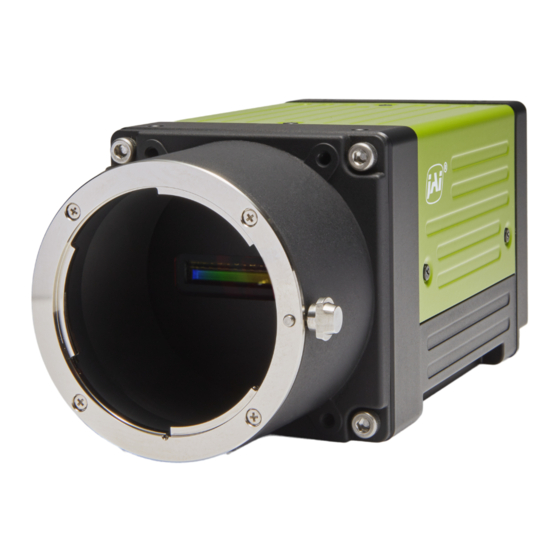
Page 7: Parts Identifications
SW-4000TL-SFP Parts Identification ② ⑤ ④ ③ ① ⑥ ⑥ ① Lens mount (M42-mount /F-mount) Mount a M42-mount lens, F-mount lens, etc. here. ❖ Before mounting a lens, be sure to refer to “Step 2:Connecting Devices” and confirm the precautions for attaching a lens and the supported lens types. - Page 8 SW-4000TL-SFP ② POWER/TRIG LED Indicates the power and trigger input status. LED status and camera status Light Status POWER/TRIG LED (Lit amber) Camera initializing. SFP+ module not inserted Not compatible SFP+ module inserted The Ethernet Link has not been established (Lit green) Camera in operation.
- Page 9 SW-4000TL-SFP ④ DC IN/TRIG connector(12-pin round) Connect the cable for a power supply (optional) or for DC IN / trigger IN here. Compatible connectors Camera side : HR10A-10R-12PB(71)(Hirose Electric or equivalent ) Cable side : HR-10A-10P-12S (plug) (Hirose Electric or equivalent )...
- Page 10 SW-4000TL-SFP Recommended external input circuit diagram (reference example) User side JAI Camera side CAMERA User side side Caution About Opto In.Check the recommended external input circuit diagram (reference example) and connect correctly. If you connect Opto In 1 and Opto In 2 in reverse, camera may be damaged.
-
Page 11: Preparation
When using the camera for the first time, install the software for configuring and controlling the camera (eBUS SDK for JAI) on the computer. ❖ When you install eBUS SDK for JAI, eBUS SDK for JAI player will also be installed. Download the eBUS SDK for JAI from the JAI website. -
Page 12: Step 2:Connecting Devices
SW-4000TL-SFP Step 2: Connecting Devices ⑤ DC IN/trigger IN connection cable ⑥ AC Adapter (not supplied) AC Adapter ①Lens Camera body ③ SFP+ module ④ Fiber optic cable ② Direct connection Switching hub ① Lens ・Attach an M42-mount lens or F-mount lens. These with lens mount protrusions of 13mm or less can be attached. - Page 13 SW-4000TL-SFP ③ SFP+ module Check the operation manual of the SFP+ module to be used, and attach it or remove it from the camera. The SFP+ module can be attached to and removed from the camera only when the camera is turned off.
-
Page 14: Step 3:Verifying Camera Operation
Verifying the Connection between the Camera and PC Verify whether the camera is properly recognized via Control Tool. Connecting the Camera to Control Tool Startup eBUS Player for JAI eBUS Player for eBUS Player for JAI startup screen appears. — 14 —... - Page 15 SW-4000TL-SFP Select the camera you want to configure. Push Select / Connect button The connected camera is listed. Please select one camera. — 15 —...
- Page 16 SW-4000TL-SFP Check that the settings of the selected camera are displayed. Push the Device control button. The screen shown below will be displayed. In this window you can adjust various settings of the camera. This completes the procedure for verifying whether the camera is properly recognized and whether control and settings configuration are possible.
-
Page 17: Step 5:Changing The Camera Settings
SW-4000TL-SFP Step 5 Configuring Basic Settings for the Camera Caution Because this camera automatically performs several correction functions at startup, the first three lines captured after powering on or resetting the camera will contain incorrect data. To ensure accuracy, you should not use the first three lines acquired after any power-up or reset. - Page 18 SW-4000TL-SFP Set [Exposure Mode] to [Trigger Width] . If necessary, change the [Trigger Source] and [Trigger Activation] settings. ■Control Without External Triggers When Controlling the Exposure Time Using Specified Exposure Times Configure the settings as follows. Item Setting value / selectable range...
-
Page 19: Step 6:Adjusting The Image Quality
SW-4000TL-SFP Step 6: Adjusting the Image Quality Display the camera image and adjust the image quality. Displaying the Image Display the image captured by the camera. When you push [Play] button, the camera image appears in right area. Note It is recommended to set [GevGVCPPendingAck] in [TransportLayerControl] to True. - Page 20 SW-4000TL-SFP To maximize the performance of the camera, configure its basic function in the following order. Configure the line rate. ◇ For details on this setting, “Variable Line Rate”. Configure the exposure time. ◇ For details on this setting, “Electronic Shutter” .
-
Page 21: Step 7:Saving The Settings
SW-4000TL-SFP Step 7: Saving the Settings The setting values configured in the player (eBUS SDK for JAI) will be deleted when the camera is turned off. By saving current setting values to user memory, you can load and recall them whenever necessary. You can save up to three sets of user settings in the camera. -
Page 22: Main Functions
SW-4000TL-SFP Main Functions Valid Input / Output Combinations The following signals can be used as sources for each output destination (Trigger Selector, Line Selector, Pulse Generator Selector). You can also connect two different sources to NAND paths in the GPIO and reuse the signal generated there as a source for a different selector. -
Page 23: Gpio(Digital Input/Output Settings)
• When using external signals or the signals of each GPIO module as trigger signals: Select in [Trigger Selector] > [Trigger Source]. • When selecting the signals to use for external outputs: Select in [Line Selector] > [Line Source]. Pixel Format The SW-4000TL-SFP supports five output formats. RGB8 RGB10V1Packed RGB10p32 YUV422_8_UYVY YUV422_8 —... -
Page 24: Exposuremode
SW-4000TL-SFP Exposure Mode The following operation modes are available on the camera. Operation mode Exposure Mode Trigger Mode Timed Trigger Width Image Output Timing ■ Trigger Control In this camera, the following control is performed by the external trigger signal. - Page 25 SW-4000TL-SFP ■ When [Exposure Mode] is [OFF] Trigger Exposure Active Readout Delay Time from Period from Trigger to Expousre Acrive Exposure Active Trigger Period[A] LVAL Active[D] Pixel Format Width Exposure Non Active[B2] Falling (μs) (μs) Active[B1] (μs) to LVAL rising[C] (μs)
- Page 26 SW-4000TL-SFP ■ When [Exposure Mode] is [Timed] Trigger Exposure Active Readout Delay Time from Period from Trigger Rising to Exposure Active Trigger Period[A] LVAL Active[D] Pixel Format Width Exposure Active Falling (μs) (μs) Rising[B] to LVAL rising[C] (μs) (μs) 4096 15.02...
- Page 27 SW-4000TL-SFP ■ When [Exposure Mode] is [Trigger Width] Trigger Exposure Active Readout Delay Time from Period from Delay Time from Trigger Rising to Exposure Active Trigger Falling to Trigger Period[A] LVAL Active[D] Pixel Format Width Exposure Active Falling Exposure Active (μs)
-
Page 28: Pixel Sensitivity Correction
SW-4000TL-SFP Pixel Sensitivity Correction Correct variations between the sensor’s pixels. Calibration must be performed within the camera and correction data must be created beforehand. DSNU (PixelBlackCorrect) / PRNU (PixelGainCorrect) can be reduced using that correction data. We recommend performing calibration and creating correction data whenever the line rate setting or Analog base gain setting or vertical binning setting are changed significantly. -
Page 29: Gain Control
SW-4000TL-SFP Gain Control The following gain functions are available on the camera. • Analog base gain • Digital gain ■ Analog base gain Analog base gain (ABG) is gain that is performed to the analog video signal output from the sensor. -
Page 30: Lookup Table (Lut)
SW-4000TL-SFP Lookup Table(LUT) The LUT function is used to generate a non-linear mapping between signal values captured on the sensor and those that are output from the camera. You can specify the output curve using 257 setting points (indexes). ■ To use the LUT function Configure the settings as follows. -
Page 31: Gamma Function
SW-4000TL-SFP Gamma Function The gamma function corrects the output signals from the camera beforehand (reverse correction), taking into consideration the light-emitting properties of the monitor display. As the light-emitting properties of the monitor are not linear, the entire image may be darker or the gradation in the dark areas may be less noticeable when camera outputs are displayed without processing. -
Page 32: Shadingcorrection
SW-4000TL-SFP Shading Correction The shading correction is a function that corrects non-uniformity (i.e., shading) in the amount of light generated by the lens and lighting equipment. The following shading correction modes are available on the camera。 ■ Flat shading correction Correct so that the part with the highest luminance level in the screen is taken as the reference and the other part is adjusted to this luminance level. -
Page 33: Variable Line Rate
SW-4000TL-SFP Variable Line Rate You can set the line rate to 1L or more. This function can be used to match the scanning speed of the camera to the feeding speed of the object or to lengthen the accumulation time to increase sensitivity. -
Page 34: Color Space Conversion
Default Caution If you set the color space to XYZ or HSI, eBUS Player for JAI will not display the images captured by the camera properly. To display them properly, XYZ- or HSI-compatible image processing must be performed on the computer side. -
Page 35: Counter And Timer Control Function
SW-4000TL-SFP Counter And Timer Control Function This camera supports only the counter function. The counter function counts up change points in the camera’s internal signals using the camera’s internal counter, and reads that information from the host side. This function is useful for verifying error conditions via the count value using internal camera operations. - Page 36 SW-4000TL-SFP ■ Internal camera blocks Counter0 Counter Event detection Line Trigger At event occurrence or count up Counter1 Counter Event detection Line Start At event occurrence or count up Counter2 Counter Event detection Exposure Start At event occurrence or count up ・...
-
Page 37: Tilted View Correction And Chromatic Aberration Correction
SW-4000TL-SFP Tilted View Correction and Chromatic Aberration Correction This camera features a tilted view correction function. The G channel, B channel, and R channel are positioned in that order on the sensor used on this camera. The G channel and R channel are corrected using the B channel in the middle as a reference. -
Page 38: Connecting Rotary Encoders
SW-4000TL-SFP Connecting Rotary Encoders This camera can generate trigger signals or detect the scanning direction of the subject in response to signals output from the rotary encoder. ■ Adjustment procedure Input the two signals (phase A and phase B) from the rotary encoder. -
Page 39: Frame Start Trigger
SW-4000TL-SFP Frame Start Trigger In this camera, Data Leader and Data Trailer are added every frame. The number of lines of one frame is set by Offset Y, Height of [Image Format Control]. Offset Y’s setting range is 0 to 4096. -
Page 40: Binning Function
SW-4000TL-SFP Binning Function The binning function allows you to combine the signal values of clusters of adjacent pixels to create improved virtual pixels. Using the function results in images with lower pixel resolution and higher sensitivity. This camera performs vertical binning via digital addition in the sensor. -
Page 41: Chunk Data Function
SW-4000TL-SFP Chunk Data Function The Chunk Data function adds camera configuration information to the image data that is output from the camera. Embedding camera configuration information in the image data allows you to use the serial number of the camera as a search key and find specific image data from among large volumes of image data. -
Page 42: Event Control Function
SW-4000TL-SFP Event Control Function The Event Control Function is a function that outputs a signal change point inside the camera as information indicative of an event occurrence (event message) by using GVCP (GigE Vision Control Protocol). ■ Flow from detecting an event to sending an event message... -
Page 43: Action Control Function
SW-4000TL-SFP Action Control Function The Action Control Function is a function that executes the pre-configured action when the camera receives action commands. Action commands can send both unicast and broadcast messages and give instructions for actions to multiple cameras simultaneously by broadcasting them. -
Page 44: Layout Of Pixels
Select the target to apply the filter from [Median Filter Selector] or [FIR Filter Selector] of [JAI Custom Control Pixel Correction] from Red, Green, Blue and set the [Median Filter Mode] or [FIR Filter Mode]. -
Page 45: Setting List
SW-4000TL-SFP Setting List Feature Properties Item Setting range Default value Description a) Device Control Display/configure information related to the device. Device Vendor Name ー "JAI Corporation" Display the manufacturer name. Device Model Name ー SW-4000TL-SFP Display the model name. Device Manufacturer Info ー... - Page 46 SW-4000TL-SFP Item Setting range Default value Description b) ImageFormatControl Configure image format settings. WidthMax ー 4096 Display the maximum image width. HeightMax ー 4096 Display the maximum image height. Width BinningHorizontal 1: 4096 Set the image width. 16〜4096 step 16 BinningHorizontal 2: 8〜2048 step 8...
- Page 47 SW-4000TL-SFP Item Setting range Default value Description d) Analog Control Configure analog control settings. IndividualGainMode Off, On In IndividualGainMode, R, G, B can be configured individually for the entire gain adjustment range of the sensor. GainSelector ー ー Select the gain to configure.
- Page 48 SW-4000TL-SFP Item Setting range Default value Description g) Digital I/O control Configure settings for digital input/output. Line Selector Line1 (TTL Out 1), ー Select the input/output to configure. Line4 (TTL In 1), Line5 (Opt In 1), Line8 (TTL Out 2),...
- Page 49 SW-4000TL-SFP Item Setting range Default value Description i) EncoderControl Configure settings for encoder control. EncoderSourceA Off, Select where to input the signal from the rotary encoder. Line4 (TTL In 1), Line5 (Opt In 1), Line10 (TTL In 2), Line13 (TTL In 3)
- Page 50 SW-4000TL-SFP Item Setting range Default value Description l) Event Control Event Selector ー ー Select the event to send the event message. [setting range] AcquisitionStart, AcquisitionEnd, FrameStart, FrameEnd, LineStart, LineEnd, ExposureRedStart, ExposureRedEnd, ExposureGreenStart, ExposureGreenEnd, ExposureBlueStart, ExposureBlueEnd, Line1RisingEdge, Line1FallingEdge, Line4RisingEdge, Line4FallingEdge,...
- Page 51 SW-4000TL-SFP Event Line4 Falling Edge Data ー ー When the event [Line4FallingEdge]occurs, the following three data can be checked. Event Line4 Falling Edge ー ー Display the EventID(0x931B). Event Line4 Falling EdgeTimestamp ー ー Displays the Timestamp value when an event occurs.
- Page 52 SW-4000TL-SFP Item Setting range Default value Description n) Chunk Data Control Configure chunk control settings. Chunk Mode Active True, False False Set whether to enable ChunkData Chunk Selector ー OffsetX Select the chunk settings. [Setting range] OffsetX, OffsetY, Width, Height, Binning Horizonal, Sensor Binning Vertical...
- Page 53 SW-4000TL-SFP Item Setting range Default value Description o) Transport Layer Control Display information on transport layer control. PlayloadSize (B) ー 12288 Display the payload size. GevSupportedOptionSelector Select the supported options for GigEVision. [Setting range] SingleLink, MultiLink, StaticLAG, DynamicLAG, PAUSEFrameReception, PAUSEFrameGeneration,...
- Page 54 SW-4000TL-SFP Item Setting range Default value Description p) PulseGenerator Configure pulse generator settings. ClockPreScaler 1〜4096 Set the division value for the prescaler (12 bit) using PixelClock as the base clock. PulseGeneratorClock (MHz) 0.024414 〜 100 Set the clock used for the pulse generator.
- Page 55 SW-4000TL-SFP Item Setting range Default value Description r) Correction Correct variations due to sensors and lenses. Pixel Black Correction Mode Off, Default, User1, Default Select the user area to which to save the black level correction value. User2, User3 Calibrate Pixel Black Correction ー...
-
Page 56: Miscellaneous
SW-4000TL-SFP Miscellaneous Troubleshooting Check the following before requesting help. If the problem persists, contact your local JAI distributor. ■ Power supply and connections Problem Cause and solution The POWER/TRIG LED remains lit amber and Camera initialization may not be complete does not turn green, even after power is due to lack of a network connection. -
Page 57: Specifications
SW-4000TL-SFP Specifications Item SW-4000TL-SFP 4K high speed trilinear CMOS image sensor Image sensor Effective pixels 3×4096 pixel (R, G, B) pixel size 7.5 μ m × 7.5 μ m Synchronization Internal Communication Interface 10GBASE-R Line rate RGB8 66Hz* 〜66kHz ( 0.1Hz/step ) - Page 58 SW-4000TL-SFP 1 Pixel sensitivity correction: Pixel correction (DSNU, PRNU) 2 Shading correction: ColorShading, FlatShading Image porcessing 3 LUT: OFF: γ=1.0, ON: 257 points can be set 4 Gamma: 0.45, 0.5, 0.55, 0.6, 0.65, 0.75, 0.8, 0.9, 1.0 (9 steps available) PRNU Post-correction: Within ±1% (during 100% output)
-
Page 59: Spectral Response
SW-4000TL-SFP Spectral Response Wave length (nm) — 59 —... -
Page 60: Dimensions
SW-4000TL-SFP Dimensions F mount (SW-4000TL-SFP-F) Dimenstional tolerance: ± 0.3mm Unit: mm — 60 —... - Page 61 SW-4000TL-SFP M42 mount (SW-4000TL-SFP-M42) Dimenstional tolerance: ± 0.3mm Unit: mm — 61 —...
-
Page 62: Comparison Of The Decibel Display And Multiplier Display
SW-4000TL-SFP Comparison of the Decibel Display and Multiplier Display Decibels[db] Multipliers[x] Remarks 0.501 0.562 0.631 0.708 0.794 0.891 1.122 1.259 1.413 1.585 1.778 1.995 2.239 2.512 2.818 3.162 3.548 3.981 4.467 5.012 5.623 6.31 7.079 7.943 8.913 11.22 12.589 14.125 15.849... -
Page 63: User's Record
Camera type: SW-4000TL-SFP Revision: …………… Serial No: …………… Firmware version: …………… For camera revision history, please contact your local JAI distributor. Trademarks • Microsoft and Windows are trademarks or registered trademarks of Microsoft Corporation in the United States and other countries. -
Page 64: Index
SW-4000TL-SFP Index 12-pin round LAN Cable Lens Acquisition Lens mount Adjusting the Black Level Lookup Table Adjusting the Gain Binning Function Network card Black level Output format Camera locking screw holes Chunk Data Function Color Space Conversion Parts Identification Color Transformation Control... -
Page 65: Revision History
SW-4000TL-SFP Revision history Revision Date Changes First version Jun. 2019 Oct. 2020 Add Noise reduction digital filter function, etc. Nov. 2020 China RoHS, etc. — 65 —...
Need help?
Do you have a question about the SW-4000TL-SFP and is the answer not in the manual?
Questions and answers