
Related Manuals for JAI SW-2000M-CL-65


Summary of Contents for JAI SW-2000M-CL-65
- Page 1 SW-2000M-CL-65 User's Manual SW-2000M-CL-65 CMOS High Speed Monochrome Line Scan Camera Document Version: 1.1 Date: 28 August 2014 File: Manual_SW-2000M-CL-65_First_Release_1-1.docx 1...
- Page 2 JAI Oy, Finland and may only be used by the purchasers of the product. JAI Oy, Finland makes no warranty for the use of its product and assumes no responsibility for any errors which may appear or for damages resulting from the use of the information contained herein.
-
Page 3: Table Of Contents
SW-2000M-CL-65 Contents – General ....................... 5 Camera nomenclature ................5 Main features ....................5 Connectors and mounting .................. 6 Main unit ....................6 Rear panel and indicators ................7 Input and output .................... 8 M8 connector for power supply ..............8... - Page 4 FIRMWARE UPDATE – initiate the MCU update ..........37 Summary of commands ..................38 Software tools for camera communications ............41 JAI SweepConf ..................41 JAI Sweep Ethernet Tool ................42 Internal web server ................. 44 10 External dimensions ..................45 11 Specifications ....................46 11.1...
-
Page 5: General
SW-2000M-CL-65 1 General The JAI Sweep Series SW-2000M-CL-65 is a CMOS line scan camera based on a custom-made 2048 pixel imager with large square pixels of 20 µm for high responsivity. It operates at a rate of up to 80,000 scans per second. -
Page 6: Connectors And Mounting
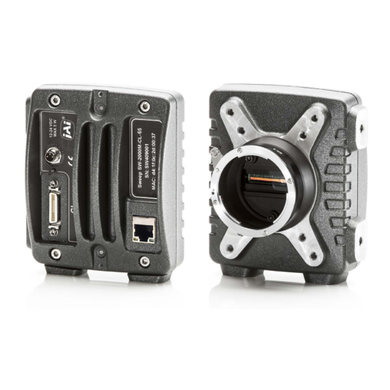
SW-2000M-CL-65 3 Connectors and mounting 3.1 Main unit 6 6 6 6 Fig. 1. Location of external features Camera Link Base Configuration connector LED indicator M8 connector for supply voltage (+12 to +24 V DC) Ethernet connector Lens mount: Nikon F-Mount Mounting holes: all 12 pcs. -
Page 7: Rear Panel And Indicators
SW-2000M-CL-65 3.2 Rear panel and indicators Fig.2. Rear panel Status indicator A multi-colour LED with the following functions: Green (steady) Normal operation Green (flashing slowly) Busy, performing a time consuming operation like FFC calibration. Green (flashing rapidly) Performing firmware update or waiting for a firmware update to start. -
Page 8: Input And Output
SW-2000M-CL-65 4 Input and output 4.1 M8 connector for power supply Camera side connector is an industry standard 3-pin M8 male connector. Use any compatible 3-pin M8 female connector on the cable side. Fig. 3. Power supply connector (viewed looking into the camera) Pin No. -
Page 9: Camera Link Output Modes
SW-2000M-CL-65 4.3 Camera Link output modes All these modes are presented in the standard according to the names shown on the first line. This table shows the use of these configurations to implement various data output modes. Bit depths of 8, 10, and 12 are supported, where MSB is labeled as M11 and LSB as M0. Camera operates internally with more than 12 bits. -
Page 10: Operation And Functions
5.1 Introduction 5.1.1 Image sensor The SW-2000M-CL-65 is built around a high performance CMOS line scan image sensor, which converts the light collected by each pixel into electrical charge. The amount of charge generated in each of the individual pixels is basically directly proportional to the amount of light they receive. -
Page 11: Image Processing
SW-2000M-CL-65 5.1.2 Image processing The output data from the imager is buffered for further processing to be then finally sent out of the camera via the Camera Link interface. The processing chain is controlled by user accessible commands. The DSNU corrector is calibrated individually for each camera at the factory and always in use with fixed settings. -
Page 12: Operating Modes
5.5 Test Pattern Generator The SW-2000M-CL-65 can send out five, defined test patterns instead of the real imaged lines for purposes like interfacing and problem analysis. The patterns replace the image data and can thus be used also to test the following blocks. -
Page 13: Region Of Interest, Roi
Shading correction is replaced by FFC, which operates assuming a fixed dark reference level and includes the PRNU correction. The FFC unit of SW-2000M-CL-65 offers the possibility to scale the pixel values by factors that are calculated by imaging a calibration target in order to produce a uniform (flat) response under the same conditions as where the calibration routine was run. -
Page 14: Camera Link Interface
SW-2000M-CL-65 5.10 Camera Link interface One Camera Link connector is available to connect standard Base Configuration interface devices (frame grabber boards, etc.) to receive image data, to control the scan rate and exposure of the camera, as well as to communicate via the Camera Link serial channel. -
Page 15: Firmware Updates
SW-2000M-CL-65 5.12 Firmware updates It is possible to update or change the camera firmware without opening the housing. New code is loaded in via the Ethernet port and with help of web browser user interface. There are two kinds of firmware updates: MCU and FPGA. The MCU (microcontroller unit) updates affect the user interface and high level features of the camera, while the FPGA (field-programmable gate array) updates provide enhancements for low level or hardware related functions. -
Page 16: Fpga Firmware Update
SW-2000M-CL-65 5.12.2 FPGA firmware update 1. Make sure you have the correct file (.rbf) for the camera model and the existing configuration available. 2. Make sure you have a working communication via the Ethernet port. 3. Make sure you have a compatible web browser and can access the main page (http://10.10.10.10) already before initiating this update. -
Page 17: Command Line Interface
Connect the camera to a local area network using a twisted-pair cable. A shielded cable of category 5 or higher is recommended. • Open a Telnet client on the computer. Two options are available from JAI. Please refer chapter 9 of this document. Also free or commercial Telnet clients can be downloaded from various internet sites. -
Page 18: Command Format
SW-2000M-CL-65 6.4 Command Format The following notation is used for describing the command syntax: • BOLDFACE indicates the fixed command word that must be typed as it is • | A vertical line delimits alternative forms of a command •... -
Page 19: Description Of Commands
SW-2000M-CL-65 7 Description of commands The commands can be divided into four groups: Group A: General settings MODE for selecting operating mode after boot-up. NET for network settings for the Ethernet command communication. NET settings are saved automatically. CS SAVE, LOAD, SAVE2, LOAD2 and FACTORY RESET for saving, loading or restoring the settings of group B and C. - Page 20 SW-2000M-CL-65 The four groups will be described in detail in the following sections. Most commands display help on how to use it if a question mark is added after the command, and current status of the function if the command is entered as such with no parameters.
-
Page 21: Group A: General Settings
SW-2000M-CL-65 Group A: General settings MODE select camera operating mode 7.1.1 – The command MODE selects the operating mode that will be entered when the camera is rebooted. Command Description MODE ? Returns the MODE setting syntax and a list of available modes to select from. - Page 22 SW-2000M-CL-65 NET MASK set the IP subnet mask 7.1.2.2 – This command sets the IP subnet mask of the camera. The command has no effect in case of using dynamic IP addressing. Command Description NET MASK ? Returns the syntax for setting NET MASK.
-
Page 23: Cl Serial - Sets The Baud Rate
SW-2000M-CL-65 CL SERIAL sets the baud rate 7.1.3 – The baud rate of the serial communications channel via the Camera Link cable has the default value of 9600 bps, but can be set for higher speed. Please note that as the new value takes effect immediately, the response to this command will not be received correctly, if the command was given via Camera Link. -
Page 24: Saving And Restoring The Capture Settings
SW-2000M-CL-65 7.1.4 Saving and restoring the capture settings Command Description CS ? List of available Capture Settings group commands. Returns the present Capture Settings. CS SAVE Saves the present Capture Settings to the first memory location. Loaded during reboot and power-up. - Page 25 SW-2000M-CL-65 CS SAVE2 save settings (2 set) 7.1.4.4 – This command stores all the above-mentioned settings to the second location in non-volatile memory. CS LOAD2 load settings (2 set) 7.1.4.5 – This command restores all the above-mentioned settings from the second memory location of the non-volatile memory.
-
Page 26: Group B: Commands Affecting Exposure
SW-2000M-CL-65 Group B: Commands affecting exposure SENSOR 7.2.1 – selects the sensor mode The sensor has two possibilities of collecting the light generated charge. The default setting uses the larger well size for a wider dynamic range and a better signal to noise ratio, which results in more valid bits. -
Page 27: Line Ctrl - Exposure Control
SW-2000M-CL-65 LINE CTRL - Exposure Control 7.2.3 The camera has three exposure control modes: internal, external and mixed, which is a combined mode of the first two. The start and length of each line, as well as the time that the light is collected within each line period, follow the same principles regardless of the selected mode. - Page 28 SW-2000M-CL-65 time as the line period ends. The Internal exposure mode cannot be synchronized to an external event. If external synchronization is needed then External or Mixed mode must be selected for Exposure Control. 7.2.3.2 External exposure control (command: LINE CTRL EXT) The line period and integration time are controlled externally by the CC1 and CC2 input signals at the Camera Link connector.
- Page 29 SW-2000M-CL-65 7.2.3.3 Mixed mode exposure control (command: LINE CTRL MIX) The line period is now the time between two consecutive rising edges of the CC1 input signal at the Camera Link connector. The integration time is controlled internally by the command LINE IT. The syntax for LINE IT gives the ability to set the integration time in microseconds or in percentage of maximum possible integration time.
-
Page 30: Line It - Integration Time
SW-2000M-CL-65 LINE IT integration time 7.2.4 This command is used to control the integration time (effective exposure time) for each line. The timing can be specified either as an absolute time in microseconds, or as percentage of the line period. The integration time given as percentage of the line interval is recalculated automatically when the line rate changes. -
Page 31: Ffc - Flat Field Correction
SW-2000M-CL-65 the full scale. The offset is always entered as a 12-bit number, which means that if you have set the camera for one of the 8-bit output modes, you should multiply the intended offset shift by 16 to get the offset for this command. -
Page 32: Group C: Commands Affecting Image Output Format
SW-2000M-CL-65 Group C: Commands affecting image output format CL MODE 7.3.1 - Camera Link mode This command selects the output mode for the final image data. Command Description CL MODE ? Returns the command syntax CL MODE Returns the present CL MODE setting CL MODE SINGLE 8 8 bits per pixel. -
Page 33: Roi - Region Of Interest
SW-2000M-CL-65 7.3.4 – region of interest This command can be used to select only specific sections of each line to be sent out. Up to four regions can be defined. The selected parts of the line will be combined together to make one, shorter line. -
Page 34: Binning - Paring Of Pixels
SW-2000M-CL-65 BINNING 7.3.5 – paring of pixels Binning mode combines adjacent pixels as pairs either to double the response by summing the two original values or to decrease noise by taking the average of the two values. ROI operation may be in use prior to this. Binning decreases the number of output values by factor of two. -
Page 35: Group D: Utilities
SW-2000M-CL-65 Group D: Utilities HELP ‘?’ list of commands 7.4.1 – STATUS 7.4.2 camera information and settings This command displays version information of various components of the camera. The command also returns camera model number, MAC address and serial number. - Page 36 SW-2000M-CL-65 Command Description TEST OFF No test pattern. Image data originates from the sensor (default). TEST P1 Sawtooth: horizontal rising ramps from 0 to maximum. All lines are equal. In case of 8 bit output, the line graph includes 8 such periods, when advancing across the 2K pixels.
-
Page 37: Reboot - Restart The Camera
SW-2000M-CL-65 TEST P5 A combination of rising ramps in both directions. Horizontally the length of the sequence varies at the same phase as the lowest value of the pattern changes from line to line. Vertically the lowest value of each line specific pattern varies from line to line as rising ramps from zero to maximum, similarly to how the pattern P3 behaves on its own. -
Page 38: Summary Of Commands
SW-2000M-CL-65 8 Summary of commands A – General settings. Command Function Command Format Parameter Remarks Camera operating fundamental settings, MODE <file name> mode reboot required 2 Network settings NET IP <address> xxx.xxx.xxx.xxx static, DHCP off 3 set IP address NET IP AUTO... - Page 39 SW-2000M-CL-65 B – Commands affecting exposure Command Function Command Format Parameter Remarks Larger capacity, Sensor operating DYNAMIC lower noise. SENSOR mode RESPONSIVE Smaller capacity, higher responsivity. Minimum depends Line interval in µs, from on CL mode and Line interval LINE PERIOD <time>...
- Page 40 SW-2000M-CL-65 C – Commands affecting image output format Command Function Command Format Parameter Remarks SINGLE 8 8 bits, 1 pixel/clock SINGLE 10 10 bits, 1 pixel/clock SINGLE 12 12 bits, 1 pixel/clock 1 Camera Link mode CL MODE <mode> DUAL 8...
-
Page 41: Software Tools For Camera Communications
Default IP address is 10.10.10.10. Telnet Port is number 23. JAI provides two control tools as Windows software, as well as web browser access. JAI SweepConf The SweepConf offers a graphical user interface with sliders and pop down menus for the most common functions as well as a telnet terminal. -
Page 42: Jai Sweep Ethernet Tool
SW-2000M-CL-65 JAI Sweep Ethernet Tool The Sweep Ethernet Tool is a telnet terminal program with possibility to run scripts and to display single line graphs (average of 32 lines). Fig.8. Front page after initialization and the help command. - Page 43 SW-2000M-CL-65 Fig.9. Line graph display with no frame grabber. Test pattern 2.
-
Page 44: Internal Web Server
SW-2000M-CL-65 Internal web server The internal Web server can be accessed by standard web browsers at http://10.10.10.10/. It offers some documents for download and is used while updating camera firmware. Fig.10. Home page. -
Page 45: External Dimensions
SW-2000M-CL-65 External dimensions Fig.11. External dimensions in mm. -
Page 46: Specifications
SW-2000M-CL-65 Specifications 11.1 Operating range Parameter Min Typical Unit Notes 2048 CMOS (custom), line scan Number of pixels Pixel size 20.0 20.0 µm square Fill factor Length of the imager 40.96 40.96 Pixel clock adjustable Line scan period 15.3 100k µs... -
Page 47: Common Properties
SW-2000M-CL-65 Common properties 11.2 Notes Property External (external trigger, external shutter) Operation modes Internal (internal trigger, internal shutter) Mixed (external trigger, internal shutter) Data interface Camera Link Base Configuration 8, 10 or 12 bits x1 Output modes 8, 10 or 12 bits x2... -
Page 48: Spectral Sensitivity
SW-2000M-CL-65 11.4 Spectral sensitivity 80,0 70,0 60,0 50,0 40,0 30,0 20,0 10,0 350 400 450 500 550 600 650 700 750 800 850 900 950 1000 1050 1100 Wavelength (nm) (visible light is 390 to 750 nm) Fig. 12. Total spectral response (typical, without lens) -
Page 49: Change History
SW-2000M-CL-65 12 Change History Date Revision Changes 12 June 2014 First Release (1.0) 28 Aug 2014 First Release, rev. 1.1 (FCC, input voltage, CS commands, web server) - Page 50 Company and product names mentioned in this manual are trademarks or registered trademarks of their respective owners. JAI A-S cannot be held responsible for any technical or typographical errors and reserves the right to make changes to products and documentation without prior notification.
Need help?
Do you have a question about the SW-2000M-CL-65 and is the answer not in the manual?
Questions and answers