
Related Manuals for arcelik beko B7S


Summary of Contents for arcelik beko B7S
-
Page 1: Cover
B7S ( ANK )WASHING MACHINE SERVICE MANUEL SERVICE MANUEL NO:01 B7S (ANK) CONTROL SYSTEM (WASHING MACHINE SERVICE HANDBOOK Sensitivity: Public Sensitivity: Public... -
Page 2: Table Of Contents
B7S ( ANK )WASHING MACHINE SERVICE MANUEL 1. COVER……………………………………………………………………..……….…..1 CONTENS ………………………………………………………………..………..… . . COMPONENTS ....................3 ..........................3 3.1. ECHANICAL ARTS ........................ 3 3.2. HOCK BSORBER YSTEM 3.3..................3 LECTRONIC ONTROL AND ISUAL 3.4. ) ......................4 AFETY WITCH 3.5. -
Page 3: Components
B7S ( ANK )WASHING MACHINE SERVICE MANUEL 3. . COMPONENTS 3.1. Mechanical Parts All drums are made of a special plastic which is made of high-resistant plastic and reduces the level of the sound strength and does not have a oxidation problem. Drum cover which is used in the YOC series machines is also made of plastic and attached to the drum with special clips. -
Page 4: Safety Switch (Door Lock)
B7S ( ANK )WASHING MACHINE SERVICE MANUEL 3.4. Safety Switch (Door Lock) Picture 4.11 Safety key Normal Operation Voltage : 230V 50-60Hz Working Current : 16 A Working Environment Humidity: Rh 10- 95%Rh Work Environment Temperature: 5°C / 75°C Electrical Locking slide switching box hole... - Page 5 B7S ( ANK )WASHING MACHINE SERVICE MANUEL Sensitivity: Public Sensitivity: Public...
- Page 6 B7S ( ANK )WASHING MACHINE SERVICE MANUEL Picture 3.2 Dorr unlock arm Sensitivity: Public Sensitivity: Public...
-
Page 7: Wash Motor
B7S ( ANK )WASHING MACHINE SERVICE MANUEL 3.5. Wash Motor 3.5.1. Atlas Motor Picture 3.3 Motor (Atlas motor ve Vektör cart) Brushless motor is used. Motor stator consists of 3-phase coil and magnets are on the rotor. Rotor position is detected from askoll-type hall sensor, stator windings are enegized with the help of an inverter. -
Page 8: Heater
B7S ( ANK )WASHING MACHINE SERVICE MANUEL 3.6. Heater It is used to heat the water inside the drum. Since it is an electronically controlled machine, there is a double thermocouple at each of the heater inlets. When the heater operates dry, the overheated thermocouple open circuits the heater. Open circuited heater cannot be used again. -
Page 9: Drain Pump
B7S ( ANK )WASHING MACHINE SERVICE MANUEL 3.8. Drain Pump It is a synchronous motor equipped with a mono-phase bipolar magnet rotor. At the draining step, electronic control card is activated by the triac on it. It is protected by impedance for continuous operation and blocking situation of the rotor. -
Page 10: Water Level Sensor
B7S ( ANK )WASHING MACHINE SERVICE MANUEL Table 3.1 NTC values 3.10. Water Level Sensor An analog water level sensor which is fed by 5 V voltage is used. This sensor ensures that the water level is determined instantly with the frequency values which it generates against the pressure created. -
Page 11: Service Mode Steps
B7S ( ANK )WASHING MACHINE SERVICE MANUEL 4. Service Mode Steps: Warnings Service to be Condition for Passing to Mode Step Açıklama Realized status written on passing to next step next step display screen * In order to activate the components being controlled in each step of the service mode, the... - Page 12 B7S ( ANK )WASHING MACHINE SERVICE MANUEL the process of transmitting the motor parameters to the motor card is completed (approximately 7-8 seconds) and then passed to the next step if pressed on "start/pause" button. Can be pressed on the Software Software Pressed...
- Page 13 B7S ( ANK )WASHING MACHINE SERVICE MANUEL If the Water Level Value read from the Water Level Sensor is out of limits (if the Water Level Sensor socket is not properly connected or there is no contact), passed to the next step “7”. In this way, if there is no drum movement in step 6 and passed...
- Page 14 B7S ( ANK )WASHING MACHINE SERVICE MANUEL The level defined in this step is between Psafety level and Pdoor level. Prewash Valve is driven. * In products without FM, water intake is performed until pressed to the button. Pressed Prewash * In products with FM, Valve test water is taken for a period...
- Page 15 B7S ( ANK )WASHING MACHINE SERVICE MANUEL If the water level is less than "Psafety Hz" in terms of frequency value (if there is water above this level in terms of level), the heater is driven. If the water level is higher than 'Psafety Hz' in terms of frequency (if there is water below this level in...
- Page 16 B7S ( ANK )WASHING MACHINE SERVICE MANUEL completed even "Start / Pause" is pressed as long as the water level does not reach to "Psafety" If the start/pause button is pressed again after the end of the step, returns to the beginning of the service mode.
-
Page 17: Component Assembly / Disassembly
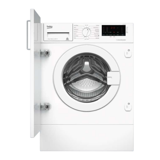
B7S ( ANK )WASHING MACHINE SERVICE MANUEL 5. COMPONENT ASSEMBLY / DISASSEMBLY Front view of the machine is given in the Picture 5.1. Picture 5.1 General appearance 5.1. Upper Table Assembly / Disassembly 7 sheet metal screws fixing the upper table to the body are removed. Upper table is removed by being lifted to backwards and then upwards. -
Page 18: Detergent Drawer Front Cover
B7S ( ANK )WASHING MACHINE SERVICE MANUEL Picture 5.3 Upper table Disassembly/Assembly 5.2. Detergent Drawer Front Cover Design of detergent box and drawer are new. It contains 4 parts for prewash powder detergent, main wash powder and liquid detergent, and softener. The drawer will be taken out by pulling it strongly. -
Page 19: Panel Assembly
B7S ( ANK )WASHING MACHINE SERVICE MANUEL Picture 5.5 Detergent drawer Detergent drawer is removed by pressing on the area shown with arrow on the siphon. 5.3. Panel Assembly Detergent drawer is removed. Picture 5.6 Panel Disassembly/Assembly Sensitivity: Public Sensitivity: Public... - Page 20 B7S ( ANK )WASHING MACHINE SERVICE MANUEL Picture 5.7 Panel Disassembly/Assembly Picture 5.8 Panel Disassembly/Assembly 2 pt screws which fix the panel to the panel reinforcement bracket and the detergent compartment and shown separately in the following pictures are removed. Tabs fixing the panel to the reinforcement bracket are released and the panel is detached from the reinforcement bracket.
-
Page 21: Program Control Card
B7S ( ANK )WASHING MACHINE SERVICE MANUEL Picture 5.10 Panel Disassembly/Assembly Picture 5.11 Panel Disassembly/Assembly Picture 5.12 Panel Disassembly/Assembly 5.4. Program Control Card Picture 5.13 Control card Disassembly/Assembly Sensitivity: Public Sensitivity: Public... - Page 22 B7S ( ANK )WASHING MACHINE SERVICE MANUEL Picture 5.14 Control card Disassembly/Assembly Picture 5.15 Control card Disassembly/Assembly Picture 5.16 Control card Disassembly/Assembly Sensitivity: Public Sensitivity: Public...
-
Page 23: Front Door Group Assembly/Disassembly
B7S ( ANK )WASHING MACHINE SERVICE MANUEL 5.5. Front Door Group Assembly/Disassembly Front door is opened. 2 screws of the hinge holder that serves as front door holder by the hinge are unscrewed and the holder is removed. Front door is separated from the hinge. 2 hinge screws fixing the hinge to the front door are removed and hinge is removed from the front door. -
Page 24: Front Wall Disassembly/Assembly
B7S ( ANK )WASHING MACHINE SERVICE MANUEL Picture 5.19 Front door disassembly /assembly 5.6. Front Wall Disassembly/Assembly Front door group is removed. Body bellows clamp fixing the drum bellows to the front door is removed by use of a special bellows clamp pliers. Door locking screws are removed. - Page 25 B7S ( ANK )WASHING MACHINE SERVICE MANUEL Picture 5.21 Front Wall Disassembly / Assembly Picture 5.22 Front Wall Disassembly / Assembly Sensitivity: Public Sensitivity: Public...
- Page 26 B7S ( ANK )WASHING MACHINE SERVICE MANUEL Picture 5.23 Front Wall Disassembly / Assembly Picture 5.24 Front Wall Disassembly / Assembly Sensitivity: Public Sensitivity: Public...
-
Page 27: Parasite Filter
B7S ( ANK )WASHING MACHINE SERVICE MANUEL 5.7. Parasite Filter Upper table is removed. Parasite Filter cable terminals are removed. 2 screws, at the back of the body, attaching the terminal group to the body are removed. M8 nut which attaches the parasite filter to the terminal group is held by double- ended wrench and the parasite filter is removed by turning manually. -
Page 28: Single Valve
B7S ( ANK )WASHING MACHINE SERVICE MANUEL 5.9. Single Valve Upper table is removed. Single valve cable terminals are removed. Single Valve Hose clamp is pulled back over the hose. Hose is ejected from the end on the valve. At the back of the body, the tab fixing the valve to the body is pushed inside with a screwdriver and the valve is turned towards left. -
Page 29: Safety Switch
B7S ( ANK )WASHING MACHINE SERVICE MANUEL 5.11. Safety Switch Door is opened by pulling from the handle. Drum bellows clamp fixing the drum bellows is removed. 2 screws fixing the safety switch to the front door are removed. Safety Switch cable ends are removed. Picture 5.29 Disassembly/assembly of safety switch 5.12. -
Page 30: Drain Pump Attachment / Detachment
B7S ( ANK )WASHING MACHINE SERVICE MANUEL 5.13. Drain Pump Attachment / Detachment Upper table is removed. Panel is removed. Front wall is removed. Screws on the body are removed. Picture 13.139. Clamp at the pump inlet of the discharge hose is pulled backwards. ... -
Page 31: Drum Bellows
B7S ( ANK )WASHING MACHINE SERVICE MANUEL 5.14. Drum Bellows Front wall is removed. Spiral spring connecting the bellows to the drum is removed. Bellows is pulled and removed manually from the front door. Picture 5.33 Disassembly/Assembly of Drum Bellows 5.15. -
Page 32: Polyv Belt
B7S ( ANK )WASHING MACHINE SERVICE MANUEL 5.17. Poly V Belt Rear cover is removed. Poly V belt is turned and removed from over the drum pulley. Pulley Poly V belt Picture 5.35 Disassembly/assembly Poly V Belt 5.18. Pulley Rear cover is removed. Poly V belt is turned and removed from over the pulley. -
Page 33: Power Cable
B7S ( ANK )WASHING MACHINE SERVICE MANUEL 5.20. Power Cable Cable Holder Screw is removed. Power Cord is removed with its terminals being detached from the parasite filter. Picture 5.37 Disassembly/assembly of Power Cable 5.21. Upper Counterweight Upper table is removed. Upper Counterweight is removed with its retaining bolts detached. -
Page 34: Lower Counterweight
B7S ( ANK )WASHING MACHINE SERVICE MANUEL 5.22. Lower Counterweight Front wall is removed. Lower Counterweight Retaining Bolts are removed. (When the upper and lower counterweights are assembled, torque value should be 2100 Ncm (-900 Tolerance). Picture 5.39 Disassembly/assembly of lower counterweight IMPORTANT: When the machine is required to be serviced by being tilted to the front, its transport safety bolts should be installed, if this is not necessary, lower counterweight bolts should not be fully removed. -
Page 35: Mounting The Cabinet Door
B7S ( ANK )WASHING MACHINE SERVICE MANUEL 5.24. - Mounting the cabinet door - Door of the cabinet may be attached to left or right depending on the preference. Mounting method of the cabinet door that opens leftward is explained below. The same mounting method applies for the right side. - Page 36 B7S ( ANK )WASHING MACHINE SERVICE MANUEL After mounting the cabinet door, the plastic magnet assembly will be fitted in the empty assembly housings on the front wall primarily by seating the tabs and by means of 1 screw. The same process will be repeated for the lower part. Picture 5.42 Picture 5.43 Picture 5.44...
-
Page 37: Cabinet Door Plate
B7S ( ANK )WASHING MACHINE SERVICE MANUEL 5.25. - Cabinet door plate - The cabinet door plate will be fixed onto the door of the cabinet by means of 2 fiberboard screws for each. Picture 5.45 Sensitivity: Public Sensitivity: Public... -
Page 38: Built-In Installation
B7S ( ANK )WASHING MACHINE SERVICE MANUEL 5.26. BUILT-IN INSTALLATION Sensitivity: Public Sensitivity: Public... - Page 39 B7S ( ANK )WASHING MACHINE SERVICE MANUEL Sensitivity: Public Sensitivity: Public...
- Page 40 B7S ( ANK )WASHING MACHINE SERVICE MANUEL Sensitivity: Public Sensitivity: Public...
- Page 41 B7S ( ANK )WASHING MACHINE SERVICE MANUEL Sensitivity: Public Sensitivity: Public...
- Page 42 B7S ( ANK )WASHING MACHINE SERVICE MANUEL Sensitivity: Public Sensitivity: Public...
- Page 43 B7S ( ANK )WASHING MACHINE SERVICE MANUEL Sensitivity: Public Sensitivity: Public...
- Page 44 B7S ( ANK )WASHING MACHINE SERVICE MANUEL Sensitivity: Public Sensitivity: Public...
- Page 45 B7S ( ANK )WASHING MACHINE SERVICE MANUEL Sensitivity: Public Sensitivity: Public...
- Page 46 B7S ( ANK )WASHING MACHINE SERVICE MANUEL Sensitivity: Public Sensitivity: Public...
-
Page 47: Plugged Hose Holder
B7S ( ANK )WASHING MACHINE SERVICE MANUEL 5.27. - Plugged hose holder Product does not contain kickplate. As a result, plugged hose holder and kickplate plastic plug are used for covering the slots. - Lid of the plugged hose holder will be opened by releasing it from its tab. Plug of the plugged hose will be pulled rightward to take it out of its housing. -
Page 48: Heightening Kit Assembly Guide
B7S ( ANK )WASHING MACHINE SERVICE MANUEL Built-in raising set consists of, 1 piece raising kit package cardboard 2 pcs profile 4 pcs welded nut (M6) 4 pcs plain washer (M10 DIN125) 4 pcs spring washer (M10 DIN127) 4 pcs hexagon head bolt (M10X25 DIN933) Assembly method for built-in raising set to product is described in Heightening Kit Assembly Guide. - Page 49 B7S ( ANK )WASHING MACHINE SERVICE MANUEL Picture 5.50 Sensitivity: Public Sensitivity: Public...
-
Page 50: Washing Machine With Rear Feet Adjustable From The Front Side
B7S ( ANK )WASHING MACHINE SERVICE MANUEL 5.30. Washing Machine with Rear Feet Adjustable from the Front Side Feet assembly of the washing machine with rear feet adjustable from the front side is designed for built-in washing machines can be used with built-in products only. - Page 51 B7S ( ANK )WASHING MACHINE SERVICE MANUEL ADJUSTABLE FEET MECHANISM RIGHT ASSEMBLY:LEFT ASSEMBLY: Picture 5.52 Mechanism specifications A new feet assembly has been created to adjust the rear feet. A wire assembly is used to adjust the rear feet assembly from the front side, and a gear assembly is used to pass the movement to the feet.
- Page 52 B7S ( ANK )WASHING MACHINE SERVICE MANUEL How to assemble and disassemble the adjustable feet assembly Picture 5.53 Picture 5.54 Use the screwdriver to fully connect the adjustable feet assembly to the feet area. Sensitivity: Public Sensitivity: Public...
- Page 53 B7S ( ANK )WASHING MACHINE SERVICE MANUEL Picture 5.55 Picture 5.56 Pass the mechanism through the kick plate hole on the front side. Fit the plastic centering part and seat it in place. Then, fit the mechanism to the feet mechanism as shown in the picture. Picture 5.57 Sensitivity: Public Sensitivity: Public...
- Page 54 B7S ( ANK )WASHING MACHINE SERVICE MANUEL Picture 5.58 Picture 5.59 Use 3x 9 PT screws to connect the mechanism onto the body as shown in the picture. Sensitivity: Public Sensitivity: Public...
- Page 55 B7S ( ANK )WASHING MACHINE SERVICE MANUEL Points to consider: 1- Views from the top and lower sides of the mechanism are given. When installing, you should make the connection so that the square view in the picture must always be on the top. BASE Picture 5.60 2- The large sponge on the Movement Wire must be behind the damper,...
-
Page 56: Motor Board Installation/Removal (Vector Board)
B7S ( ANK )WASHING MACHINE SERVICE MANUEL Picture 5.62 5.31. Motor Board Installation/Removal (Vector board) To remove the motor board, remove the rear cover of the body. Remove the 2 screws on the body and the tab of the board holder from the body. - Page 57 B7S ( ANK )WASHING MACHINE SERVICE MANUEL Loose the tabs to remove the cable assembly fishbone clamp to which the motor board holder is attached. Picture 5.65 Motor board assembly removal/removal Picture 5.66 Motor board assembly removal/removal Remove the hose that is found on the motor board.
- Page 58 B7S ( ANK )WASHING MACHINE SERVICE MANUEL Remove the cable sockets that are found on the motor board. To remove the board, free it from the tabs on the board holder. Picture 5.68 Motor board assembly removal/removal Picture 5.69 Motor board assembly removal/removal Picture 5.70 Motor board assembly removal/removal Sensitivity: Public Sensitivity: Public...
-
Page 59: Part List
B7S ( ANK )WASHING MACHINE SERVICE MANUEL 6. Part List SAP should be taken as a basis for the part list. 7. List of Figures and Pictures 3.1 E ARCD ......................... 3 İCTURE LECTRNİC CONTROL CARD 3.3 M ) ..................... 7 İCTURE OTOR TLAS MOTOR VE... - Page 60 B7S ( ANK )WASHING MACHINE SERVICE MANUEL 5.48 B ..........................47 ICTURE UİLT İN RAİSİNG SET 5.49 ................................48 ICTURE 5.50 ................................49 ICTURE 5.51 ................................50 ICTURE 5.52 ................................51 ICTURE 5.53 ................................52 ICTURE 5.54 ................................52 ICTURE 5.55 ................................
Need help?
Do you have a question about the beko B7S and is the answer not in the manual?
Questions and answers