
Related Manuals for Knick SensoGate WA131H


Summary of Contents for Knick SensoGate WA131H
- Page 1 SensoGate WA131H User Manual Retractable Fitting Read before installation. www.knick-international.com Keep for future use.
-
Page 2: Supplemental Directives
SensoGate WA131H Supplemental Directives READ AND SAVE THIS DOCUMENT FOR FUTURE REFERENCE. BEFORE ATTEMPTING TO ASSEMBLE, INSTALL, OPERATE OR MAINTAIN THE PRODUCT, PLEASE ENSURE A COMPLETE UNDERSTANDING OF THE INSTRUC- TIONS AND RISKS DESCRIBED HEREIN. ALWAYS OBSERVE ALL SAFETY INFORMATION. FAILURE TO COMPLY WITH INSTRUCTIONS IN THIS DOCUMENT COULD RESULT IN SERIOUS INJURY AND/OR PROPERTY DAMAGE. -
Page 3: Table Of Contents
SensoGate WA131H Table of Contents 1 Safety............................. 1.1 Intended Use ................................. 1.2 Personnel Requirements ........................... 1.3 Safeguards................................1.4 Residual Risks ................................ 1.5 Safety Accessories..............................1.6 Hazardous Substances ............................1.7 Operation in Explosive Atmospheres ......................1.7.1 Possible Ignition Hazards During Installation and Maintenance.......... - Page 4 6.3.5 Immersion Tube: Installation......................40 6.3.6 Calibration Chamber: Removal ......................41 6.3.7 Calibration Chamber: Installation..................... 42 6.3.8 Knick Repair Service ..........................42 7 Troubleshooting ........................... 43 7.1 Malfunction State: Retractable Fitting Does Not Fully Move to the SERVICE or PROCESS Limit Position.................................
-
Page 5: Safety
“operating company”) may be conducted, subject to the requirements set forth herein, by placing the product into the service position (SERVICE limit position). If the product is used with any product or part not authorized by Knick, the operating company assumes all risks and liabilities related thereto. -
Page 6: Safeguards
SensoGate WA131H 1.3 Safeguards Solid Electrolyte Sensor Dismount Guard For versions of SensoGate WA131H for solid electrolyte sensors, sensors can only be dismounted in the service position (SERVICE limit position). In the process position (PROCESS limit position), the sensor is in the protection sleeve (1) -
Page 7: Residual Risks
Movement of the sensor into the SERVICE/PROCESS limit positions is triggered on the SensoGate WA131H by the pressurization of the control or process air. Some versions of the SensoGate WA131H are screwed to process connections with a thread or secured with coupling nuts. Travel movements or process-related vibrations may cause the process connection to accidentally come loose from the process or a coupling nut. -
Page 8: Safety Accessories
SensoGate WA131H Operating companies operate the SensoGate WA131H without a retainer clamp or locking clamp at their own risk. In this case, the operating company must implement measures that exclude the possi- bility of accidental loosening of the coupling nut of the screw joint. -
Page 9: Operation In Explosive Atmospheres
• Non-metallic components are cleaned with a moist cloth only. Mechanically Generated Sparks Single impacts on metal parts or collisions between metal parts of the SensoGate WA131H-X are not a potential ignition source if the following conditions are met: • Possible impact velocity is less than 1 m/s. -
Page 10: Possible Ignition Hazards During Operation
1.8 Safety Training Upon request, Knick Elektronische Messgeräte GmbH & Co. KG will provide safety briefings and prod- uct training during initial commissioning of the product. More information is available from the rele- vant local contacts. -
Page 11: Product
• As applicable, supplementary datasheet for special versions 2.2 Product Identification The various versions of the SensoGate WA131H product are coded in a model designation. The model designation is stated on the nameplate, the delivery note, and the product packaging. -
Page 12: Product Code
SensoGate WA131H 2.2.2 Product Code Basic unit with pneumatic drive unit, stainless steel, hygienic WA131H – _ _ _ _ _ _ _ _ _ _ – _ _ _ ATEX Zone 0 – Explosion protection Without – Sensor Ø12 mm with PG13.5 –... - Page 13 SensoGate WA131H Basic unit with pneumatic drive unit, stainless steel, hygienic WA131H – _ _ _ _ _ _ _ _ _ _ – _ _ _ SensoLock Without 0 – With 1 – Special version Without – 0 0 0 Equipment with special grease (provided by customer) –...
-
Page 14: Nameplates
SensoGate WA131H 2.3 Nameplates The SensoGate WA131H is identified by nameplates on the drive unit and the process unit. The infor- mation provided on the nameplates varies according to the version of the SensoGate WA131H. Nameplate, Version Without Ex Approval Note: The figure shows a nameplate for the SensoGate WA131H-N version by way of example. - Page 15 SensoGate WA131H Nameplate, Version With Ex Approval Note: The figure shows a nameplate for the SensoGate WA131H-X version by way of example. WA131H xxxxxxx / xxxx WA131H xxxxxxx / xxxx Drive unit nameplate 10 Serial number/year and week of production...
-
Page 16: Symbols And Markings
Permissible Changes, p. 19 ➜ The process connection is used to fasten the SensoGate WA131H to the process port. The pneumatically operated drive unit moves the SensoGate WA131H into the service position (SERVICE limit position) or the process position (PROCESS limit position). -
Page 17: Retractable Fitting
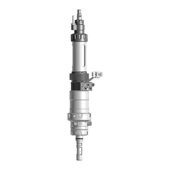
SensoGate WA131H 2.5.1 Retractable Fitting Note: The figure shows an example version of the SensoGate. Product Code, p. 12 ➜ Drive unit Outlet port Process unit Calibration chamber Sensor holder 10 Process connection Fixing bracket with grounding connection 11 Immersion tube... -
Page 18: Drives And Sensor Holders
SensoGate WA131H 2.5.2 Drives and Sensor Holders Note: The figure shows a selection from the product line. Product Code, p. 12 ➜ 1 Drive unit short ID, solid electrolyte sensor 2 Drive unit short ID, liquid electrolyte sensor (225 mm) (250 mm) See also Drives and Sensor Holders, p. -
Page 19: Immersion Tube
It is recommended that changes to the SensoGate WA131H be carried out by the Knick Repair Service. After making the necessary changes, a functional and pressure test is carried out and, if necessary, a modified nameplate is attached. -
Page 20: Service/Process Limit Positions
The SensoGate WA131H can take one of two limit positions (service or process position). Note: The SensoGate WA131H is only disconnected from the process in the service position (SERVICE limit position). This is not the case in any other position, i.e., there remains contact with the process. -
Page 21: Limit Signals
SensoGate WA131H 2.7.2 Limit Signals On versions of the SensoGate WA131H with pneumatic limit signal, a pneumatic signal is applied to the corresponding push-in connection when a limit position is reached. This signal can either be pro- cessed directly or converted into an electrical signal through use of a limit switch (ZU0859). -
Page 22: Installation
Dimension Drawings, p. 53 ➜ Note: The installation angle of the SensoGate WA131H depends on the sensor type. An installation angle of up to 10° above the horizontal plane is permissible for all sensor types. An installation angle upside down (see view A) is only permitted if using sensors approved for upside-down operation. -
Page 23: Safety Accessories: Installation
Upside-Down Installation If installing the SensoGate WA131H upside down, lay the outlet hose in an arc above the level of the calibration chamber. This prevents gravity from causing the calibration chamber to leak. 1 Calibration chamber... -
Page 24: Inlet Hose (Option): Installation
SensoGate WA131H 3.4 Inlet Hose (Option): Installation NOTICE! Drinking water may be contaminated by rinse and process media when connecting to drink- ing water pipes. Observe the information contained in EN 1717. Install a suitable check valve (e.g., check valve RV01) at the water or rinse connection. -
Page 25: Pneumatic Control: Installation
SensoGate WA131H 3.5 Pneumatic Control: Installation For the SensoGate WA131H retractable fitting, the motions toward the service position (SERVICE limit position) or process position (PROCESS limit position) are pneumatically controlled. 3.5.1 Installation Without Limit Positions Push two compressed air hoses DN6 into the SERVICE (1) -
Page 26: Commissioning
Follow the safety instructions. Safety, p. 5 ➜ Note: Upon request, Knick will provide safety briefings and product training during initial commis- sioning of the product. More information is available from the relevant local contacts. Install SensoGate WA131H. -
Page 27: Operation
CAUTION! Risk of crushing injuries to hands and fingers. When moving to the limit positions, the SensoGate WA131H with liquid-electrolyte sensor performs a stroke movement (approx. 43 mm). Do not touch the SensoGate WA131H while it is moving to the limit positions. Install the sensor. ... -
Page 28: Installing And Removing Sensors
Note: The outlet is used to discharge trapped rinse medium and must not be closed. By moving the SensoGate WA131H to the limit positions, pressurized process medium may enter the calibration chamber. When the outlet is closed, this process medium may be compressed and splash out during a sensor replacement. -
Page 29: Solid-Electrolyte Sensor, Short Immersion Depth: Removal
Note: Rinse the sensor prior to removal in order to prevent entrainment of chemically aggressive process medium in the area of the sensor holders. Move the SensoGate WA131H into the service position (SERVICE limit position). Moving into the Service Position (SERVICE Limit Position), p. -
Page 30: Solid-Electrolyte Sensor, Long Immersion Depth: Installation
SensoGate WA131H 5.3.4 Solid-Electrolyte Sensor, Long Immersion Depth: Installation Move the SensoGate WA131H into the service position (SERVICE limit position). Moving into the Service Position (SERVICE Limit Position), p. ➜ Check outlet and leakage bores for escaping process medium. If process medium escapes: Stop the process (depressurize if necessary) and perform troubleshooting. -
Page 31: Solid-Electrolyte Sensor, Long Immersion Depth: Removal
The sensor is now installed. ✔ 5.3.5 Solid-Electrolyte Sensor, Long Immersion Depth: Removal Move the SensoGate WA131H into the service position (SERVICE limit position). Moving into the Service Position (SERVICE Limit Position), p. ➜ Check outlet and leakage bores for escaping process medium. If process medium escapes: Stop the process (depressurize if necessary) and perform troubleshooting. -
Page 32: Liquid-Electrolyte Sensor: Installation
Note: To ensure that the electrolyte flows from the reference electrode to the process medium, the air pressure in the pressure chamber must be 0.5 to 1 bar above that of the process medium. Move the SensoGate WA131H into the service position (SERVICE limit position). Moving into the Service Position (SERVICE Limit Position), p. -
Page 33: Liquid-Electrolyte Sensor: Removal
Note: In the case of inclined installation, turn the electrolyte filling hole towards the top to pre- vent electrolyte from flowing out during operation of the SensoGate WA131H. Observe any devi- ating direction of installation specified by the sensor manufacturer. - Page 34 SensoGate WA131H Disconnect the sensor cable. Loosen the small coupling nut (1) by a few rotations; do not loosen completely. Fully loosen the large coupling nut (2) and pull off the entire unit. Pull out the sensor (3). Note: Hold the sensor’s filling hole (4)
-
Page 35: Maintenance
NOTICE! In the event of a malfunction, pressurized process medium, potentially containing hazard- ous substances, may escape from the SensoGate WA131H. Loosen the sensor no more than a maxi- mum of 1.5 turns to ensure that pressure resistance is still available in the event of a malfunction. -
Page 36: Immersion Lock Without A Mounted Liquid-Electrolyte Sensor: Functional Test
To check the function of the immersion lock, the situation of a missing sensor is simulated. Note: The functional test is only available for a SensoGate WA131H with the safeguard “Immersion Lock Without a Mounted Liquid-Electrolyte Sensor”. The safeguard can be seen at the yellow indicator ring (2) -
Page 37: Corrective Maintenance
Retractable Fitting: Removal, p. 44 ➜ As required, disconnect the outlet and inlet hoses Move the SensoGate WA131H into the service position (SERVICE limit position). Moving into the Service Position (SERVICE Limit Position), p. ➜ As necessary, remove the sensor (3). ... -
Page 38: Drive Unit: Assembly
SensoGate WA131H 6.3.3 Drive Unit: Assembly Note: The radial installation position of the drive unit is determined by a coding pin in the calibration chamber and a hole in the drive unit. The coupling nut can be tightened only if the drive unit is cor- rectly inserted into the process unit. -
Page 39: Immersion Tube: Removal
SensoGate WA131H 6.3.4 Immersion Tube: Removal Remove the drive unit (1). Drive Unit: Removal, p. 37 ➜ Pull on the immersion tube (4) until the process position (PROCESS limit position) is reached. Loosen the screws around 4 rotations using a screwdriver of type TX25 (3) -
Page 40: Immersion Tube: Installation
SensoGate WA131H 6.3.5 Immersion Tube: Installation Install the sensor (4). Installing and Removing Sensors, p. 28 ➜ If the drive unit is not in process position (PROCESS limit position): Firmly push the immersion tube (5) into the sensor protection tube (6), at the same time rotating around 60° clockwise up to the hard stop. -
Page 41: Calibration Chamber: Removal
SensoGate WA131H 6.3.6 Calibration Chamber: Removal Note: Service sets ZU0754 or ZU0740 are required to remove the calibration chamber. Tools, p. 51 ➜ Remove the process unit from the drive unit. Drive Unit: Removal, p. 37 ➜ Remove the screws (1) with a screwdriver of type TX25. Keep the screws (1) -
Page 42: Calibration Chamber: Installation
✔ 6.3.8 Knick Repair Service The Knick Repair Service offers professional corrective maintenance for the product to the original quality. Upon request, a replacement unit can be obtained for the period of the repair. Further information can be found at www.knick-international.com. -
Page 43: Troubleshooting
Perform maintenance on the drive unit or check the functionality of the process unit using a replacement drive. Troubleshooting unsuccessful: Stop process, depressurize or discharge process medium if neces- sary. Dismount SensoGate WA131H and send to the local representative responsible for repairs. knick-international.com ➜... -
Page 44: Decommissioning
Operation in Explosive Atmospheres, p. 9 ➜ WARNING! Process or rinse medium, potentially containing hazardous substances, may es- cape from the SensoGate WA131H or the process port. Follow the safety instructions. Safety, p. 5 ➜ Stop the process; depressurize or drain off the process medium if necessary. -
Page 45: Spare Parts, Accessories, And Tools
SensoGate WA131H 9 Spare Parts, Accessories, and Tools 9.1 Seal Kits The seal kits are available in different materials. The smaller seal kits (“Set X/1”) only contain O-rings for direct contact with the process medium. The extended seal kits (“Set X/2”) also include O-rings for contact with the rinse medium. - Page 46 SensoGate WA131H Seal Kits Order No. Set F/2 Process-wetted seal material: FKM FDA, ZU0850 Wetted by rinse medium: FKM FDA Set G/1 Process-wetted seal material: FFKM FDA ZU0768/1 Set G/2 Process-wetted seal material: FFKM FDA, ZU0851 Wetted by rinse medium: EPDM FDA...
- Page 47 SensoGate WA131H Seal Kits for Ingold Socket H0 Process Connection Process-wetted Rinse-wetted O-rings O-rings Scraper ring 215.000-420 23x2 13x1.5 20x2.5 8x1.5 (2x) 11.9x2.6 6x1.5 (2x) 20x2.5 40x2.5 20x2 21x2 Seal Kits for Ingold Socket H1 Process Connection Process-wetted Rinse-wetted O-rings...
-
Page 48: Spare Parts
SensoGate WA131H 9.2 Spare Parts Safety Label The safety label provides information on the safeguard “Immersion Lock Without a Mounted Solid-Electrolyte Sensor”. Safeguards, p. 6 ➜ Damaged or lost safety labels will be replaced on request. ZU0739 Bellows The bellows (only used on versions with liquid-electrolyte sensors) protect the fit- ting beneath the pressure chamber against external contamination and wear. - Page 49 SensoGate WA131H ZU0718 (15° Incline) Weld-In Socket for Tank Walls Process connection: Ingold socket (Ø 25 mm, G1¼″) ZU0718/DN (15° Incline) Weld-In Socket for Pipes For connection with Ingold socket (Ø 25 mm, G1¼″) Adapted to DN50 ZU0718/DN50 Adapted to DN65 ZU0718/DN65 Adapted to DN80 ZU0718/DN80...
- Page 50 The retainer clamp prevents the coupling nut of the Ingold socket (25 mm) screw joint from accidentally coming loose. The wires of the retainer clamp connect the SensoGate WA131H to the cus- tomer’s process port. A locking lug on the retainer clamp engages in the groove of the coupling nut (form‑fit).
-
Page 51: Tools
ZU0740 SensoGate Service Set, Maintenance, Repair, Modification This tool set contains all the tools required to carry out extensive maintenance and corrective maintenance, as well as to modify the product. SensoGate WA131H can be fully dismantled using this tool set. -
Page 52: Specifications
SensoGate WA131H 10 Specifications Generally permitted process pressure and temperature 1.4404 process connection 10 bar (145 psi) 0 … 140 °C (32 … 284 °F) PEEK HD process connection 10 bar (145 psi) 0 … 140 °C (at 32 … 284 °F) Only static in service position (SERVICE limit position) 16 bar (232 psi) 0 … 40 °C (32 … 104 °F) 10 bar (145 psi) PP: 5 … 20 °C (41 … 68 °F):... -
Page 53: Dimension Drawings
SensoGate WA131H 11 Dimension Drawings Retractable Fitting for Solid Electrolyte Sensor, Short Immersion Depth Note: All dimensions are listed in millimeters [inches]. - Page 54 SensoGate WA131H Retractable Fitting for Solid Electrolyte Sensor, Long Immersion Depth Note: All dimensions are listed in millimeters [inches].
- Page 55 SensoGate WA131H Retractable Fitting for Liquid Electrolyte Sensor, Short Immersion Depth Note: All dimensions are listed in millimeters [inches].
- Page 56 SensoGate WA131H Process Connections Dairy pipe DIN 11851 DN 40 ... DN 100 Short immersion depth (ID) Dairy pipe DIN 11851 DN 40 ... DN 100 Long immersion depth (ID) Clamp 1″ ... Clamp 3.5″ Short immersion depth (ID)
- Page 57 SensoGate WA131H Clamp 2″ ... Clamp 3.5″ Long immersion depth (ID) Varivent ≥ DN 50 Short immersion depth (ID) Varivent ≥ DN 65 Short immersion depth (ID)
- Page 58 SensoGate WA131H Varivent ≥ DN 80 Long immersion depth (ID) 25 mm Ingold socket BioControl DS 50 or DS 65...
- Page 59 SensoGate WA131H Abbreviations Width across flats ATEX Atmosphères Explosibles (explosive atmospheres) Conformité Européenne (European conformity) Classification, labeling, and packaging Deutsches Institut für Normung (German Institute for Standardization) Diamètre nominal (nominal size) Company-specific indication of size for a BioControl blind flange, corresponding to inside diameter DN...
-
Page 60: Glossary
SensoGate WA131H Glossary CE Marking Manufacturer’s declaration, in accordance with EU Regulation 765/2008, that the product is in conformity with the appli- cable requirements set out in the European Union harmonization legislation providing for its affixing. Corrective Maintenance Measures taken to return an item under review to an operational condition, with the exception of improvements. - Page 61 SensoGate WA131H Notes...
- Page 62 Knick Elektronische Messgeräte GmbH & Co. KG Beuckestraße 22 14163 Berlin Germany Phone: +49 30 80191-0 Fax: +49 30 80191-200 info@knick.de www.knick-international.com Translation of the original instructions Copyright 2024 • Subject to change Version 5 • This document was published on June 06, 2024.
Need help?
Do you have a question about the SensoGate WA131H and is the answer not in the manual?
Questions and answers