Table of Contents
Advertisement
Quick Links
User Manual
Betriebsanleitung
Stratos®Pro
English
Aktuelle Produktinformation: www.knick.de
Latest Product Information: www.knick.de
Stratos Pro A2... pH
Portavo 904(X) COND
deutsch
Betriebsanleitung
Aktuelle Produktinformation:
www.knick.de
The Art of Measuring.
A2... PH
II 1G Ex ia IIC T3/T4/T6
14163 Berlin
14163 Berlin
SE 706X/1-NMSN
SE 706X/2-NMS
14163 Berlin
BVS 10 ATEX E0
BVS 10 ATEX E089 X
II 1G Ex ia IIC T
SE 706X/1-NM
II 1G Ex ia IIC T3/T4/T6
BVS 10 ATEX E
14163 Berlin
II 1G Ex ia IIC
SE 706X/2-NMSN
14163 Berlin
SE 706X/2-NM
BVS 10 ATEX E089 X
II 1G Ex ia IIC T3/T4/T6
BVS 10 ATEX E
II 1G Ex ia IIC
Advertisement
Table of Contents

Related Manuals for Knick Portavo 904 COND


Summary of Contents for Knick Portavo 904 COND
- Page 1 BVS 10 ATEX E II 1G Ex ia IIC User Manual Betriebsanleitung Stratos Pro A2... pH Portavo 904(X) COND Stratos®Pro English deutsch A2... PH Betriebsanleitung x ia IIC T3/T4/T6 ATEX E 089 X Aktuelle Produktinformation: Aktuelle Produktinformation: www.knick.de Latest Product Information: www.knick.de www.knick.de...
- Page 3 Basics Warranty Defects occurring within 3 years from delivery date shall be remedied free of charge at our plant (carriage and insurance paid by sender). Sensors and accessories: 1 year Subject to change Return of products under warranty Please contact our Service Team before returning a defective device. Ship the cleaned device to the address you have been given.
-
Page 4: Table Of Contents
Table of Contents Package Contents ................6 Documentation ................... 7 Overview of the Portavo 904(X) COND ..........8 Value-Added Features ....................9 Protective Cover ....................... 10 Hook ..........................10 Display ......................... 11 Keypad ........................12 Start-Up ..................... 13 Inserting the Batteries ................... 13 Batteries for Application in Hazardous Locations........ - Page 5 Table of Contents Error Codes and Device Messages ........... 32 “Sensoface” Messages .................... 33 Error Messages ......................34 Product Line ..................35 Sensors ........................35 Conductivity Standards..................36 Accessories ........................ 36 Specifications ..................37 Index ....................40...
-
Page 6: Package Contents
Package Contents Check the shipment for transport damage and completeness. The package of the Portavo 904(X) COND includes: • The Portavo 904(X) COND incl. 4 AA batteries and premounted quiver • Carrying strap • Quickstart instructions in various languages • Specific test report •... -
Page 7: Documentation
In official EU languages and others. • EC Declarations of Conformity Certificates • IECEx • ATEX Quickstart Guides Installation and first steps: • Operation • Menu structure • Calibration • Error messages and recommended actions Various languages on CD-ROM and on our website: www.knick.de... -
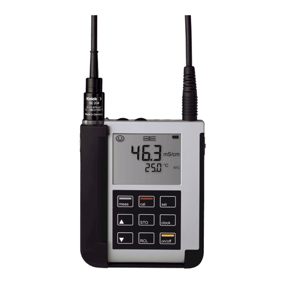
Page 8: Overview Of The Portavo 904(X) Cond
Overview of the Portavo 904(X) COND The Portavo 904(X) COND is a portable conductivity meter. A plain-text line on the high-contrast LCD screen makes operation virtually self-explanatory. The device vari- ant 904 X COND is available for applications in hazardous locations up to Zone 0. The meter stands out by the following features: •... -
Page 9: Value-Added Features
Overview of the Portavo 904(X) COND Value-Added Features Memosens The Portavo 904 can communicate with Memosens sensors. These digital sensors are automatically identified and the meter switches to the appropriate measurement method. When a Memosens sensor is connected to the meter, it is indicated by the logo shown on the right. -
Page 10: Protective Cover
Overview of the Portavo 904(X) COND Protective Cover The front of the meter is protected by a cover, which can be completely flipped over and secured to the back for oper- ation. A label on the inner side of the cover explains the control functions and device messages. -
Page 11: Display
Overview of the Portavo 904(X) COND Display The meter has a three-line display for representing alphanumeric informa- tion such as measurement and calibra- tion data, temperatures and date/time. Additional information is provided by means of icons (Sensoface, battery icon, etc.). Some typical displays are shown here. -
Page 12: Keypad
Overview of the Portavo 904(X) COND Keypad The keys of the membrane keypad have a noticeable pressure point. They have the following functions: on/off Switches the meter on and displays the device and calibration data (see Start-up) meas Switches the meter on / Activates measuring mode / Stops the data logger Starts calibration... -
Page 13: Start-Up
Start-Up Check the shipment for transport damage and completeness (see Package Contents). Caution! Do not operate the device when one of the following conditions applies: • the device shows visible damage • the device fails to perform the intended function •... -
Page 14: Batteries For Application In Hazardous Locations
Start-Up A battery icon in the display indicates the battery power level: Icon fully filled Batteries at full capacity Icon partially filled Battery capacity is sufficient Icon empty Battery capacity not sufficient; calibration is possible, no logging Icon blinks Max. 10 operating hours remaining, measurement is still possible Caution! It is absolutely necessary to replace the batteries. -
Page 15: Connecting A Sensor
Start-Up Connecting a Sensor The Portavo 904(X) COND provides several connections so that many types of sensors can be used for measurement (see illustration below). Note that only one sensor may be connected to the meter at a time. The meter automatically recognizes a connected Memosens sensor and switches accordingly. -
Page 16: Switching On The Meter
Start-Up Switching On the Meter When you have connected the sensor, you can switch the meter on by pressing the on/off or meas key. When the meter is switched on with the on/off key, first a self test is performed and then the calibration data and settings are displayed before the meter switches to measuring mode. -
Page 17: Configuring
Configuring Conductivity Configuration Prior to measurement, a configuration should be performed to match the connected sensor and the desired measurement performance. Furthermore, you can select the suitable calibration method. The following table gives you an overview. Factory settings are shown in bold print. Measurement “Setup”... -
Page 18: Calibrating
Calibrating CELL CONST Calibration (Calibration by entry of cell constant) The calibration method is selected in the configuration menu. Measurement CELL CONST. Value blinks to select the value for the cell constant. Calibration is performed. Automatic return to measuring mode. COND Calibration (Calibration by entry of cell conductivity) The calibration method is selected in the configuration menu. - Page 19 Calibrating 0.1 / 0.01 MOL KCL Calibration (Automatic calibration with KCl solution) The calibration method is selected in the configuration menu. Caution! Make sure that the values of the calibration solutions used corre- spond exactly to those specified in this manual. If not, the resulting cell constant will be incorrect.
- Page 20 Calibrating FREE CAL Calibration (Free selection of calibration method) FREE CAL calibration is selected in the configuration menu. Measurement to select the desired calibration CELL CONST. blinks method (CELL CONST., COND, 0.01 MOL KCL or 0.1 MOL KCL). Perform the selected calibration (see CELL CONST., COND or 0.01/0.1 MOL KCL calibration).
-
Page 21: Measuring
Measuring Keys for Once you have completed all preparations, you can start measurement with the actual measurement. 1) Connect the desired sensor to the meter. Some sensors require a special preparation. Please proceed according to the operating instructions for the sensor. 2) Switch the meter on using the on/off or meas key. -
Page 22: Data Logger
Data Logger The Data Logger The meter provides a data logger. Prior to use, it must be configured and then activated. You can choose from the following logger types: • DIFF (signal-controlled logging of measured variable and temperature) • INT (time-controlled logging at a fixed interval) •... -
Page 23: Operating Modes Of The Data Logger (Logger Type)
Data Logger Operating Modes of the Data Logger (Logger Type) Manual logging when logger is activated (SHOT) In this mode, a measured value is recorded when the STO key is pressed. Measurement Logger activated The measured value is saved to the address of the last recorded value + 1 Manual logging when logger is deactivated Measurement Logger deactivated... - Page 24 Data Logger Difference (DIFF) When the delta range (process variable and/or temperature) related to the last entry is exceeded, a new entry is created and the delta range is displaced upwards or downwards by the delta value. The first entry is automatically created when the data logger is started.
-
Page 25: Data Logger Menu
Data Logger Data Logger Menu Select using arrow keys, confirm by pressing set. Logger display CONT Select start address and start the data logger START Deletes all entries and starts the data logger at start address 0001 Deletes all entries Select logger type and configure: DIFF, INT, DIFF+INT, SHOT (see table below) Overview of data logger menu (default in bold print) -
Page 26: Configuring The Data Logger
Data Logger Configuring the Data Logger Prerequisite: The data logger is stopped (press meas). Measurement Measured value is maintained Logger: CONT blinks Logger: START blinks Logger: DEL blinks Logger: SET blinks Logger: Current logger type Select desired logger type using st: blinks DIFF, INT, DIFF+INT or SHOT. -
Page 27: Starting The Data Logger Using Cont
Data Logger Starting the Data Logger using CONT Prerequisite: Data logger is configured. Every time the meter has been switched off, the data logger must be restarted (exception: SHOT). Measurement Measured value is maintained Logger: CONT blinks Address of the last recorded value If desired: Select start address using st. -
Page 28: Displaying The Logger Data
Data Logger Displaying the Logger Data Pressing the RCL key displays all stored values. The Paraly SW 112 software allows convenient management of the data logger. Measurement The “RCL” icon and the last Use st to select the desired address. recorded value is displayed. Empty memory locations will also be displayed. -
Page 29: Stopping The Data Logger
Data Logger Stopping the Data Logger You can stop the data logger at any time by pressing the meas key. Measurement, logger activated Data logger is stopped. “LOGGER” and “active logger type” icons are no longer displayed. It is still possible to hold a measured value by pressing STO and send it to any desired address. -
Page 30: Clock
Clock Press the clock key to access the clock mode. Date and time will be displayed in the format as set in the configuration menu. To set the clock, proceed as follows: Display of time+date Hour display blinks Set value. SET HOUR Minute display blinks Set value. -
Page 31: Paraly Sw 112 Software
Paraly SW 112 Software The Paraly SW 112 software supplements the Portavo series. It allows convenient management of the data that have been acquired by the meters as well as simple and clear configuration of the meters. Paraly SW 112 starts automatically when the Portavo USB port is connected to the computer. -
Page 32: Error Codes And Device Messages
Error Codes and Device Messages Error messages are indicated as “ERROR …” on the display. Information on the sensor condition is indicated by the “Sensoface” icon (friendly, neutral, sad) possibly accom- panied by an info message (“INFO …”). Example of an error message: Example of a “Sensoface”... -
Page 33: Sensoface" Messages
Error Codes and Device Messages “Sensoface” Messages The “Sensoface” icon provides information on the sensor condition: Sensoface Meaning Sensor is okay Calibrate the sensor soon Calibrate or replace the sensor The “neutral” and “sad” Sensoface icons are accompanied by an “INFO …” message to give a hint to the cause of deterioration. -
Page 34: Error Messages
Error Codes and Device Messages Error Messages The following error messages can be shown in the display. Message Cause Remedy Battery empty Replace batteries blinks ERROR 1 Value out of range Check whether the measurement conditions correspond to the Temperature value out of ERROR 3 adjusted measuring range. -
Page 35: Product Line
Product Line Sensors Analog conductivity sensors Order No. 2-electrode sensor, 120 mm, NTC 30k SE 202 4-electrode sensor, 120 mm, NTC 30k SE 204 4-electrode sensor with glass body ZU 6985 (connection via ZU 0290 adapter) Digital conductivity sensors (Memosens) 2-electrode sensor with graphite electrode and SE 215 MS polysulfone body, 120 mm, NTC 30k... -
Page 36: Conductivity Standards
Adapter for connecting a conductivity sensor with ZU 0289 2 banana plugs to the Portavo 904 COND Adapter for connecting the ZU 6985 4-electrode sensor to the ZU 0290 Portavo 904 COND Please visit our website for more information on our product range: www.knick.de. -
Page 37: Specifications
Specifications Conductivity input, Multi-contact for 2-/4-electrode sensors with integrated temp detector analog Measuring ranges SE 202 sensor: 0.01 … 200 μS/cm SE 204 sensor: 0.05 to 500 mS/cm 2-electrode sensors: 0.1 μS * c … 200 mS * c 4-electrode sensors: 0.1 μS * c …... - Page 38 Specifications Conductivity input, M8 socket, 4 pins, for Memosens lab cable Memosens Measuring range SE 215 MS sensor: 10 µS/cm … 20 mS/cm Measuring cycle Approx. 1 s Temperature compensation Linear 0 … 20 %/K, reference temperature adjustable nLF: 0 … 120 °C NaCl HCl (ultrapure water with traces) NH3 (ultrapure water with traces)
- Page 39 Specifications Diagnostics functions Sensor data Manufacturer, sensor type, serial number, operating time (Memosens only) Calibration data Calibration date; cell constant Device self-test Automatic memory test (FLASH, EEPROM, RAM) Device data Device type, software version, hardware version Data retention Parameters, calibration data > 10 years EN 61326-1 (General Requirements) Emitted interference Class B (residential area)
-
Page 40: Index
Index 0.01 or 0.1 mol KCl calibration 19 0000 DELETED (“data deleted” display) 29 AA batteries 13 Accessories 36 Activating the logger 27 Analog sensors, product line 35 Arrow keys 12 ATEX 7 Automatic calibration 19 Batteries 14 Batteries for application in hazardous locations 14 Battery capacity 14 Battery compartment 13 Battery icon 14... - Page 41 Index Configuration, conductivity 17 Configuring the data logger 26 Connecting a sensor 15 Connecting cable for Memosens 15 Connections 15 Connection, USB (battery) 13 Continuous recording of measured values 23 CONT, starting the data logger 27 Cyclic recording of measured values 23 Data logger 22 Data logger, activating 27 Data logger, clearing 29...
- Page 42 Index EC Declarations of Conformity 7 Energizer E91 battery 14 ERROR (error codes) 34 Error messages 32 Error messages, overview 34 Features 8 Field case (accessory) 36 FREE CAL (calibration) 20 Hazardous location, batteries 14 Holding the measured value 23 Hook 10 Hours, display 30 Icons 16...
- Page 43 Index Manual calibration 18 Manual logging 23 meas key 12 meas, stopping the data logger 29 Measured-value recording 23 Measuring 21 Memory for measured values 22 Memosens 9 Memosens connecting cable 15 Memosens lab cable (accessory) 36 Memosens sensors 15 Menu of data logger 25 Menu structure of configuration 17 Menu structure of data logger 25...
- Page 44 Index Quickstart guides 7 Rating plate 10 RCL, displaying the logger data 28 RCL key 12 Real-time clock 8 Rechargeable battery, Li-ion 13 Recorded data, display 28 Reference numbers (accessories) 36 Registered trademarks 3 Replacement quiver (accessory) 36 Return of products under warranty 3 Safety instructions 7 Saving the currently measured value 23 Seconds, display 30...
- Page 45 Index Structure of data logger 25 Suspending the meter 10 Switching on the meter 16 Switching the measured value display 21 Symbols in display 16 T3, temperature class 14 T4, temperature class 14 Table of error messages 34 Table view of configuration 17 Technical data 37 Temperature class 14 Temperature detectors (accessory) 35...
- Page 48 Knick Elektronische Messgeräte GmbH & Co. KG Beuckestr. 22 D-14163 Berlin Phone: +49 (0)30 - 801 91 - 0 Fax: +49 (0)30 - 801 91 - 200 Internet: http://www.knick.de knick@knick.de 085133 TA-209.4CD-KNE01 20130102 Software version: 1.x...
Need help?
Do you have a question about the Portavo 904 COND and is the answer not in the manual?
Questions and answers