Knick Protos II 4400 Series User Manual
Process analysis system, communication module pid controller module with 2 current outputs and 4 relay outputs
Hide thumbs
Also See for Protos II 4400 Series:
- User manual (112 pages) ,
- Installation manual (2 pages) ,
- Installation manual (2 pages)
Table of Contents
Advertisement
Quick Links
Betriebsanleitung
User Manual
Aktuelle Produktinformation: www.knick.de
Latest Product Information: www.knick.de
Analysenmesssystem
Protos II 4400(X) / Protos 3400(X)
Protos 3400(X)
Process Analysis System
Protos PID 3400(X)-121 Communication Module
Messmodul Protos CONDI 3400 (X)-051
Deutsch
PID Controller Module with 2 Current Outputs and
zur Leitfähigkeitsmessung mit induktiven Sensoren
4 Relay Outputs
The Art of Measuring.
Advertisement
Table of Contents

Related Manuals for Knick Protos II 4400 Series


Summary of Contents for Knick Protos II 4400 Series
- Page 1 Process Analysis System Betriebsanleitung Protos PID 3400(X)-121 Communication Module Messmodul Protos CONDI 3400 (X)-051 User Manual Deutsch PID Controller Module with 2 Current Outputs and zur Leitfähigkeitsmessung mit induktiven Sensoren 4 Relay Outputs Aktuelle Produktinformation: www.knick.de Latest Product Information: www.knick.de...
-
Page 2: Returns
Trademarks The following trademarks are used in this document without further marking: Calimatic®, Protos®, Sensocheck®, Sensoface®, Unical®, VariPower®, Ceramat®, SensoGate® are registered trademarks of Knick Elektronische Messgeräte GmbH & Co. KG, Germany Memosens® is a registered trademark of Endress+Hauser Conducta GmbH & Co. KG, Germany... -
Page 3: Table Of Contents
Table of Contents Returns ............................2 Disposal ............................2 Trademarks ........................... 2 Intended Use ....................5 Safety Instructions ..................6 Operation in Explosive Atmospheres: PID 3400X-121 Module ......... 6 Firmware Version .................... 7 Terminal Plate ....................9 Installing the Module ..................10 Wiring Examples .................... - Page 4 Table of Contents...
-
Page 5: Intended Use
Intended Use The module is a general-purpose PID controller module. Analog control valves are actuated via 2 passive current outputs. Digital straightway valves are actu- ated via 2 relay contacts. In addition, two relay contacts are provided for limit monitoring or pre-control. The PID 3400X-121 module is intended for operation in locations subject to explosion hazards which require equipment of Group II, device category 2(1), gas/dust. -
Page 6: Safety Instructions
• In hazardous locations the device shall only be cleaned with a damp cloth to prevent electrostatic charging. Maintenance The Protos modules cannot be repaired by the user. For inquiries regarding module repair, please contact Knick Elektronische Messgeräte GmbH & Co. KG at www.knick.de. -
Page 7: Firmware Version
Firmware Version Module Firmware PID 3400(X)-121: firmware version 1.x Module Compatibility PID 3400-121 PID 3400X-121 Protos 3400 from FRONT firmware version 1.0 Protos 3400X from FRONT firmware version 4.0 Protos II 4400 from FRONT firmware version 1.0.0 Protos II 4400X from FRONT firmware version 1.0.0 Query actual device/module software When the analyzer is in measuring mode: Press menu key, open Diagnostics menu: Device description... -
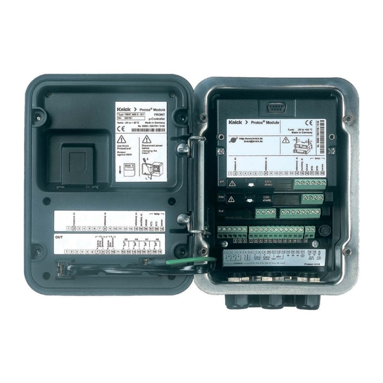
Page 9: Terminal Plate
Terminal Plate Terminal Plate PID 3400-121 Module Attaching the Terminal Plates The terminal plates of the lower modules can be sticked to the inner side of the door. This facilitates maintenance and service. -
Page 10: Installing The Module
Installing the Module CAUTION! Electrostatic discharge (ESD). The modules’ signal inputs are sensitive to electrostatic discharge. Take measures to protect against ESD before inserting the module and wiring the inputs. Note: Strip the insulation from the wires using a suitable tool to prevent dam- age. -
Page 11: Wiring Examples
Wiring Examples Analog and Digital Controller Outputs Wiring Example 1 Analog controller outputs IV 1, IV 2 (passive, supply unit required) Controller output Supply unit IV 1 IV 2 0(4) ... 20 mA Module... - Page 12 Wiring Examples Relay Contacts Wiring Example 2 Digital controller outputs KV 1, KV 2 (electronic relay contacts) Relay contact KV 1 KV 2 Max. 30 V DC 100 mA Module Power supply, e.g. 24 V DC Wiring Example 3 Electronic relay contacts K 9, K 10 Limit contact K 10 Max.
-
Page 13: Pid Controller
PID Controller Short Introduction PID control requires a closed loop. The control loop is made up of individual components which must be in permanent operation. The process variable to be controlled (controlled variable) is continuously measured and compared with the desired value (setpoint). The aim is to keep the controlled variable at the setpoint. - Page 14 PID Controller Short Introduction P Controller (Parameter: Controller Gain) The proportional-action component of a P controller transforms the control deviation (error variable) to a proportional controller output (manipulated variable). The range of the manipulated variable is limited. Therefore, also the usable range of the controller input signal (control range) is limited.
- Page 15 PID Controller Short Introduction I Controller (Parameter: Reset Time) The integral-action component takes account of the rate of change of the manipulated variable, i.e. it forms the time integral of the error variable. Each value of the controlled variable is assigned to a particular rate of change of the manipulated variable.
- Page 16 PID Controller Short Introduction D Control (Parameter: Derivative) A derivative control alone is completely unsuitable since it only reacts to changes of the error variable, that is, constant errors remain unnoticed. PD Controller This controller adds the proportional change of the input signal and the rate of change of the controlled variable to the resulting manipulated variable.
- Page 17 PID Controller Short Introduction The maximum overshoot of the PID controller is even smaller than that of the PD controller. Due to its I-action component there is no remaining offset. However, the components (P, I, D) of a PID controller implement a universally applicable, classical controller thanks to the fast reaction of the P component, the regulating capacity of the I component, and the attenuating effect of the D component.
-
Page 18: Analog Controller Iv1/Iv2
Linear PID Controller Analog Controller IV1/IV2 Analog Controller IV1/IV2 The following controller characteristics can be defined: • Values are adjusted toward the setpoint. • In the neutral zone (symmetrical to setpoint) no control takes place. • Controller parameters: Controller gain, reset, and derivative. •... -
Page 19: Pi Controller With Vertices (Analog Controller Iv1/Iv2)
Nonlinear PI Controller Analog Controller IV1/IV2 PI Controller with Vertices (Analog Controller IV1/IV2) For control of pH neutralization processes, a nonlinear controller (controller with vertices) often provides better results since the control curve can be better adapted to a titration curve. The PID 3400(X)-121 controller module provides an additional nonlinear PI con- troller. - Page 20 Characteristic of Nonlinear PI Controller Analog Controller IV1/IV2 Controller output Y [%] Output range Output range below X W above X W Vertex < Setpoint X W Limit contact 1 [e.g. pH = 7] ("alkali valve") Limit contact 2 ("acid valve") Vertex >...
- Page 21 PID Controller Analog Controller IV1/IV2 Proportional Action (Gradient K [%]) 100 % = 200 % = 500 % = 100 % 50 % = 50 % CR*0.2 CR*0.4 CR*0.6 CR*0.8 Deviation (CR: control range) Variable Control range CR 500 mV 50 % %Air 50 %...
-
Page 22: Digital Controller Kv1/Kv2
PID Controller Digital Controller KV1/KV2 Pulse Length Controller The pulse length controller is used to operate a valve as an actuator. It switches the contact on for a time that depends on the controller output (Y). The period is constant. A minimum ON time of 0.5 sec is maintained even if the controller output takes corresponding values. -
Page 23: Pid Controller And Limit Contacts
PID Controller and Limit Contacts User-defined variables Measuring module Controller Limit value (measured variable) PH (depending on pH, ORP, °C pH, ORP, °C, rH model) COND S/cm, °C S/cm, % by wt, °C, g/kg, Ω*cm CONDI S/cm, °C S/cm, % by wt, °C, g/kg, Ω*cm %Air, %O %Air, %O , mbar, nA, °C, mg/l... -
Page 24: Parameter Setting
Parameter Setting CAUTION! Incorrect parameter setting, calibration or adjustment may result in incorrect measurements being recorded. Protos must therefore be commissioned by a system specialist, all its parameters must be set, and it must be fully adjusted. NOTICE! The "function check” (HOLD) mode is active during parameter setting. The behavior of the current outputs depends on the parameter setting, i.e., they may be frozen at the last measurement or set to a fixed value. -
Page 25: Parameter Setting: Operating Levels
Parameter Setting: Operating Levels Viewing level, Operator level, Administrator level Note: Function check (HOLD) mode active (Setting: BASE module) Viewing level, Operator level, Menu Display Administrator level 11.03 pH Open parameter setting 25.6 °C From the measuring mode: Menu selection Press menu key to select menu. -
Page 26: Parameter Setting: Locking A Function
Parameter Setting: Locking a Function Administrator level: Enabling/locking functions for Operator level Note: Function check (HOLD) mode active (Setting: BASE module) Administrator level: Menu Display Enable / lock functions Example: Blocking access to the calibration adjustments from the Operator level 11.03 pH Open parameter setting 25.0°C... -
Page 27: Configuring The Module
Configuring the Module Menu Display Parameter setting Open parameter setting 11.03 pH 25.0°C From the measuring mode: Menu selection Press menu key to select menu. Select parameter setting using arrow keys, press enter to confirm. Select: [enter] Return to meas Lingua 11.03 pH Select “Module PID”. - Page 28 Parameter Setting Default Settings and Selection Range Note: Function check (HOLD) mode active Parameter Default Selection / Range Controller: PID, linear Analog controller IV1/IV2 • Controller type Off, 3-way mixing valve, straightway valve • Controlled variable (Module) Depending on modules installed, e.g.: S/cm, °C, %Air, %O 2 , mg/l, pH, ORP •...
- Page 29 Parameter Setting Default Settings and Selection Range Note: Function check (HOLD) mode active Parameter Default Selection / Range Digital controller KV1/KV2 • Controller type Off, 3-way mixing valve, straightway valve • Controlled variable (Module) Depending on modules installed, e.g.: S/cm, °C, %Air, %O 2 , mg/l, pH, ORP, ...
-
Page 30: Maintenance
Maintenance Analog Controller, Digital Controller Note: Function check (HOLD) mode active Menu Display Maintenance Call up Maintenance 7.10 pH 22.3 °C From the measuring mode: Menu selection Press menu key to select menu. Select maintenance using arrow keys, press enter to confirm. Select: [enter] Then select Module PID. -
Page 31: Diagnostic Functions
Diagnostic Functions Select menu: Diagnostics Menu Display Function 0.020 µS/cm Opening the diagnostics menu 22.3 °C From the measuring mode: Menu selection Press menu key to select menu. Select diagnostics using arrow keys, confirm by pressing enter. Select: [enter] Then select "Module PID". Return to meas Lingua 0.020 µS/cm... -
Page 32: Opening The Diagnostics Menu
Diagnostic Functions General status information of the measuring system Select menu: Diagnostics - Message list Menu Display Diagnostic functions Opening the diagnostics menu 7.00 pH 25.6°C From the measuring mode: Menu selection Press menu key to select menu. Select diagnostics using arrow keys, confirm by pressing enter. - Page 33 Messages Messages for PID 3400(X)-121 Module with Protos 3400(X) PID messages Message type R008 Meas. processing (factory settings) FAIL R009 Module failure (Firmware Flash check sum) FAIL R014 Feed time A controller Alarm HI_HI FAIL R019 Feed time D controller Alarm HI_HI FAIL R073 Current IV1 Load error...
-
Page 35: Specifications
Specifications Specifications Protos PID 3400(X)-121 Analog controller outputs 0/4... 20 mA, passive IV1, IV2 Supply voltage 3 ... 30 V, I max = 100 mA Load monitoring Error message if load is exceeded Measurement error < 0,25 % current value + 0.05 mA Usage Actuation of analog control valves •... - Page 36 Man. controller output Manual specification for testing or starting up a process, bumpless switchover to automatic when I-action component ≠ 0000 s Pulse period 0001 s (pulse length controller) Switching output K9/K10 Electronic relay outputs, polarized, floating, connected to each other and to KV1, KV2 Voltage drop <...
- Page 37 Specifications General data Explosion protection See certificates or www.knick.de (Ex version of module only) RoHS conformity According to EU directive 2011/65/EU EN 61326-1, EN 61326-2-3 NAMUR NE 21 Emitted interference Industrial applications* (EN 55011 Group 1 Class A) Interference immunity...
-
Page 38: Overview
Overview Overview of Parameter Setting Parameter Setting Menu Parameter Setting 7.00 pH 25.6 °C From measuring mode: Press menu key to select menu. Menu selection Select parameter setting using arrow keys, press enter to confirm. Administrator level Select: [enter] Access to all functions, also passcode setting. Releasing or Return to meas Lingua blocking functions for access from the Operator level. - Page 39 Overview Overview of Parameter Setting Parameter Setting Menu FRONT Module: Display Settings Language Select the menu language Units Select the measurement units Formats Select the display format Measurement display Representation of measured values on the display Display Brightness/contrast, auto-off BASE Module: Signal Outputs and Inputs, Contacts Output current I1, I2 Separately adjustable current outputs Contact K4...
- Page 40 Parameter Setting of PID 3400(X)-121 Module Parameter Default Selection / Range Controller: PID, linear Analog controller IV1/IV2 • Controller type Off, 3-way mixing valve, straightway valve • Controlled variable (Module) Depending on modules installed, e.g.: S/cm, °C, %Air, %O 2 , mg/l, pH, ORP •...
- Page 41 Parameter Setting of PID 3400(X)-121 Module Parameter Selection / Range Default Digital controller KV1/KV2 • Controller type Off, 3-way mixing valve, straightway valve • Controlled variable (Module) Depending on modules installed, e.g.: S/cm, °C, %Air, %O 2 , mg/l, pH, ORP, ... •...
- Page 42 Maintenance Menu BASE Module Output current definable 0 ... 22 mA Current source PID 3400(X)-121 Module Current source Output current definable 0 ... 22 mA Analog controller IV1/IV2 Controller output can be entered manually (function test) Digital controller KV1/KV2 Controller output can be entered manually (function test) Diagnostics Menu Message list List of all warning and failure messages...
-
Page 43: Index
Index Administrator level 25 Analog controller IV1/IV2 18, 19 Analog controller, maintenance menu 30 Analog controller, wiring 11 Application in hazardous locations 6 Characteristic of nonlinear PI controller 20 Configuring the module 27 Controller characteristic 17 Controller characteristic of analog controller 18, 20 Controller characteristic of PI controller with vertex points 20 Controller, wiring 11 Control range 21... - Page 44 Index Firmware version 7 Hardware and firmware version 7 I controller (Parameter: reset time) 15 Inserting the module 10 Installation, inserting the module 10 Intended use 5 Linear PID controller 18 Lock icon 26 Locking a function 26 Maintenance 30 Manual controller output 30 Message list 32 Messages 32...
- Page 45 Index Operating levels 25 Operator level 25 Output status 31 Overview of parameter setting 38 Parameter setting 24 Parameter setting, overview 38 P controller (Parameter: controller gain) 14 PI controller 15 PI controller with vertices 19 PID controller 13 Process variable, user-defined 23 Proportional action 21 Pulse frequency controller 22 Pulse length controller 22...
- Page 46 Index Table of contents 3 Technical data 35 Terminal plate 9 Trademarks 2 User-defined variables 23 Viewing level 25 Wiring examples 11...
- Page 48 Knick Elektronische Messgeräte GmbH & Co. KG Headquarters Beuckestraße 22 • 14163 Berlin Germany Phone: +49 30 80191-0 Fax: +49 30 80191-200 info@knick.de www.knick.de Local Contacts www.knick-international.com Copyright 2019 • Subject to change Version: 8 This document was published on September 30, 2019.
Need help?
Do you have a question about the Protos II 4400 Series and is the answer not in the manual?
Questions and answers