Table of Contents
Advertisement
Quick Links
Betriebsanleitung
Betriebsanleitung
User Manual
Aktuelle Produktinformation: www.knick.de
Aktuelle Produktinformation: www.knick.de
Latest Product Information: www.knick.de
Analysenmesssystem
Analysenmesssystem
Protos 3400(X)
Protos 3400(X)
Protos 3400(X)
Process Analysis System
Messmodul Protos CONDI 3400 (X)-051
Messmodul Protos CONDI 3400 (X)-051
Measuring Module Protos CONDI 3400(X)-051
Deutsch
Deutsch
English
zur Leitfähigkeitsmessung mit induktiven Sensoren
zur Leitfähigkeitsmessung mit induktiven Sensoren
For Conductivity Measurement with Electrodeless
Sensors
The Art of Measuring.
The Art of Measuring.
Advertisement
Chapters
Table of Contents

Related Manuals for Knick Protos CONDI 3400(X)-051


Summary of Contents for Knick Protos CONDI 3400(X)-051
- Page 1 Process Analysis System Betriebsanleitung Betriebsanleitung Messmodul Protos CONDI 3400 (X)-051 Messmodul Protos CONDI 3400 (X)-051 User Manual Measuring Module Protos CONDI 3400(X)-051 Deutsch Deutsch English zur Leitfähigkeitsmessung mit induktiven Sensoren zur Leitfähigkeitsmessung mit induktiven Sensoren For Conductivity Measurement with Electrodeless Sensors Aktuelle Produktinformation: www.knick.de...
-
Page 2: Return Of Products Under Warranty
The following trademarks are used in this manual without further marking: CalCheck®, Calimatic®, Protos®, Sensocheck®, Sensoface®, ServiceScope®, Unical®, VariPower®, Ceramat®, SensoGate® are registered trademarks of Knick Elektronische Messgeräte GmbH & Co. KG, Germany Memosens® is a registered trademark of Endress+Hauser Conducta GmbH & Co. KG, Germany Knick Elektronische Messgeräte GmbH &... -
Page 3: Table Of Contents
Table of Contents Protos CONDI 3400(X)-051 Module Return of Products under Warranty ..................2 Disposal ............................2 Trademarks ........................... 2 Intended Use ..........................6 Conformity with FDA 21 CFR Part 11 .................. 6 Safety Information ........................7 Software Version ........................8 Modular Concept ........................ - Page 4 Table of Contents Protos CONDI 3400(X)-051 Module Parameter Setting: Operating Levels ............39 Administrator level ......................39 Operator level ........................39 Viewing level ........................39 Parameter Setting: Locking a Function ................40 Activating Parameter Setting ....................41 Documenting Parameter Setting ..................42 ProgaLog 3000 Software (Option) for Configuration and Documentation ..44 Configuration using "ProgaLog 3000"...
- Page 5 Table of Contents Protos CONDI 3400(X)-051 Module Maintenance ....................73 Diagnostics Functions ................... 74 Opening the Diagnostics Menu ..................74 Point of Meas Description .....................74 Logbook ............................74 Device Description ........................75 FRONT Module ..........................75 BASE Module ..........................75 Module Diagnostics.........................76 Sensor Monitor ..........................76 Cal Record ...........................76...
-
Page 6: Intended Use
Intended Use The module is an input module for conductivity measurement with commer- cially available electrodeless (toroidal) sensors. The CONDI 3400X-051 module is intended for operation in locations subject to explosion hazards which require equipment of Group II, device category 2(1), gas/dust. -
Page 7: Safety Information
• When installing the device in a hazardous location, observe the specifica- tions of the EC-Type-Examination Certificate and, if applicable, of the Control Drawing (download: www.knick.de). • Before commissioning you must prove that the device may be connected with other equipment, such as a supply unit including cables and wires. -
Page 8: Software Version
Software Version CONDI 3400(X)-051 Module Device Software Protos 3400(X) The CONDI 3400-051 module is supported by software version 3.0 or higher. The CONDI 3400X-051 module is supported by software version 4.0 or higher. Module Software CONDI 3400(X)-051 Software version 2.x Query actual device/module software When the analyzer is in measuring mode: Press menu key, open Diagnostics menu: Device description... -
Page 9: Modular Concept
• FIU (Memosens, Unical) (software occupies 2 slots) • Unical probe controller Documentation The basic unit is accompanied by a CD-ROM containing the complete documentation. Latest product information as well as user manuals for earlier software releases are available at www.knick.de. -
Page 10: Short Description
Short Description Short Description: FRONT Module 4 captive screws Transflective LC graphic display for opening the analyzer (240 x 160 pixels) (NOTICE! Make sure that the gasket between FRONT and white backlighting, high resolution and BASE is properly seated and clean!) high contrast. -
Page 11: Short Description: Menu Structure
Short Description: Menu Structure Basic functions: Calibration, Maintenance, Parameter setting, Diagnostics Menu groups Maintenance Parameter setting Diagnostics Calibration Measure Passcode: 1246 1147 2958 Operator level 1989 Administrator level Selection of BASE SYSTEM Message list Module 1 Point of meas Module 1 further FRONT Module 2... - Page 12 Short Description: FRONT Module View into the open device (FRONT module) Slot for SmartMedia card • Data recording The SmartMedia card expands the measurement recorder capacity to > 50000 records. • Exchange of parameter sets 5 parameter sets can be stored on the SmartMedia card, 2 of them can be loaded simultaneously to the analyzer and be switched by remote control.
-
Page 13: Short Description: Base Module
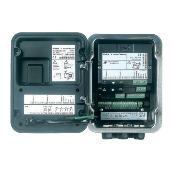
Short Description: BASE Module View into the open device (BASE module, 3 function modules installed) Module equipment Module identification: Plug & Play. Up to 3 modules can be combined as desired. Several input and communication modules are available. Notice Only one module can be connected in addition to a FIU 3400(X)-140/141 module. -
Page 14: Terminal Plate Condi 3400(X)-051 Module
Terminal Plate CONDI 3400(X)-051 Module Terminal Plate CONDI 3400-051 Module Attaching the Terminal Plates The terminal plates of the lower modules can be sticked to the inner side of the door. This facilitates maintenance and service. -
Page 15: Inserting The Module
Inserting the Module Note: Be sure to connect the shielding properly! Make sure that the cable glands are tightly closed to protect against humidity. Switch off power supply Open the device (loosen the 4 screws at the front) Place module in slot (D-SUB connector) Tighten fastening screws of the module Connect sensor cable Close device, tighten screws at the front... -
Page 16: Application Of Se 655 / Se 656 Sensors
Application of SE 655 / SE 656 Sensors Dimension Drawing G 3/4 26,4 Dimensions in mm. -
Page 17: Preparing The Special Cable
Connection of SE 655 / SE 656 Sensors Preparing the Special Cable Preparing the Shield Connection Pre-assembled special cable for SE 655 / SE 656 sensors • Insert the special cable through the cable entry into the terminal compartment. • Remove the already separated part of the cable insulation (1). - Page 18 Wiring Example SE 655/SE 656 Sensor Connecting the pre-assembled cable • The shield wire (*, GN/YE) must be connected to the shielding mesh of the special cable using a crimp ring (see ”Preparing the shield connection”).
- Page 19 Wiring Example SE 660 Sensor Connecting the pre-assembled cable The brown wire is not connected.
-
Page 20: Menu Selection
Menu Selection After switching on, the analyzer performs an internal test routine and automatically detects the number and type of modules installed. Then, the analyzer goes to measuring mode. 0.120 mS/cm 25.1 °C Menu selection 0.120 8.06 24.0°C 25.8°C Select: [enter] Return to meas Lingua... -
Page 21: Passcode Entry
Passcode Entry To enter a passcode Select the position using the left/right keys, then edit the number using the up/down keys. When all numbers have been entered, confirm with enter. To change a passcode • Open the menu selection (menu) •... -
Page 22: Configuring The Measurement Display
Configuring the Measurement Display Select menu: Parameter setting/Module FRONT/Measurement display Pressing meas (1) returns the analyzer to the measuring mode from any function. All process variables coming from the modules can be displayed. The table on the next page describes how to configure the measurement display. Measurement display Typical display for 2 points of measurement: conductivity, pH. - Page 23 Configuring the Menu Display measurement display Configure measurement display 0.120 mS/cm 25.6 °C Press menu key to select menu. Menu selection Select parameter setting using arrow keys, confirm with enter. Select: “Administrator level”: Passcode 1989 Select: [enter] (default setting). Return to meas Lingua 0.120 mS/cm Parameter setting:...
-
Page 25: Calibration / Adjustment
Calibration and adjustment Calibration / Adjustment Note: HOLD mode active for the currently calibrated module Current outputs and relay contacts behave as configured • Calibration: Detecting deviations without readjustment • Adjustment: Detecting deviations with readjustment NOTICE: Without calibration every conductivity meter delivers an imprecise or wrong output value! Mechanical tolerances of the sensor as well as magnetic crosstalk between send and receive coils reduce the measurement accuracy. -
Page 26: Adjustment
Adjustment Adjustment Adjustment means that the cell factor determined by a calibration is taken over. It is entered in the calibration record. (Cal record can be called in the Diagnostics menu for the CONDI 3400(X)-051 module.) The value is only effective for calculating the measured variables when the calibration has been terminated with an adjustment. -
Page 27: Temperature Compensation
Temperature compensation Calibration / Adjustment Temperature Compensation Temperature Compensation During Calibration The conductivity value of the calibration solution is temperature-dependent. For calibration, the calibration solution temperature must therefore be known in order to choose the actual value from the conductivity table. During parameter setting you define whether cal temperature is measured automatically or must be entered manually. -
Page 28: Hold Function During Calibration
Calibration method HOLD Function During Calibration Behavior of the signal and relay outputs during calibration Measuring Calibration K2 contact Module A Selecting the "HOLD" is Module B measuring module active The current output of Module A Module B the selected Calibration Calibration module... - Page 29 Menu Display Select a calibration method Open calibration 1.225 mS/cm 25.6 °C Press menu key to select menu. Menu selection Select calibration using arrow keys, confirm using enter, passcode 1147 (The passcode can be edited by the administrator.) Select: [enter] Return to meas Lingua 1.225 mS/cm...
-
Page 30: Automatic Calibration With Standard Calibration Solution
Automatic calibration Calibration / Adjustment Automatic Calibration with Standard Calibration Solution Automatic with Standard Calibration Solution For automatic calibration, the conductivity sensor is immersed in a standard calibration solution (NaCl or KCl, selected during parameter setting). From the measured conductance and temperature, the Protos automatically calculates the cell factor. - Page 31 Menu Display Automatic calibration 1.225 mS/cm Select calibration menu 25.0 °C Select “Module CONDI” Module CONDI 3400-051 Automatic with standard cal solution Manual entry of cal solution Select calibration method “Automatic Product calibration Data entry - premeasured sensor with standard cal solution”, Zero correction confirm with enter.
-
Page 32: Manual Entry Of Calibration Solution
Manual entry of cal solution Calibration / Adjustment Manual Entry of Calibration Solution Manual Entry of Calibration Solution For calibration with manual entry of the calibration solution’s conductivity, the sensor is immersed in a calibration solution. Protos determines a conductivity/ calibration temperature value pair. - Page 33 Menu Display Manual entry of cal solution 1.225 mS/cm Select calibration menu 25.0 °C Select “Module CONDI” Module CONDI 3400-051 Automatic with standard cal solution Manual entry of cal solution Select calibration method Product calibration Data entry - premeasured sensor “Manual entry of cal solution”, Zero correction confirm with enter.
-
Page 34: Product Calibration
Product calibration Calibration / Adjustment Product Calibration Product Calibration When the sensor cannot be removed, e.g. for sterility reasons (for biotechnical processes), its cell factor can be determined with “sampling”. To do so, the currently measured process value is stored by the Protos. Immediately afterwards, you take a sample from the process. - Page 35 Menu Display Product calibration 1.225 mS/cm Select calibration menu 25.0 °C Select “Module CONDI” Module CONDI 3400-051 Automatic with standard cal solution Manual entry of cal solution Calibration method Product calibration Data entry - premeasured sensor “Product calibration”, Zero correction confirm with enter.
-
Page 36: Data Entry Of Premeasured Sensors
Data entry of premeasured sensors Calibration / Adjustment Data Entry of Premeasured Sensors Data Entry of Premeasured Sensors Entry of cell factor and zero point of a sensor, related to 25°C, 1013 mbars. During calibration the module is in HOLD mode. Current outputs and relay contacts of the module behave as configured (Module BASE). -
Page 37: Zero Correction
Zero correction Calibration / Adjustment Zero Correction Zero Correction Adjustment of zero point / Automatic determination of the zero point in air Every electrodeless (toroidal) conductivity sensor has its individual zero point. When measuring low conductivity values, accuracy can be increased by adjusting the zero point. -
Page 39: Parameter Setting: Operating Levels
Parameter setting Parameter Setting: Operating Levels Viewing level, Operator level, Administrator level Note: HOLD mode (Setting: BASE module) Viewing level, Operator level, Menu Display Administrator level 0.120 mS/cm Open parameter setting 25.6 °C From the measuring mode: Menu selection Press menu key to select menu. Select parameter setting using arrow keys, press enter to confirm. -
Page 40: Parameter Setting: Locking A Function
Parameter Setting: Locking a Function Administrator level: Enabling/locking functions for Operator level Note: HOLD mode (Setting: BASE module) Administrator level: Menu Display Enable / lock functions Example: Blocking access to the calibration adjustments from the Operator level 0.120 mS/cm Open parameter setting 25.0°C Parameter setting (Administrator) Select Administrator level. -
Page 41: Activating Parameter Setting
Activating Parameter Setting Activating parameter setting Menu Display Parameter setting Activating parameter setting 0.120 mS/cm 25.0°C From the measuring mode: Menu selection Press menu key to select menu. Select parameter setting using arrow keys, press enter to confirm. Select: [enter] Passcode as delivered: 1989 Return to meas Lingua... -
Page 42: Documenting Parameter Setting
Documenting Documenting Parameter Setting You must reproducibly document all parameter settings in the device to achieve a high level of system and device security according to GLP. For that purpose, an Excel file is provided (on the CD-ROM shipped with the basic device) to enter the parameter settings. - Page 43 Documenting Parameter Setting From the application window of the Excel file, select the worksheet for the module the parameter settings of which you want to document. Set the parameters of the respective module and enter the selected values in the corresponding cells of the module worksheet. NOTICE! The "HOLD"...
-
Page 44: Progalog 3000 Software (Option) For Configuration And Documentation
ProgaLog 3000 Software (Option) for Configuration and Documentation The ProgaLog 3000 software is available for convenient configuration of the Protos 3400(X) process analysis system. The user interface can be switched to the Protos display languages English, German, French, Spanish, Italian, Swedish or Portuguese. - Page 45 ProgaLog 3000 Software for Configuration and Documentation 4. Edit configuration data using ProgaLog 3000 When the configuration data have been loaded, the software lists the connected modules with all available configuration parameters: Fig.: ProgaLog 3000 configuration data The parameters are listed according to the modular device structure. All configuration parameters (except the "Sensor data details", which are deter- mined by digital sensors) can be edited at the PC.
- Page 46 ProgaLog 3000 Software for Configuration and Documentation Configuring the parameters, e.g. relay contact usage: Input errors are indicated by red highlighting: 5. Save the configuration data to SmartMedia card 6. Load the configuration data to the 7.00 pH 25.6 °C Protos 3400(X) Copy configuration (Adminstrator) Parameter setting / System control /...
-
Page 47: Configuration Using "Progalog 3000
ProgaLog 3000 Software for Configuration and Documentation Configuration using "ProgaLog 3000" In the "Configurator" menu you can preconfigure a complete Protos 3400(X) process analysis system with up to 3 modules at your PC. 1. Select your configuration from the modular system components offered in the left-hand field. -
Page 48: Parameter Setting
Setting the sensor parameters Parameter Setting Default Settings and Selection Range Note: HOLD mode active Parameter Default Selection / Range Input filter • Pulse suppression Off, On (suppression of input interferences) Sensor data SE 655 • Sensor type SE 652 SE 654 SE 655, SE 656 •... -
Page 49: Tc Process Medium
Parameter Setting TC Process Medium Note: HOLD mode active Menu Display TC process medium 1.225 mS/cm TC process medium 20.1 °C You can choose from: Module CONDI 3400-051 (Administrator) • Linear (input of TC coefficient) Input filter Sensor data • EN 27888 Cal preset values TC process medium •... -
Page 50: Parameter Setting: Concentration Curves
Parameter Setting: Concentration Curves Default Settings and Selection Range (Additional function SW 3400-009) Note: HOLD mode active Parameter Default Selection / Range On, Off Concentration H 2 SO 4 (0-30 %), H 2 SO 4 (32-84 %), H 2 SO 4 (with additional function H 2 SO 4 (92-99 %), HNO 3 (0-30 %), HNO 3 (35-96 %),... - Page 51 Nitric acid HNO c [% by wt] Hydrochloric acid HCl c [% by wt]...
- Page 52 Sodium hydroxide solution NaOH c [% by wt] Table salt solution NaCl c [% by wt]...
-
Page 53: Concentration Table
Concentration Table Select menu: Parameter setting/System control/Concentration table Specifying a concentration solution for conductivity measurement Concentration Table To specify the customer-specific solution, 5 concentration values A-E are entered in a matrix together with 5 temperature values 1-5. To do so, first enter the 5 temperature values, then enter the respective conductivity values for each concentration A-E. - Page 54 Calculation Blocks Select menu: Parameter setting/System control/Calculation Blocks Calculation of new variables from measured variables Calculation Blocks Two measuring modules with all their measured values serve as input for the calculation block. In addition, the general device status (NAMUR signals) is taken into account.
- Page 55 Activating Calculation Blocks Select menu: Parameter setting/System control/Calculation Blocks Combining 2 CONDI measuring modules to Calculation Blocks Combination of 2 CONDI Measuring Modules With three measuring modules the following Calculation Block combinations are possible: I + II , I + III , II + III Two Calculation Blocks can be activated.
-
Page 56: Configuring A Calculation Block
Configuring a Calculation Block Select menu: Parameter setting/System control/Calculation Blocks Setting the process variable to be calculated Calculation Block Menu Display Configure 40.00 µS/cm Select Calculation Block 25.6 °C • Open parameter setting Parameter setting (Administrator) • System control System control Module FRONT 3400-011 •... -
Page 57: Logbook
Logbook Factory setting Logbook, Factory Setting Parameter setting/System control/Logbook Note: HOLD mode Menu Display Logbook, Factory setting 0.120 mS/cm Logbook 25.6 °C Select which messages are to be Logbook (Administrator) logged in the logbook. Log failure Log warning The last 50 events are recorded with Erase logbook date and time. -
Page 58: Messages: Default Settings And Selection Range
Messages Parameter Setting Messages: Default Settings and Selection Range Note: HOLD mode active Parameter Default Selection / Range Messages Limits max Off, device limits max., variable limits* • Conductivity Off, device limits max., variable limits* • Resistivity Off, device limits max., variable limits* •... - Page 59 Setting the Message Parameters Messages Note: HOLD mode active Menu Display Messages Messages 0.220 mS/cm 20.1 °C All parameters determined by the Messages (Administrator) measuring module can generate Message Conductivity Messages Resistivity messages. Messages Concentration • Device limits max: Messages Temperature Messages Salinity Messages are generated when the Return...
-
Page 60: Current Outputs, Contacts, Ok Inputs
Current Outputs, Contacts, OK Inputs Select menu: Parameter setting/Module BASE Note: HOLD mode Parameter setting Menu Display BASE module 0.020 mS/cm Configuring the Current Output 19.2°C • Open parameter setting Module BASE (Administrator) • Enter passcode Output current I2 Contact K4 (NAMUR Failure) •... -
Page 61: Current Outputs: Characteristics
Current Outputs: Characteristics Select menu: Parameter setting/Module BASE • Linear characteristic The process variable is represented by a linear output current curve. Output current Process variable Start • Trilinear characteristic Two additional vertices must be entered: Output current 2nd vertex Y 1st vertex Y Process variable Start... - Page 62 • Function characteristic Nonlinear output current characteristic: allows measurements over several decades, e.g. measuring very low values with a high resolution and high values with a low resolution. Required: Entering a value for 50 % output current. Output current Entry for “50 % point”: e.g.: 10 % of measured value Process variable...
-
Page 63: Output Filter
Output Filter Time interval Time averaging filter To smoothen the current output, a low-pass filter with adjustable time interval can be switched on. When there is a jump at the input (100 %), the output level is at 63 % after the time interval has been reached. The time interval can be set from 0 to 120 sec. -
Page 64: Namur Signals: Current Outputs
Current outputs: Behavior during messages NAMUR Signals: Current Outputs Behavior during messages: HOLD, 22mA signal Behavior during messages Depending on the configuration (“Messages”) 83.1 % Air 19.0°C the current outputs switch to: Behavior during messages • Currently measured value HOLD Current meas. -
Page 65: Namur Signals: Relay Contacts
NAMUR Signals: Relay Contacts Failure, maintenance request, HOLD (function check) As delivered, the floating relay outputs of the BASE module are assigned to the NAMUR signals: Failure Contact K4, normally closed (signaling current failure) Maintenance request Contact K3, normally open contact HOLD Contact K2, normally open contact NAMUR signals: Factory setting of contacts... -
Page 66: Relay Contacts: Protective Wiring
Relay Contacts: Protective Wiring Protective wiring of relay contacts Relay contacts are subject to electrical erosion. Especially with inductive and capacitive loads, the service life of the contacts will be reduced. For suppres- sion of sparks and arcing, components such as RC combinations, nonlinear resistors, series resistors and diodes should be used. -
Page 67: Relay Contacts, Usage
Relay contacts Relay Contacts Parameter setting/Module BASE/Relay contacts Menu Display Setting the relay contacts 7.00pH Relay Contacts, Usage 19.2°C • Open parameter setting Contact K1 (Administrator) • Enter passcode Usage NAMUR maintenance Variable NAMUR HOLD • Select “Module BASE” Limit value Limit value •... -
Page 68: Relay Contacts: Sensoface Messages
Relay Contacts: Sensoface Messages Parameter setting/Module BASE/Relay contacts/Usage/Sensoface Menu Display Parameter setting (Sensoface) 7.00 pH Assign Sensoface messages to relay 19.0°C contacts Module BASE (Administrator) Output current I1 When more than one measuring Output current I2 module is used, the Sensoface mes- (NAMUR Failure) Contact K4 Contact K3... -
Page 69: Rinse Contact
Rinse contact Rinse Contact Parameter setting/Module BASE/Relay contacts/Usage/Rinse contact Menu Display Configuring the rinse contact 7.00 pH Relay contacts, usage 19.2°C • Open parameter setting Contact K1 (Administrator) • Enter passcode Usage NAMUR maintenance Variable NAMUR HOLD • Select “Module BASE” Limit value Limit value •... -
Page 70: Icons In The Measurement Display
Limit value Limit Value, Hysteresis, Contact Type Parameter setting/Module BASE/Relay contacts/Usage Menu Usage as limit value 7.00 pH Relay output: Limit value 19.2°C • Open parameter setting Contact K1 (Administrator) • Enter passcode Usage NAMUR maintenance Variable NAMUR HOLD • Select “Module BASE” Limit value Limit value •... -
Page 71: Ok1, Ok2 Inputs: Specify Level
OK1, OK2 Inputs: Specify Level Parameter setting/Module BASE/Inputs OK1, OK2 Note: HOLD mode (Setting: BASE module) Menu Display Setting the OK inputs 7.00 pH OK1 usage 19.2°C • Open parameter setting Inputs OK1, OK2 (Administrator) • Enter passcode For OK2 usage see “Function control matrix”... -
Page 72: Select Parameter Set (A, B) Via Ok2 Input
Switching Parameter Sets via OK2 Parameter setting / System control / Function control matrix Note: HOLD mode (Setting: BASE module) Parameter Sets 2 complete parameter sets (A, B) can be stored in the analyzer. You can switch between the parameter sets using the OK2 input. The currently activated set can be signaled by a relay contact. -
Page 73: Maintenance
Maintenance Sensor monitor Adjusting the temp probe Maintenance Sensor monitor, Temp probe adjustment Note: HOLD mode active Menu Display Maintenance Open Maintenance 1.225 mS/cm 25.6 °C From the measuring mode: Menu selection Press menu key to select menu. Select maintenance using arrow keys, confirm by pressing enter. -
Page 74: Diagnostics Functions
Diagnostics Point of meas description Logbook Diagnostics Functions General status information of the measuring system Select menu: Diagnostics Menu Display Diagnostics functions Opening the Diagnostics Menu 0.002 mS/cm 23.7 °C From the measuring mode: Menu selection Press menu key to select menu. Select diagnostics using arrow keys, confirm by pressing enter. -
Page 75: Device Description
Device description Diagnostics Functions Device description, FRONT module, BASE module Menu Display Diagnostics functions 1.225 mS/cm Device Description 22.7 °C Select module using arrow keys: Device description Module CONDI 3400-051 Provides information about all Inp. electrodeless sensors and °C modules installed: Function, serial Hardware: 1, Software: 2.0 Serial number 0002283 number, hardware and software... -
Page 76: Module Diagnostics
Module diagnostics, Sensor monitor, Cal record Module Diagnostics Module diagnostics, sensor monitor, cal record Module diagnostics / Menu Display Sensor monitor / ServiceScope 1.225 mS/cm Opening the diagnostics menu 22.3 °C From the measuring mode: Menu selection Press menu key to select menu. Select diagnostics using arrow keys, confirm by pressing enter. -
Page 77: Setting Diagnostics Messages As Favorite
Setting diagnostics mes- sages as favorite Setting Diagnostics Messages as Favorite Select menu: Parameter setting/System control/Function control matrix Secondary displays (1) Here, additional values are displayed in the measuring mode according to the factory setting. When the respective softkey (2) is pressed, the process variables measured by the modules plus date or time are displayed. - Page 78 Menu Display Select favorites Favorites menu Diagnostics functions can be called 0.245 directly from the measuring mode using a softkey. The “Favorites” are selected in the Diagnostics menu. Favorites menu 09.03.10 0245 mS/cm Select favorites 25.6 °C Press menu key to select menu. Menu selection Select diagnostics using arrow keys, confirm with enter.
-
Page 79: Message List
Message list Diagnostics Functions General Status Information of the Measuring System Select menu: Diagnostics - Message list Menu Display Diagnostics functions Opening the diagnostics menu 120 mS/cm 25.6°C From the measuring mode: Menu selection Press menu key to select menu. Select diagnostics using arrow keys, confirm by pressing enter. - Page 80 Messages CONDI 3400(X)-051 Module CONDI messages Message type T008 Meas. processing (factory settings) FAIL T009 Module failure (Firmware Flash check sum) FAIL T010 Conductivity range FAIL / WARN T011 Conductivity Alarm LO_LO FAIL T012 Conductivity Alarm LO WARN T013 Conductivity Alarm HI WARN T014 Conductivity Alarm HI_HI...
- Page 81 Messages CONDI messages Message type T044 Salinity Alarm HI_HI FAIL T045 Conductance range FAIL T050 Man. temperature range FAIL T060 SAD SENSOFACE: Primary coil User-defined T061 SAD SENSOFACE: Secondary coil User-defined T062 SAD SENSOFACE: SensoLoop User-defined C120 Wrong ISM sensor FAIL C121 ISM sensor...
-
Page 82: Specifications
Specifications Specifications Protos CONDI 3400(X)-051 CondI input For SE 655 / SE 656 electrodeless sensors (and others) (Ex ia IIC) Measuring range 0000 µS/cm ... 1999 mS/cm, resolution 1 µS/cm (SE 655 / SE 656) Concentration 0.00 ... 100.0 % by wt Salinity 0.0 ... - Page 83 Specifications 0 ... 30 % by wt -17.8 ... +110 °C 32 ... 84 % by wt -17.8 ... +115.6 °C 92 ... 99 % by wt -17.8 ... +115.6 °C NaOH 0 ... 14 % by wt 0 ... +100 °C 18 ...
- Page 84 Specifications General data Explosion protection See www.knick.de (Ex module only) NAMUR NE 21 and EN 61326-1 EN 61326-2-3 Emitted interference Class B (residential area) Immunity to interference Industry Lightning protection EN 61000-4-5, Installation Class 2 Nominal operating conditions Ambient temperature: –20 ...
-
Page 85: Appendix
Appendix Minimum Spans for Current Outputs The CONDI 3400(X)-051 module is a measuring module. It does not provide current outputs. Current outputs are provided by the BASE module (basic device) or by communication modules (e.g. OUT module). The corresponding parameters must be set there. The minimum current span shall prevent that the resolution limit of the measurement technology (±... - Page 86 Overview of Parameter Setting Parameter setting 7.00 pH 25.6 °C Activated from measuring mode: Press menu key to select menu. Menu selection Select parameter setting using arrow keys, confirm with enter. Administrator level Access to all functions, also passcode setting. Releasing or Select: [enter] blocking functions for access from the Operator level.
- Page 87 Parameter Setting Menu Display settings: FRONT module Languages Measurement display Representation of measured values on the display: • Main display - Selecting the number of primary values displayed • Display format (one or two) • Viewing angle - Decimal places Measurement recorder Option: 2-channel, selection of process variable, start and end •...
- Page 88 Parameter Setting Menu CONDI 3400(X)-051 Module Input filter Sensor data Representation of measured values on the display: • Sensor type - Select • Sensor coding - Selection for Measurement / Calibration • Nom. cell factor • Transfer ratio • Temperature detection - Measuring temp - Cal temp •...
- Page 89 Calibration Menu CONDI 3400(X)-051 Module Automatic Calibration solution input Product calibration Data entry Zero correction Maintenance Menu BASE Module Current source Output current definable 0 ... 22 mA CONDI 3400(X)-051 Module Sensor monitor Resistance, conductance, RTD, temperature Temp probe adjustment Compensating for lead length Diagnostics Menu Message list...
-
Page 90: Index
Index Adjustment ..........................26 Administrator level ........................39 Application in hazardous locations ..................7 Automatic calibration with standard calibration solution .........30 Automatic temperature compensation ................27 BASE module ..........................13 Behavior during messages ....................64 Cable glands..........................10 Calculation Blocks ........................54 Calibration ...........................25 Cal record .............................76 Change passcode ........................21 Concentration ..........................50 Concentration curves ......................50... - Page 91 Index Dimension drawing of sensors.....................16 Disposal ............................2 Documenting parameter setting .................42, 43 EMC ..............................84 Explosion protection ........................84 Factory setting ...........................57 Failure, signaling ........................65 Favorites ............................77 FDA 21 CFR Part 11 ........................6 FRONT module ...........................12 Function check ...........................65 Graphic display ..........................10 Hardware and software version .....................
- Page 92 Index Logbook, diagnostics menu ....................74 Logbook, parameter setting ....................57 Maintenance ..........................73 Manual entry of cal solution ....................32 Menu selection ...........................20 Menu structure ...........................11 Message icons ..........................59 Message list ..........................79 Messages ............................59 Messages, response of current outputs ................64 Message when the current range is exceeded ..............64 Minimum spans for current outputs ..................85 Modular concept .........................
- Page 93 Index Parameter setting ........................39 Parameter setting, documenting ..................42 Parameter setting: TC process medium ................48 Passcode entry ...........................21 Passcode lost ..........................21 Point of meas description ......................74 Preparing the special cable ....................17 Product calibration ........................34 ProgaLog 3000 software ......................44 Protective wiring ........................66 Relay contacts, protective wiring ..................66 Relay contacts, usage ......................67 Relay output, limit value ......................70...
- Page 94 Index Slot for SmartMedia card......................12 SmartMedia card ........................12 Sodium hydroxide solution ....................52 Softkeys ............................77 Software version .......................... 8 Specifications ..........................82 Sulfuric acid ..........................50 Switching parameter sets via OK2 ..................72 Table of contents ......................... 3 TC correction ..........................49 Temperature compensation during calibration.............27 Temperature probe adjustment ..................73 Temp probe adjustment ......................73 Terminal compartment ......................13...
- Page 95 Icon Explanation of Icons Important for this Module The analyzer is in measuring mode. The analyzer is in calibration mode. HOLD mode active for the currently calibrated module The analyzer is in maintenance mode. HOLD mode active. The analyzer is in parameter setting mode. HOLD mode active. The analyzer is in diagnostics mode.
-
Page 96: Menu Selection
Menu Selection CONDI 3400(X)-051 Module Calibration and adjustment ...........25 Adjustment .....................26 Temperature compensation ..............27 Calibration method ..................28 Automatic calibration .................30 Manual entry of cal solution ..............32 Product calibration ..................34 Data entry of premeasured sensors ............36 Zero correction ....................37 Parameter setting ..............39 Documenting ....................42 Setting the sensor parameters ..............48 Logbook ......................57...
Need help?
Do you have a question about the Protos CONDI 3400(X)-051 and is the answer not in the manual?
Questions and answers