DAB ESYBOX Manual
- Instruction for installation and maintenance (888 pages) ,
- Important information manual (80 pages) ,
- Assembly and dismantling manual (59 pages)
Advertisement
- 1 KEY
- 2 FIELD OF APPLICATION AND PUMPABLE LIQUIDS
- 3 GENERAL
- 4 MANAGEMENT
- 5 INSTALLATION
- 6 COMMISSIONING
- 7 MAINTENANCE
- 8 TECHNICAL DATA
- 9 DESCRIPTION OF CONTROL PANEL
-
10
CONTROL PANEL
- 10.1 Menu
- 10.2 Meaning of the individual parameters
-
10.3
Protection systems
- 10.3.1 Description of blockages
- 10.3.2 Anti-Cycling
- 10.3.3 Anti-Freeze
- 10.3.4 Anti-lock: Protection against pump long blocking
- 10.3.5 "BP1" "BP2" Blockage due to fault of the pressure sensors
- 10.3.6 "PB" Blockage due to supply voltage outside specifications
- 10.3.7 "SC" Blockage due to short circuit between the motor phases
- 10.3.8 Manual reset of error conditions
- 10.3.9 Self-reset of error conditions
- 10.4 Operation with control unit
- 10.5 Reset and factory settings
-
11
PARTICULAR INSTALLATIONS
- 11.1 Disabling self-priming
- 11.2 Installation with quick connection
-
11.3
Multiple Sets
- 11.3.1 Introduction to multipump systems
- 11.3.2 Making a multipump system
- 11.3.3 Wireless communication
- 11.3.4 Connection and setting of the photo-coupled inputs
- 11.3.5 Parameters concerning multipump
- 11.3.6 First start of the multipump system
- 11.3.7 Multipump adjustment
- 11.3.8 Assigning the starting order
- 11.3.9 Maximum switching time
- 11.3.10 Reaching the maximum inactivity time
- 11.3.11 Reserves and number of devices that participate in pumping
- 11.3.12 Wireless control
- 12 APP, CLOUD AND SOFTWARE UPDATE
- 13 SPECIFIC CONFIGURATIONS
- 14 ACCESSORY TOOL
- 15 EXPANSION VESSEL
- 16 MOTOR SHAFT
- 17 NON-RETURN VALVE
- 18 TROUBLESHOOTING
- 19 WARNINGS AND RESIDUAL RISKS
- 20 Documents / Resources
KEY
Safety Signs
The symbols shown below are used (if relevant) in the owner's manual. These symbols have been inserted to alert user personnel to possible sources of danger.
Failure to heed the symbols could result in personal injury, death, and/or damage to the machine or equipment.
Broadly speaking, there are three types of signals (Table 1).
Table 1 Typology of safety signs
| Symbol | Form | Type | Description |
 | Framed triangular shape | Warning Signs | Indicate requirements relating to present or possible hazards |
 | Circular frame | Prohibitory signs | They set out requirements for actions that must be avoided |
 | Full Circle | Mandatory Signs | Indicate information that is mandatory to read and comply with |
 | Circular frame | Information | indicate useful information, other than the types of danger/prohibition/obligation |
Depending on the information to be transmitted, the signs may contain symbols that, by association of ideas, help to understand the type of danger, prohibition or obligation.
The following symbols have been used in the discussion:
WARNING, GENERAL DANGER.
Failure to respect the instructions that follow may cause harm to persons and property.
 WARNING, ELECTRICAL DANGER.
Failure to respect the instructions that follow may cause a situation of grave risk for personal safety. Take care not to come into contact with electricity.
 Notes and general information. Please read the following instructions carefully before operating and installing the machine.
DAB Pumps makes every reasonable effort to ensure that the contents of this manual (e.g. illustrations, texts and data) are accurate, correct and up-to-date. Nevertheless, they may not be free of errors and may not be complete or up-to-date at any time. The company therefore reserves the right to make technical changes and improvements over time, even without prior notice.
DAB Pumps accepts no liability for the contents of this manual unless subsequently confirmed in writing by the company.
FIELD OF APPLICATION AND PUMPABLE LIQUIDS
The device is designed and built to pump only water, free of explosive substances and solid particles or fibers, with a density of 1000 Kg/m3, kinematic viscosity equal to 1 mm2/s and non-chemically aggressive liquids. Use with other fluids is only permitted with the manufacturer's permission.
GENERAL
Product name
ESYBOX
Classification according to European Reg.
BOOSTER
Description
The product is an integrated system consisting of a multi-stage centrifugal electric pump, an electronic circuit that controls it and an expansion tank.
Specific product references
If the product has integrated electronics, see chapter DESCRIPTION OF CONTROL PANEL.
If the product has an integrated expansion tank, see chapter EXPANSION VESSEL.
For technical data, refer to the technical data plate or the dedicated chapter TECHNICAL DATA.
MANAGEMENT
Storage
All pumps must be stored in a covered, dry place with as constant humidity as possible, free of vibrations and dust. They are supplied in their original packaging in which they must remain until the time of installation. If this is not the case, carefully close the suction and delivery port. The product operates correctly with a difference between ambient and liquid temperatures of no more than 30°C (with the ambient temperature higher than the liquid temperature). Besides this temperature difference, the humidity limit must not exceed 50%, otherwise there is a risk of condensation forming, which can cause irreparable damage to the electronic board.
![]() The product can be equipped with the Esycover accessory, which can be purchased separately and is used when the pump is installed in partially protected environments.
The product can be equipped with the Esycover accessory, which can be purchased separately and is used when the pump is installed in partially protected environments.
Transport
Avoid subjecting the product to needless impacts and collisions.
INSTALLATION
- The pumps may contain small amounts of residual water from testing.
- We recommend washing them briefly with clean water before final installation.
- The electric pump must be installed in a well-ventilated place and with an ambient temperature not higher than that indicated in the technical specifications of each product.
- A solid anchoring of the pump to the base supports the absorption of any vibrations created by the operation of the pump.
- Do not allow the metal pipes to transmit excessive stress to the pump ports, so as not to create deformation or breakage.
- It is always a good idea to place the pump as close as possible to the liquid to be pumped.
- The pump must be installed under conditions appropriate to the specificities of the product.
- The system can suck in water whose level does not exceed a depth of 8 m (height between the water level and the suction port of the pump)
- It is recommended to carry out the installation according to the instructions in the manual in accordance with the laws, directives and regulations in force at the site of use and depending on the application.
- The pump is not self-priming. It is suitable for suction from tanks or connected to the aqueduct in relaunch where it is possible according to local regulations.
The product in question contains an inverter inside which there are direct voltages and currents with high-frequency components.
The residual current circuit breaker protecting the system must be correctly sized according to the characteristics indicated in Table 3. For inverters with three-phase power supply, we recommend a residual current circuit breaker that is also protected against untimely trips.
Carefully follow the recommendations in this chapter to achieve proper electrical, plumbing, and mechanical installation. Before you set out on any installation, make sure that you have turned off power to the power line. Strictly observe the power supply values indicated on the electrical rating plate.
Recommended predispositions
Shut-off valves are to be mounted upstream and downstream of the pump in order to avoid having to empty the system in case of maintenance to the pump. For wall mounting, follow the instructions below:
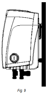
- This product is already designed to be installed suspended on the wall using a DAB accessory kit to be purchased separately.
![]()
Plumbing and piping connection
Make the inlet connection to the system through the suction port indicated in Fig. 1, then remove the cap with the help of an accessory tool or a screwdriver.

Make the connection to the exit of the system through the discharge port indicated in Fig. 1, then remove the cap with the help of an accessory tool or a screwdriver.
All hydraulic connections of the system to the system to which it can be connected are of the 1" female thread type.
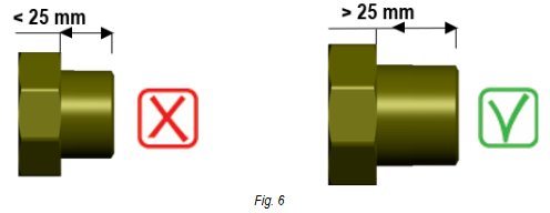
If you intend to connect the product to the plant with fittings that have a diameter larger than the normal 1" pipe (for example the ring nut in the case of fittings in 3 pieces), make sure that the 1" Gas male thread of the coupling protrudes at least 25 mm from the above diameter (Fig. 6).
With reference to its position with respect to the water to be pumped, the installation of the system may be defined "above head" or "below head". In particular the installation is defined "above head" when the pump is placed at a level higher than the water to be pumped (e.g. pump on the surface and water in a well); vice versa it is "below head" when the pump is placed at a level lower than the water to be pumped (e.g. overhead cistern and pump below). See chapter SPECIFIC CONFIGURATIONS.
Electrical connection

Always observe the safety regulations!
A device must be provided in the power supply network that ensures complete disconnection under the conditions of overvoltage category III. When the switch is in the open position, the separation distance of each contact must comply with the instructions in the table below:
Table 2
| Minimum distance between power switch contacts | ||
| Power Supply Range (V) | > 127 and ≤ 240 | > 240 and ≤ 480 |
| Minimum Distance (mm) | > 3 | > 6 |
Make sure that the mains voltage corresponds to the CE marking voltage (technical plate) of the product.
With the unit at full capacity, check that the current absorbed by the motor does not exceed that of the CE marking (technical plate).
To improve immunity to possible radiated noise to other equipment, it is recommended to use a separate electrical conduit for powering the product.
The product in question contains an inverter inside which there are direct voltages and currents with high frequency components (see table below).
Table 3
| Typology of possible ground fault currents | ||||
| Alternating | Pulsating Single-Pole | Direct | With high-frequency components | |
| In the case of single-phase power inverters | ● | ● | ● | |
| In the case of three-phase power inverters | ● | ● | ● | ● |
COMMISSIONING
On the pump, fully open the suction valve and then energize the system.
Priming
Do not start the pump without having completely filled it with liquid, providing that it is completely filled, with clean water, through the appropriate hole, after removing the filler cap.
Dry running causes irreparable damage to the mechanical seal. The filler cap will then need to be screwed back on carefully.
If the product is equipped with software-assisted priming, see chapter Filling system operation.
Starting
For the first start-up, follow these steps:
- To start correctly, make sure that you have followed the instructions in the following paragraphs: INSTALLATION e COMMISSIONING and its subsections;
- Check the actual presence of water;
- Provide electrical power;
- If there are built-in electronics, follow the instructions (see chapter CONTROL PANEL).
Precautions
In the event that hot water is to be pumped, stop the pump only after excluding the heat source and allowing a period of time to elapse so that the temperature of the liquid drops to acceptable values, so as not to create excessive temperature increases inside the pump body.
For a long period of shutdown, close the shut-off device of the suction pipe, and if necessary, if provided, all auxiliary control connections. If long periods of inactivity are to be expected, plan short-term commissioning cycles to avoid deterioration and malfunctions.
FROST HAZARD: when the pump remains inactive for a long time at a temperature below 0°C, it is necessary to proceed with the complete emptying of the pump body through the drain plug, to avoid any cracking of the hydraulic components. This operation is also recommended in case of prolonged inactivity at normal temperature.
Check that the liquid spill does not damage property or people, especially in systems that use hot water. Do not close the drain plug until the pump is used again. Starting after a long period of inactivity requires the repetition of the operations described in paragraph Starting listed above. To avoid unnecessary overloads of the motor, carefully check that the density of the pumped liquid corresponds to that used in the design phase: remember that the power absorbed by the pump increases proportionally to the density of the conveyed liquid.
MAINTENANCE
Before starting any work on the system, disconnect the power supply and wait at least 5 minutes. The system is exempt from routine maintenance. In the event that it is necessary to drain the liquid to carry out maintenance, check that the leakage of the liquid does not damage property or people, especially in systems that use hot water. In addition, the legal regulations for the disposal of any harmful liquids must be observed. After a long period of operation, there may be some difficulties in disassembling the parts in contact with water: for this purpose, use a special solvent found on the market and, where possible, a suitable extractor. It is recommended not to force on the various parts with unsuitable tools.
Periodic checks
The product in normal operation does not require any kind of maintenance. However, it is advisable to periodically check the current absorption, the manometric head with the mouth closed and the maximum flow rate, which allows you to identify faults or wear in advance. The mechanical seal does not normally require any control step. You will only have to check that there is no leak of any kind. If there is a different seal, check the dedicated appendix.
Emptying the system
If you want to drain the water out of the system, proceed as follows:
- Disconnect the power supply;
- Turn on the delivery tap closes to the system so as to remove pressure from the system and empty it as much as possible;
- If there is a check valve immediately downstream from the system (always recommended), close it so as not to let out the water that is in the plant between the system and the first turned on tap;
- Interrupt the suction pipe in the point closest to the system (it is always recommended to have a check valve immediately upstream from the system) so as not to drain the whole suction system;
- Remove the drainage cap and let out the water inside;
- The water that is trapped in the delivery system downstream from the non-return valve integrated in the system can flow out at the time of disconnecting the system, or on removing the cap of the second delivery (if not used).
Though essentially drained, the system is unable to expel all the water that it contains. During handling of the system after emptying it, some small amounts of water may probably leak out from the system.
Modifications and spare parts
Any modification made without prior authorisation relieves the manufacturer of all responsibility.
Only if there is an integrated power cable, in the event of damage to the same, the repair must be carried out by specialized personnel to prevent any risk.
CE marking and minimum instructions for DNA
The image is for representative purposes only

Consult the Product configurator (DNA) available on the DAB PUMPS website.
The platform allows you to search for products by hydraulic performance, model or article number. Technical data sheets, spare parts, user manuals and other technical documentation can be obtained.

https://dna.dabpumps.com/

TECHNICAL DATA
Table 4: Technical Data
| ESYBOX | ||
| Electric power supply | Voltage | 1~ 220-240 VAC |
| Frequency | 50/60 Hz | |
| Maximum current | 10 A | |
| Maximum power | 1550 W | |
| Leakage current to earth | < 2,5 mA | |
| Construction characteristics | Overall dimensions | 565x265x352 mm without feet |
| Empty weight (excluding packaging) | 24,8 kg | |
| Protection class | IP X4 | |
| Motor insulation class | F | |
| Hydraulic performance | Maximum head | 65 m |
| Maximum flow rate | 120 l/min | |
| Priming | < 5min at 8m | |
| Working conditions | Maximum working pressure | 8 bar |
| Liquid temperature max | 40°C * | |
| Environment temperature max | 50°C | |
| Storage environment temperature | -10÷60°C | |
| Functionality and protections | Constant pressure | |
| Wireless communication | ||
| Protection against dry running | ||
| Antifreeze protection | ||
| Anticycling protection | ||
| Motor overload protection | ||
| Protection against abnormal supply voltages | ||
| Protection against excess temperature | ||
* WRAS approved cold water only
DESCRIPTION OF CONTROL PANEL
The electronic control integrated in the system is of the type with inverter and it makes use of flow, pressure and temperature sensors, also integrated in the system. By means of these sensors the system switches on and off automatically according to the utility's needs and it is able to detect conditions of malfunction, to prevent and indicate them. The Inverter control ensures different functions, the most important of which, for pumping systems, are the maintaining of a constant pressure value in delivery and energy saving. The inverter is able to:
- Keep the pressure of a hydraulic circuit constant by varying the rotation speed of the electropump. In operation without an inverter the electropump is unable to modulate and, when there is an increase of the request for flow, the pressure necessarily decreases, or vice versa; this means the pressures are too high at low flow rates or too low when there is an increased request for flow.
- By varying the rotation speed according to the instantaneous request of the utility, the inverter limits the power supplied to the electropump to the minimum necessary to ensure that the request is satisfied. Instead, operation without an inverter contemplates operation of the electropump always and only at maximum power.
The system is configured by the manufacturer to satisfy the majority of installation cases, that is:
- Type of product: booster;
- Operation: constant pressure;
- Set-Point [SP]: desired value of constant pressure. Value configured by the manufacturer SP = 3.0 bar;
- Restart Pressure: Reduction of pressure to restart. Value configured by the manufacturer RP = 0.3 bar;
- Anti-cycling function: Value configured by the manufacturer Disable
For the definition of the parameters SP and RP, the pressure at which the system starts has the value:
P_START = SP – RP = 3.0 - 0.3 = 2.7 Bar
The system does not work if the utility is at a height higher than the equivalent in metres of water column of the Pstart (consider 1 bar = 10 m water column): for the default configuration, if the utility is at a height of at least 27m the system does not start.
Control panel orientation
The control panel is designed to be placed in the most readable direction for the user: the square shape allows it to be rotated 90° by 90° (Fig. 7).

- Unscrew the 4 screws at the corners of the panel with the accessory tool (if supplied) or a normal torx wrench.
- Do not remove the screws completely, it is recommended to unscrew them only from the thread on the body of the product.
- Be careful not to drop the screws into the system.
- Move the panel, taking care not to stretch the signal cable.
- Replace the panel in its seat with the chosen orientation, taking care not to pinch the cable.
- Tighten the 4 screws with the accessory tool (if supplied) or a normal torx wrench.
Filling system operation
The priming of a pump is the phase during which the machine attempts to fill the body and the suction pipe with water. If the operation is successful the machine can work regularly.
Once the pump has been filled and the device has been configured, it is possible to connect the electric power supply after having opened at least one utility on delivery for the first 15 seconds. If a flow of water is detected in delivery, the pump is primed and starts its regular work. This is the typical case of installation below head. The utility opened in delivery from which the pumped water is coming out can be closed. If a regular flow in delivery is not detected after 10 seconds, the system asks for confirmation to enter the priming procedure (typical case of installation above head).

When  is pressed the pump enters the priming procedure: it starts working for a maximum time of 5 minutes during which the safety block for dry operation is not tripped. The priming time depends on various parameters, the most influential of which are the depth of the water level from which it is drawing, the diameter of the suction pipe, the water-tightness of the suction pipe. On condition that a suction pipe is used that is no smaller than 1" and that it is well sealed (with no holes or joins from which it can take in air). As soon as the product detects a regular flow in delivery, it leaves the priming procedure and starts its regular work. The utility opened in delivery from which the pumped water is coming out can be closed. If after 5 minutes of the procedure the product is still not primed, the interface display sends a failure message. Disconnect the power supply, load the product adding new water, wait 20 minutes and repeat the procedure from the moment you put the plug in the socket.
Press  confirm that you do not want to start the priming procedure. The product remains in alarm status.
Operation
Once the electropump is primed, the system starts regular operation according to the configured parameters: it starts automatically when the tap is turned on, supplies water at the set pressure (SP), keeps the pressure constant even when other taps are turned on, stops automatically after time T2 once the switching off conditions are reached (T2 can be set by the user).
CONTROL PANEL
The user interface is composed of a keypad with 320x240 pixel LCD display and with POWER, COMM, ALARM warning leds, respectively white, blue and red.
The display shows the values and the statuses of the device, with indications on the functionality of the various parameters.
The functions of the keys are summed up below:
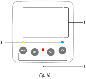
- Display
- Led
![]()
Lit with a fixed light when the machine is powered.
Blinking when the machine is disabled![]()
Lit with a fixed light when communication wireless is used and is working correctly.
Blinking with a slow frequency when communication is not available.
Blinking with a high frequency during association with other wireless devices. Off if communication is not used.![]()
Lit with a fixed light when the machine is blocked by an error - Buttons
![]()
The key allows you to move on to the next items in the same menu. Holding it down allows you to skip to previous menu item. ![]()
The key allows you to leave the current menu ![]()
Press to browse the menu.
Press to increment the selected parameter.
Press and hold to increase the increment speed.![]()
Press to browse the menu.
Press to decrement the selected parameter.
Press and hold to increase the decrement speed.


![]() When the key or the key is pressed the selected value is modified and saved immediately in the permanent memory (EEprom). If the machine is switched off, even accidentally, in this phase it does not cause the loss of the parameter that has just been set.
When the key or the key is pressed the selected value is modified and saved immediately in the permanent memory (EEprom). If the machine is switched off, even accidentally, in this phase it does not cause the loss of the parameter that has just been set.
![]() The
The  key is only for leaving the current menu and is not necessary for saving the changes made. Only in particular cases described in the following paragraphs are some values updated by pressing or
  .
.
Menu
The complete structure of all the menus and of all the items of which they are composed is shown in Table 5.
Access to the menus
The various menus can be accessed from the main menu in two ways:
- Direct access with a combination of keys;
- Access by name with a drop-down menu.
Table 5: Menu structure

 Parameters available in version KIWA
Direct Access
The desired menu can be accessed directly by pressing simultaneously the appropriate combination of keys for the required time (for  example to enter the Setpoint menu) and the various items in the menu are scrolled with the key. Table 6 shows the menus that can be reached with the combinations of keys.
Table 6: Menu accesses

Access by name
The selection of the various menus is accessed by name. From the main menu you access menu selection by pressing either of the or keys. The names of the menus that can be accessed appear on the menu selection page and one of the menus is highlighted by a bar. Shift the highlighting bar using the and to select the menu you want and enter it by pressing .
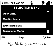
The items available are MAIN, USER, MONITOR, followed by a fourth item, EXTENDED MENU; this item allows the number of menus displayed to be extended. When EXTENDED MENU is selected a pop-up appears asking you to type in an access key. The access key coincides with the combination of keys used for direct access (as in Table 6) and allows the extended display of the menus from the menu corresponding to the access key to all those with a lower priority. The order of the menus is: User, Manual Setpoint, Manual, Installer, Technical Assistance. When an access key is selected, the menus released remain available for 15 minutes or until they are disabled manually by means of the item "Hide forward menus" which appears on the menu selection when using an access key. Nella Fig. 20 shows an operating diagram for selecting the menus. The menus are in the centre of the page, from the right you reach them by means of direct selection with a combination of keys, while from the left you reach them by means of the selection system with dropdown menu.

Structure of the menu pages
When switched on, some presentation pages are displayed showing the name of the product and the logo, after which the main menu appears. The name of each menu, whichever it may be, is always at the top of the display.
The following always appear on the main page:
Status Icons: description in Table 7
Auxiliary Functions Icons: description in Table 8
Pressure: value in bar or psi depending on the set unit of measure.
Flow: value in l/min or gal/min depending on the unit of measure
Power: value in kW of the power absorbed by the device.
In the frame at the bottom of the screen, present on all pages, the following always appear:
Status Label: status labels are described in Table 9;
Blocking Error Description/Alarm Description: caption placed after the FAULT/WARNING label and consisting of the error/alarm acronym and a brief description.
Motor revs: value in rpm.
Pressure: value in bar or psi depending on the set unit of measure.
The list of Errors and Alarms can be found in Table 20 and in Table 21 at chapter Protection systems.
Main Page: Status Icons
Table 7: System Status Icons
| Status | Icon | Description |
| Active |  | Motor running |
| Stopped |  | Motor stopped |
| Disabled |  | Motor manually disabled |
| Error |  | Blocking error: the type of error is shown and described in the bottom left corner of the screen |
| KIWA Sensor Error |  | "Low suction pressure" error signal |
Main Page: Auxiliary Functions Icons
Table 8: Auxiliary Functions Icons
| Icon | Description |
 | Power Shower |
 | Float |
 | Sleep Mode |
Footer: Indications on the status bar
Table 9: Indications on the status bar
| Identifying code | Description |
| GO | Motor running |
| SB | Motor stopped |
| DIS | Motor status manually disabled |
| FAULT | Presence of an error preventing operation of the electropump |
| WARNING | Indicates an Alarm that does not prevent operation of the electric pump |
The other menu pages vary with the associated functions and are described later by type of indication or setting. Once you have entered any menu, the bottom of the page always shows a summary of the main operating parameters (running status or any fault, current speed and pressure). This allows a constant view of the machine's fundamental parameters.
Pages showing parameters can display: numerical values and units of measure of the current item, values of other parameters linked to the setting of the current item, graphic bar, lists.
Blocking parameter setting by Password
The device has a password-enabled protection system. If a password is set, the parameters of the device will be accessible and visible but it will not be possible to change them. The password management system is in the "technical assistance" menu and is managed by means of the parameter PW.
Enabling and disabling the motor
In normal operating conditions, pressing and then releasing both the and keys causes the blocking/release of the motor (selfholding even after switching off). If there is a fault alarm, the operation described above resets the alarm. When the motor is disabled this status is shown by the blinking white LED. This command can be activated from any menu page except RF and PW.
Meaning of the individual parameters
![]() The inverter makes the system work at constant pressure. This regulation is appreciated if the hydraulic plant downstream from the system is suitably sized. Plants made with pipes with too small a section introduce load losses that the equipment cannot compensate; the result is that the pressure is constant on the sensors but not on the utility.
The inverter makes the system work at constant pressure. This regulation is appreciated if the hydraulic plant downstream from the system is suitably sized. Plants made with pipes with too small a section introduce load losses that the equipment cannot compensate; the result is that the pressure is constant on the sensors but not on the utility.
![]() Plants that are excessively deformable can create the onset of oscillations; if this occurs, the problem can be solved by adjusting the control parameters "GP" and "GI" (see paragraph GP: Proportional gain coefficient and GI: Integral gain coefficient)
Plants that are excessively deformable can create the onset of oscillations; if this occurs, the problem can be solved by adjusting the control parameters "GP" and "GI" (see paragraph GP: Proportional gain coefficient and GI: Integral gain coefficient)
User Menu
From the main menu, pressing the key (or using the selection menu and pressing or ), gives access to the USER MENU. In the menu the key allows you to scroll through the various menu pages. The values shown are the following.
Status
Displays the pump status.
RS: Rotation speed display
Motor rotation speed in rpm.
VP: Pressure display
Plant pressure measured in bar or psi depending on the measuring system used.
VF: Flow display
Displays the instantaneous flow in [litres/min] or [gal/min] depending on the set measuring system. If the recorded measurement is below the sensitivity threshold of the flow sensor, the measurement value flashes next to the VF identification. The sensitivity threshold is 2,0 l/min.
PO: Absorbed power display
Power absorbed by the electropump in kW.
The maximum allowed power is exceeded, the measurement flashes next to the PO identification.
C1: Phase current display
Motor phase current in A.
If the maximum allowed current is exceeded, the identification C1 blinks, indicating an imminent tripping of the overload protection.
TE: Dissipator temperature display
Shows the dissipator temperature display.
PKm : Pressure measured at intake
Present only in models with Kiwa function
Parameters available in version KIWA
Operating hours and number of starts
Indicates on three lines the hours that the device has been powered up, the pump working hours and the number of starts of the motor.
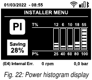
PI: Power histogram
A histogram of the power delivered is displayed on 5 vertical bars. The histogram indicates how long the pump has been on at a given power level. On the horizontal axis are the bars at the various power levels; on the vertical axis, the time for which the pump has been on at the specific power level (% of the time with respect to the total).
Multi-pump system
Displays the system status when in the presence of a multi-pump installation. If communication is not present, an icon depicting communication absent or interrupted is displayed. If there are several devices connected to one another, an icon is shown for each of them. The icon has the symbol of a pump under which are characters indicating the pump status. Depending on the operating status it will display as in table below.
Table 10: View of the multi-pump system
| System display | ||
| Status | Icon | Status information under the icon |
| Motor running | Symbol of pump turning | Speed in three figures |
| Motor stopped | Symbol of static pump | SB |
| Device faulty | Symbol of static pump | F |
If the device is configured as reserve the icon depicting the pump is dark in colour, the display remains similar to Table 5 with the exception that, if the motor is stopped, it shows F instead of SB.
Output flow meter
The page shows two flow meters. The first shows the total output flow delivered by the machine. The second shows a partial count and can be reset by the user. The partial count can be reset from this page, by holding down the button for 2 sec.
NT: Display of network configuration
Information on network and serial connectors. The serial connector can be displayed in full by pressing the key.
VE: Version display
Information on the hardware version, serial number and mac address of the pump. L'intero seriale può essere visualizzato tenendo premuto il tasto per 4 sec.
FF: Fault & Warning display (Log)
Chronological display of the faults that have occurred during system operation. Under the symbol FF appear two numbers x/y indicating respectively the ault displayed and the total number of faults present; to the right of these numbers is an indication of the type of fault displayed. The and keys scroll through the list of faults: pressing the key goes back through the log and stops at the oldest fault present, pressing the key goes forward in the log and stops at the most recent fault. The faults are displayed in chronological order starting from the one that appeared farthest back in time x=1 to the most recent x=y. The maximum number of faults that can be shown is 64; when that number is reached, the log starts to overwrite the oldest ones. This item on the menu displays the list of faults, but does not allow reset. Reset can be carried out only with the dedicated control from item RF on the TECHNICAL ASSISTANCE MENU. The fault log cannot be deleted with a manual reset, by switching off the appliance, or by resetting the factory values, unless the procedure described above has been followed.
Monitor Menu
From the main menu, by holding down simultaneously for 2 sec the keys and , or using the selection menu and pressing or , you can access the MONITOR MENU. In this menu, by pressing the , key, the following values are displayed in sequence.
BK: Display brightness
Adjusts the backlighting of the display on a scale from 0 to 100.
TK: Backlight switch-on time
Sets the time that the backlight is lit since the last time a key was pressed. Values allowed: 20 sec to 10 min or always on (even if this option is selected, the screen will still go into standby mode after a few hours of inactivity to safeguard the integrity of the device). When the backlight is off, the first time any key is pressed has the sole effect of restoring the backlighting.
LA: Language
Display in one of the following languages:
- Italian
- English
- German
- Spanish
- Dutch
- Swedish
- Turkish
- Romanian
- Czech
- Polish
- Russian
- Portoguese
- Thai
- French
- Slovak
- Chinese
- Arabic
Once you have selected your preferred language, the system will adopt it when moving to the next menu item.
TE: Dissipator temperature display
Shows the dissipator temperature display.
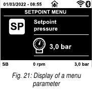
Setpoint Menu
From the main menu, hold down simultaneously the and keys until "SP" appears on the display (or use the selection menu pressing or ). The and keys allow you respectively to increase and decrease the plant boosting pressure. Press to leave this menu and return to the main menu.
SP: Setting the setpoint pressure
Pressure at which the system is pressurised: min 1 bar (14 psi) – max 6 bar (87 psi) and there are no auxiliary pressure control functions.
![]() If several auxiliary pressure functions associated with several inputs are active at the same time, the device will set the lowest pressure of all the active ones.
If several auxiliary pressure functions associated with several inputs are active at the same time, the device will set the lowest pressure of all the active ones.
![]() The auxiliary setpoints can be used only through the control unit.
The auxiliary setpoints can be used only through the control unit.
Setting the auxiliary pressures
The device has the possibility of varying the setpoint pressure according to the status of the inputs, up to 4 auxiliary pressures can be set for a total of 5 different setpoints. For the electrical connections refer to the control unit manual; for the software settings see paragraph Setup of the auxiliary digitali inputs IN1, IN2, IN3, IN4.
P1: Setting the auxiliary setpoint 1
Pressure at which the system is pressurised if the auxiliary setpoint function is activated on input 1.
P2: Setting the auxiliary setpoint 2
Pressure at which the system is pressurised if the auxiliary setpoint function is activated on input 2.
P3: Setting the auxiliary setpoint 3
Pressure at which the system is pressurised if the auxiliary setpoint function is activated on input 3.
P4: Setting the auxiliary setpoint 4
Pressure at which the system is pressurised if the auxiliary setpoint function is activated on input 4.
![]() The pump restarting pressure is linked not only to the set pressure SP but also to RP. RP expresses the decrease in pressure, with respect to "SP" caused by the pump starting.
The pump restarting pressure is linked not only to the set pressure SP but also to RP. RP expresses the decrease in pressure, with respect to "SP" caused by the pump starting.
For example: SP = 3,0 [bar]; RP = 0,5 [bar]; no active auxiliary setpoint function: During normal operation the system is pressurised at 3,0 [bar]. The electropump restarts when the pressure falls below 2,7 [bar].
![]() Setting a pressure (SP, P1, P2, P3, P4) that is too high for the pump performance may cause false water lack errors BL; in these cases lower the set pressure.
Setting a pressure (SP, P1, P2, P3, P4) that is too high for the pump performance may cause false water lack errors BL; in these cases lower the set pressure.
Manual Menu
In manual operation, the sum of the input pressure and the maximum pressure that can be supplied must not be greater than 6 bar.
From the main menu, hold down simultaneously the and and keys until the manual menu page appears (or use the selection menu pressing or ). The menu allows you to view and modify various configuration parameters: the ey allows you to scroll through the menu pages, the and keys allow you respectively to increase and decrease the value of the parameter concerned. Press leave this menu and return to the main menu. Entering the manual menu by pressing the  keys puts the machine into forced STOP condition. This function can be used to force the machine to stop. In the main menu, irrespective of the parameter displayed, it is always possible to perform the following controls:
- Temporary starting of the electropump.
Pressing the![]() and
and ![]() keys at the same time causes the pump to start at speed RI and this running status remains as long as the two keys are held down. When the pump ON of pump OFF command is given, a communication appears on the display.
keys at the same time causes the pump to start at speed RI and this running status remains as long as the two keys are held down. When the pump ON of pump OFF command is given, a communication appears on the display. - Starting the pump.
- Holding down the
![]() and
and ![]() keys simultaneously for 2 sec. causes the pump to start at speed RI. L The running status remains until the
keys simultaneously for 2 sec. causes the pump to start at speed RI. L The running status remains until the ![]() key is pressed. The next time the
key is pressed. The next time the ![]() key is pressed the pump leaves the manual menu. When the pump ON of pump OFF command is given, a communication appears on the display. In case of operation in this mode for more than 5' with no flow of liquid, an alarm overheating alarm will be triggered, with the error PH shown on the display. Once the PH error condition is no longer present, the alarm will be reset automatically only. The reset time is 15'; if the PH error occurs more than 6 times consecutively, the reset time increases to 1h. Once it has reset further to this error, the pump will remain in stop status until the user restarts it using the
key is pressed the pump leaves the manual menu. When the pump ON of pump OFF command is given, a communication appears on the display. In case of operation in this mode for more than 5' with no flow of liquid, an alarm overheating alarm will be triggered, with the error PH shown on the display. Once the PH error condition is no longer present, the alarm will be reset automatically only. The reset time is 15'; if the PH error occurs more than 6 times consecutively, the reset time increases to 1h. Once it has reset further to this error, the pump will remain in stop status until the user restarts it using the ![]() keys.
keys.
 and
and  keys.
keys.Status
Displays the pump status.
RI: Speed setting
Sets the motor speed in rpm. Allows you to force the number of revolutions at a predetermined value.
VP: Pressure display
Plant pressure measured in [bar] or [psi] depending on the measuring system used.
VF: Flow display
Displays the flow in the chosen unit of measure. The measuring unit may be l/min or gal/min see MS: Measuring system.
PO: Absorbed power display
Power absorbed by the electropump in kW.
A flashing round symbol may appear under the symbol of the measured power PO. This symbol indicates the pre-alarm for exceeding the allowed maximum power.
C1: Phase current display
Motor phase current in A.
If the maximum allowed current is exceeded, the identification C1 blinks, indicating an imminent tripping of the overload protection.
RS: Rotation speed display
Motor rotation speed in rpm.
TE: Dissipator temperature display
Shows the dissipator temperature display.
Installer Menu
From the main menu, hold down simultaneously the and and keys until the first parameter of the installer menu appears on the display (or use the selection menu pressing or . The menu allows you to view and modify various configuration parameters: the key allows you to scroll through the menu pages, the and keys allow you respectively to increase and decrease the value of the parameter concerned. Press to leave this menu and return to the main menu.
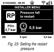
RP: Setting the pressure fall to restart
Expresses the fall in pressure with respect to the SP value which causes. Restarting of the pump. For example if the setpoint pressure is 3,0 bar and RP is 0,3 bar the pump will restart at 2,5 bar. RP can be set from a minimum of 0.1 to a maximum of 1 [bar]. In particular conditions (for example in the case of a setpoint lower than the RP) it may be limited automatically. To assist the user, on the RP setting page the actual restarting pressure also appears highlighted under the RP symbol.
OD: Type of plant
Possible values "Rigid" and "Elastic" referring to a rigid system and an elastic system. The device leaves the factory with mode "Rigid" suitable for the majority of systems. In the presence of swings in pressure that cannot be stabilised by adjusting the parameters GI and GP, change to mode "Elastic".

The regulating parameters GP and GI also change in the two configurations. In addition the GP and GI values set in mode "Rigid" are stored in a different memory from the GP and GI values set in mode "Elastic". So, for example, when passing to mode "Elastic", the GB value of mode "Rigid" is replaced by the GB value of mode "Elastic" but it is kept and will reappear again when returning to mode "Rigid". The same value shown on the display has a different weight in one mode or in the other because the control algorithm is different.
MS: Measuring system
Set the measuring system, choosing between metric and Anglo-American units. The quantities displayed are shown in Table 11.
![]() The flow in Anglo-American units (gal/min) is indicated adopting a conversion factor of 1 gal = 4.0 litres, corresponding to the metric gallon
The flow in Anglo-American units (gal/min) is indicated adopting a conversion factor of 1 gal = 4.0 litres, corresponding to the metric gallon
Table 11
| Units of measurement displayed | ||
| Quantity | Metric units | Anglo-American units |
| Pressure | Bar | psi |
| Temperature | °C | °F |
| Flow rate | l/min | gal/min |
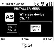
AS: Association of devices
Enables connection/disconnection mode with at the most 5 compatible elements:
- esy → Other Esybox pump for operation in a pump set composed of max 4 elements.
- DEV → Any other compatible devices
The icons of the various connected devices are displayed on page AS with below an identifying acronym and the respective reception power. An icon lit with a fixed light means that the device is connected and working correctly; a stroked through icon means the device is configured as part of the network but is not found.
![]() All the devices present on the airwaves are not displayed on this page but only the devices that have been associated with our network. Seeing only the devices in your own network allows the operation of several similar networks existing within the radius of action of the wireless without creating ambiguity; in this way the user does not see the elements that do not belong to his pumping system.
All the devices present on the airwaves are not displayed on this page but only the devices that have been associated with our network. Seeing only the devices in your own network allows the operation of several similar networks existing within the radius of action of the wireless without creating ambiguity; in this way the user does not see the elements that do not belong to his pumping system.
From this menu page it is possible to associate and disassociate an element from your personal wireless network. When the machine starts the AS menu item does not show any connection because no device is associated. In these conditions the message "No Dev" is shown and the COMM led is off. Only an action by the operator can allow devices to be added or removed with the operations of association and disassociation.
Association of devices
Once on the AS page, pressing for 5 sec puts the machine into wireless association search status, communicating this status with a flashing of the COMM led at regular intervals. As soon as two machines in a working communication range are put into this status, if possible, they are associated with each other. If the association is not possible for one or both machines, the procedure ends and a pop-up appears on each machine saying "association not possible". An association may not be possible because the device you are trying to associate is already present in the maximum number or because the device to be associated is not recognised. In the last case repeat the procedure from the start. The search status for association remains active until the device to be associated is detected (irrespective of the result of association); if no device can be seen within the space of 1 minute, the machine automatically leaves association status. You can leave the search status for wireless association at any time by pressing or . To speed up the procedure, a short-cut has been created that makes it possible to put the pump in association from the main page by pressing the key.
Once the association has been made between 2 or more devices, a pop-up appears on the display asking you to extend the configuration. This happens in the case where the devices have different configuration parameters (e.g. setpoint SP, RP etc.). Pressing on a pump extends the configuration of that pump to the other associated pumps. When the key is pressed, popups appear with the message "Wait...", and when this message is finished the pumps will start to work regularly with the sensitive parameters aligned; refer to paragraph Parameters concerning multipump per maggiori informazioni.
Disassociation of devices
To dissociate a device belonging to an existing group, go to page AS (installer menu) of the device itself and press the key for at least 5 seconds. After this operation all the icons related to the connected devices will be replaced by the message "No Dev" and the COMM LED will remain off.
Replacing devices
To replace a device in an existing group it is sufficient to dissociate the device to be replaced and to associate the new device as described in the procedures above. If it is not possible to dissociate the element to be replaced (faulty or not available), you will have to carry out the disassociation procedure for each device and create a new group.
PR: Remote pressure sensor
The PR parameter is used to select a remote pressure sensor.
The default setting is with no sensor present. In order to execute its intended functions, the remote sensor must be connected to a control unit, which in turn must be associated to the esybox, see point Operation with control unit.
As soon as a connection is established between the e.sybox and control unit and the remote pressure sensor has been connected, the sensor starts operating. When the sensor is active, the display shows an icon of a stylised sensor with a P inside it. The remote pressure sensor operates in synergy with the internal sensor so that the pressure never falls below the setpoint pressure in either of the two points in the system (internal and remote sensors). This allows compensation for any pressure drops.
NOTE: in order to maintain the setpoint pressure in the point with lower pressure, the pressure in the other point may be higher than the setpoint pressure.
T1: Low pressure delay  :
:
Sets the time when the inverter switches off after receiving the low pressure signal (see "Setting low pressure detection"). IThe low pressure signal can be received on each of the 4 inputs by suitably configuring the input (see Setup of the auxiliary digitali inputs IN1, IN2, IN3, IN4). T1 can be set between 0 and 12 s. The factory setting is 2 s.
EK : Setting the low pressure function on suction
Present only in models with Kiwa function. Sets the low pressure function on suction.
Table 12
| Value | Function |
| 0 | Disabled |
| 1 | Enabled with automatic reset |
| 2 | Enabled with manual reset |
PK : Low pressure threshold on suction
Present only in models with Kiwa function. Sets the pressure threshold below which the block is tripped for low pressure on suction.
 Parameters available in version KIWA
Technical Assistance Menu
Advanced settings to be made only by skilled personnel or under the direct control of the service network. From the main menu, hold down simultaneously the and and keys until "TB" appears on the display or ). The menu allows you to view and modify various configuration parameters: the ey allows you to scroll through the menu pages, the and keys allow you respectively to increase and decrease the value of the parameter concerned. Press to leave this menu and return to the main menu.
TB: Water lack blockage time
Setting the reaction time of the water lack blockage allows you to select the time (in seconds) taken by the device to indicate the lack of water. The variation of this parameter may be useful if there is known to be a delay between the moment the motor is switched on and the moment it actually begins to deliver. One example may be a plant where the suction pipe is particularly long and there are some slight leaks. In this case the pipe in question may be discharged and, even though water is not lacking, the electropump will take a certain time to reload, supply the flow and put the plant under pressure.
T2: Delay in switching off
Sets the delay with which the inverter must switch off after switch-off conditions have been reached: plant under pressure and flow rate lower than the minimum flow. T2 can be set between 2 and 120 s. The factory setting is 10 s.
GP: Proportional gain coefficient
Generally the proportional term must be increased for systems characterised by elasticity (for example with PVC pipes) and lowered in rigid systems (for example with iron pipes). To keep the pressure in the system constant, the inverter performs a type PI control on the measured pressure error. Depending on this error the inverter calculates the power to be supplied to the motor. The behaviour of this control depends on the set GP and GI parameters. To cope with the different behaviour of the various types of hydraulic plants where the system can work, the inverter allows the selection of parameters different from those set by the factory. For nearly all plants the factory-set GP and GI parameters are optimal. However, should any problems occur in adjustment, these settings may be varied.
GI: Integral gain coefficient
In the presence of large falls in pressure due to a sudden increase of the flow or a slow response of the system, increase the value of GI. Instead, if there are swings in pressure around the setpoint value, decrease the value of GI
To obtain satisfactory pressure adjustments, you generally have to adjust both GP and GI.
RM: Maximum speed
Sets a maximum limit on the number of pump revolutions.
Impostazione del numero di dispositivi e delle riserve
NC: Simultaneous devices
Sets the maximum number of devices that can work at the same time. It may have values between 1 and the number of devices present (max 4). By default NC assumes the number of active devices, which means that if active devices are added or removed, NC assumes the value of the devices present. Setting a value other than the active devices fixes the maximum number of simultaneous devices at the number set. This parameter is used in cases where there a limit on the pumps you can or want to be able to keep running (see IC: Configuration of the reserve and the examples below). On the same menu page you can also see (but not change) the other two system parameters linked to this: the number of devices present, detected automatically by the system, and the number of active devices.
IC: Configuration of the reserve
Configures the device as automatic or reserve. If set on auto (default) the device participates in normal pumping, if configured as reserve, minimum starting priority is associated with it, this means that the device with this setting will always start last. If a number of active devices is set that is one lower than the number of devices present and if one element is set as reserve, the effect obtained is that, if there are no problems, the reserve device does not participate in regular pumping; instead, if one of the devices that participates in pumping develops a fault (maybe loss of power supply, tripping of a protection, etc.), the reserve device will start.
The state of configuration as a reserve can be seen as follows: on the Multi-pump System page, the top of the icon is coloured; on the main page, the communication icon representing the address of the device appears with the number on a coloured background. There may be more than one device configured as reserve in a pumping system. Even though the devices configured as reserve do not participate in normal pumping, they are nevertheless kept efficient by the anti-stagnation algorithm. The anti-stagnation algorithm changes the starting priority once every 23 hours and allows the accumulation of at least one continuous minute of supply of flow from each device. The aim of this algorithm is to avoid the deterioration of the water inside the impeller and to keep the moving parts efficient; it is useful for all devices and especially for those configured as reserve, which do not work in normal conditions.
ET: Max. switching time
Sets the maximum continuous working time of a device in a set. It is significant only on pump sets with interconnected devices. The time can be set between 0 min and 9 hours; the factory setting is 2 hours. When the ET of a device has elapsed, the system starting order is reassigned so as to give minimum priority to the device on which the time has elapsed. The aim of this strategy is to use less the device that has already worked and to balance the working time between the various machines that make up the set. If the hydraulic load still requires the intervention of the device, even though it has been put last in starting order, it will start to guarantee pressure boosting of the system.
The starting priority is reassigned in two conditions based on the ET time:
- Exchange during pumping: when the pump remains on without interruption until the absolute maximum pumping time has been exceeded.
- Exchange to standby: when the pump is on standby but 50% of the ET time has been exceeded.
If ET has been set at 0 there will be exchange to standby. Whenever a pump in the set stops, a different pump will start first next time it is restarted.
![]() If the parameter ET (Max. switching time) is set at 0, there will be exchange at each restart, irrespective of the pump's actual work time.
If the parameter ET (Max. switching time) is set at 0, there will be exchange at each restart, irrespective of the pump's actual work time.
Examples of configuration for multipump systems
Example 1:
A pump set consisting of 2 devices (N=2 automatically detected), 2 of which are set automatically (factory settings: IC = automatic) and a contemporaneity index of N (factory settings: NC=number of devices). The effect is as follows: the highest-priority device always starts first, and if the pressure achieved is too low, the second back-up device also starts. The operation of the 2 will take place on a rotating basis so as to respect the maximum exchange time (ET) of each in order to evenly balance the wear and tear on the devices.
Example 2:
A pump set consisting of 2 devices (N=2 automatically detected) of which 1 is set as automatic (IC = automatic on one device), 1 as reserve (IC = reserve on the other device) a simultaneity index of 1 (NC=1). The effect is as follows: the device not configured as a reserve will start and work by itself (even though it does not manage to bear the hydraulic load and the pressure achieved is too low). If it has a fault, the reserve device steps in.
Example 3:
A pump set consisting of 2 devices (N=2 automatically detected) of which 1 is set as automatic (IC = automatic on one device), 1 as reserve (IC = reserve on the other device) a simultaneity index of N (factory settings: NC=number of devices).
The effect is as follows: the device that is not configured as reserve always starts first, if the pressure detected is too low the second device, configured as reserve, also starts. In this way we always try to preserve the use of one device in particular (the one configured as reserve), but this may be useful in case of necessity when a greater hydraulic load occurs.
AY: Anti Cycling
As described in paragraph Anti-Cycling this function is for avoiding frequent switching on and off in the case of leaks in the system. The function can be enabled in 2 different modes, normal and smart. In normal mode the electronic control blocks the motor after N identical start/stop cycles. In smart mode it acts on the parameter RP to reduce the negative effects due to leaks. If set on "Disable", the function does not intervene.
AE: Enabling the anti-block function
This function is for avoiding mechanical blocks in the case of long inactivity; it acts by periodically rotating the pump. When the function is enabled, every 23 hours the pump performs an unblocking cycle lasting 1 min.
AF: Enabling the anti-freeze function
If this function is enabled the pump is automatically rotated when the temperature reaches values close to freezing point, in order to avoid breakages of the pump.
Setup of the auxiliary digital inputs IN1, IN2, IN3, IN4
This paragraph shows the functions and possible configurations of the inputs of the control unit, connected by wireless to the device, by means of the parameters I1, I2, I3, I4. For the electrical connections refer to the control unit manual. The inputs IN1..IN4 are all the same and all the functions can be associated with each of them. Parameters I1, I2, I3 and I4 are used to associate the function required to the corresponding input (IN1, IN2, IN3 and IN4.). Each function associated with the inputs is explained in greater detail below in this paragraph. Table 14 sums up the functions and the various configurations. The factory configurations can be seen in Table 13.
Table 13: Factory configurations of the inputs
| Factory configurations of the digital inputs IN1, IN2, IN3, IN4 | |
| Input | Value |
| 1 | 0 (disable) |
| 2 | 0 (disable) |
| 3 | 0 (disable) |
| 4 | 0 (disable) |
Table 14: Configurations of the digital inputs
| Table summarising the possible configurations of the digital inputs IN1, IN2, IN3, IN4 and their operation | ||
| Value | Function associated to input INx | Display of the active function associated with the input |
| 0 | Input functions disabled | |
| 1 | Water lack from external float (NO) | Float switch symbol (F1) |
| 2 | Water lack from external float (NC) | Float switch symbol (F1) |
| 3 | Auxiliary setpoint Pi (NO) for the input used | Px |
| 4 | Auxiliary setpoint Pi (NC) for the input used | Px |
| 5 | General disabling of motor by external signal (NO) | F3 |
| 6 | General disabling of motor by external signal (NC) | F3 |
| 7 | General disabling of motor by external signal (NO) + Reset of resettable blocks | F3 |
| 8 | General disabling of motor by external signal (NC) + Reset of resettable blocks | F3 |
| 9 | Reset of resettable blocks NO | |
| 10 | Low pressure signal input NO, automatic and manual reset | F4 |
| 11 | Low pressure signal input NC, automatic and manual reset | F4 |
| 12 | Low pressure input NO only manual reset | F4 |
| 13 | Low pressure input NC only manual reset | F4 |
Disabling the functions associated with the input
Setting 0 as the configuration value of an input, each function associated with the input will be disabled irrespective of the signal present on the input terminals.
Setting external float function
The external float can be connected to any input, for the electrical connections refer to the control unit manual. The float function is obtained setting one of the values in Table 15 on the parameter Ix, for the input to which the float has been connected.
The activation of the external float function generates the block of the system. The function is conceived for connecting the input to a signal arriving from a float which indicates lack of water. When this function is active the float switch symbol is shown on the main page. For the system to block and give the error signal F1, the input must be activated for at least 1 sec.
When it is in error condition F1, the input must have been deactivated for at least 30 sec before the system can be unblocked. The behaviour of the function is summed up in Table 15.
When several float functions are configured at the same time on different inputs, the system will indicate F1 when at least one function is activated and will remove the alarm when none is activated.
Table 15: External float function
| Behaviour of the external float function depending on INx and on the input | ||||
| Value of Parameter Ix | Input configuration | Input status | Operation | Shown on display |
| 1 | Active with high signal on input (NO) | Absent | Normal | None |
| Present | System block for water lack by external float | F1 | ||
| 2 | Active with low signal on input (NC) | Absent | System block for water lack by external float | F1 |
| Present | Normal | None | ||
Setting auxiliary setpoint input function
The signal that enables an auxiliary setpoint can be supplied on any of the 4 inputs (for the electrical connections, refer to the control unit manual). The auxiliary setpoint is obtained by setting the Ix parameter relating to the input on which the connection has been made, in accordance with Table 16. Example: to use Paux 2 set I2 on 3 or 4 and use input 2 on the control unit; in this condition, if input 2 is energized, pressure Paux 2 will be produced and the display will show P2. The auxiliary setpoint function modifies the system setpoint from pressure SP (see par. Setpoint Menu) to pressure Pi, where is represents the input used. In this way, as well as SP, four other pressures are available, P1, P2, P3, P4.
When this function is active the symbol Pi is shown in the STATUS line on the main page.
For the system to work with the auxiliary setpoint, the input must be active for at least 1sec. When you are working with the auxiliary setpoint, to return to working with setpoint SP, the input must not be active for at least 1 sec. The behaviour of the function is summed up in Table 16.
When several auxiliary setpoint functions are configured at the same time on different inputs, the system will show Pi when at least one function is activated. For simultaneous activations, the pressure achieved will be the lowest of those with the active input. The alarm is removed when no input is activated.
Table 16: Auxiliary setpoint
| Behaviour of the auxiliary setpoint function depending on Ix and on the input | ||||
| Value of Parameter Ix | Input configuration | Input status | Operation | Shown on display |
| 3 | Active with high signal on input (NO) | Absent | i-th auxiliary setpoint not active | None |
| Present | i-th auxiliary setpoint active | Px | ||
| 4 | Active with low signal on input (NC) | Absent | i-th auxiliary setpoint active | Px |
| Present | i-th auxiliary setpoint not active | None | ||
Setting system disabling and fault reset
The signal that enables the system can be supplied to any input (for the electrical connections refer to the control unit manual). The system disabling function is obtained by setting the parameter Ix, relating to the input to which the signal to be used to disable the system is connected, on one of the values shown in Table 17.
When the function is active, the system shuts down completely and the F3 symbol appears on the main page.
When several system disabling functions are configured at the same time on different inputs, the system will indicate F3 when at least one function is activated and will remove the alarm when none is activated. For the system to work with the disable function, the input must be active for at least 1 sec. When the system is disabled, for the function to be deactivated (re-enabling the system), the input must not be active for at least 1 sec. The behaviour of the function is summed up in Table 17.
When several disable functions are configured at the same time on different inputs, the system will show F3 when at least one function is activated. The alarm is removed when no input is activated. This function also allows the resetting of any faults present, see Table 17.
Table 17: Disabling system restore and fault
| Behaviour of the system disabling and fault reset function depending on Ix and on the input | ||||
| Value of Parameter Ix | Input configuration | Input status | Operation | Shown on display |
| 5 | Active with high signal on input (NO) | Absent | Motor enabled | None |
| Present | Motor disabled | F3 | ||
| 6 | Active with low signal on input (NC) | Absent | Motor disabled | F3 |
| Present | Motor enabled | None | ||
| 7 | Active with high signal on input (NO) | Absent | Motor enabled | None |
| Present | Motor disabled + fault reset | F3 | ||
| 8 | Active with low signal on input (NC) | Absent | Motor disabled + fault reset | F3 |
| Present | Motor enabled | None | ||
| 9 | Active with high signal on input (NO) | Absent | Motor enabled | None |
| Present | Fault reset | None | ||
Setup of the outputs OUT1, OUT2
This section shows the functions and possible configurations of outputs OUT1 and OUT2 of the I/O control unit, with wireless connection to the device, set by means of parameters O1 and O2. For the electrical connections, refer to the control unit manual. The factory configurations can be seen in Table 18.
Table 18: Factory configurations of the outputs
| Factory configurations of the outputs | |
| Output | Value |
| OUT 1 | 2 (fault NO closes) |
| OUT 2 | 2 (Pump running NO closes) |
O1: Setting output 1 function
Output 1 communicates an active alarm (it indicates that a system block has occurred). The output allows the use of a normally open clean contact. The values and functions indicated in Table 19 are associated with the parameter O1.
O2: Setting output 2 function
Output 2 communicates the motor running status. The output allows the use of a normally open clean contact. The values and functions indicated in Table 19 are associated with the parameter O2.
Table 19: Factory configurations of the outputs
| Configuration of the functions associated with the outputs | ||||
| Output configuration | OUT1 | OUT2 | ||
| Activation condition | Output contact status | Activation condition | Output contact status | |
| 0 | No associated function | Contact always open | No associated function | Contact always open |
| 1 | No associated function | Contact always closed | No associated function | Contact always closed |
| 2 | Presence of blocking errors | In the case of blocking errors the contact closes | Output activation in case of blocking errors | When the motor is running the contact closes |
| 3 | Presence of blocking errors | In the case of blocking errors the contact opens | Output activation in case of blocking errors | When the motor is running the contact opens |
Setting low pressure detection on suction 
(typically used in boosting systemsconnected to the water mains)
The low pressure detecting function generates the blocking of the system after the time T1 (see T1: Low pressure delay :).
When this function is active the symbol F4 is shown on the main page.
Tripping of this function causes the pump to cut out; it may be reset automatically or manually. The automatic reset requires that, to leave the error condition F4, the pressure must return to a value 0.3 bar higher than PK for at least 2 sec. To reset the cut-out in manual mode, press and then release the and keys simultaneously.
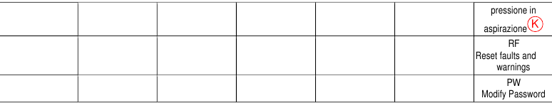
RF: Fault and warning reset
Holding down the and keys together for at least 2 seconds deletes the history of faults and warnings. The number of faults present in the log is indicated under the symbol RF (max 8). The log can be viewed from the MONITOR menu on page FF.
PW: Change password
The device has a password-enabled protection system. If a password is set, the parameters of the device will be accessible and visible but it will not be possible to change them.
When the password (PW) is "0" all the parameters are unlocked and can be edited. When a password is used (value of PW different from 0) all modifications are blocked and "XXXX" is displayed on the page PW.
If the password is set it allows to navigate through all the pages, but at any attempt to edit a parameter a pop-up appears, asking you to type in the password. When the correct password is typed in the parameters are unlocked and can be edited for 10' after the last key is pressed. If you want to cancel the password timer, just go to page PW and hold down and per 2 sec. together for 2". When the correct password is typed in a padlock is shown opening, while if the wrong password is given a flashing padlock appears. After resetting the factory values the password is set back at "0". Each change of the password takes effect when Mode or Set is pressed and each subsequent change of a parameter implies typing in the new password again (e.g. the installer makes all the settings with the default PW value = 0 and lastly sets the PW so as to be sure that the machine is already protected without any further action).
If the password is lost there are 2 possibilities for editing the parameters of the device:
- Make a note of the values of all the parameters, reset the device with the factory values, see paragraph Reset and factory settings. The reset operation cancels all the parameters of the device, including the password.
- Make a note of the number present on the password page, send a mail with this number to your service centre, in a few days you will be sent the password to unlock the device.
Password for multipump systems
When the PW is typed in to unlock a device in a set, all the devices are unlocked. When the PW is changed on a device in a set, all the devices receive the change. When activating protection with a PW on a device in a set ( and on page PW when PW≠0), the protection is activated on all the devices (to make any change you are asked for the PW).
Protection systems
The device is equipped with protection systems to preserve the pump, the motor, the supply line and the inverter. If one or more protections trip, the one with the highest priority is immediately notified on the display. Depending on the type of error the motor may stop, but when normal conditions are restored the error status may be cancelled immediately or only after a certain time, following an automatic reset. In the case of blockage due to water lack (BL), blockage due to motor overload (OC), blockage due to direct short circuit between the motor phases (SC), you can try to exit the error conditions manually by simultaneously pressing and releasing the and keys. If the error condition remains, you must take steps to eliminate the cause of the fault.
In the event of blocking due to one of the internal errors E18, E19, E20, E21 it is necessary to wait 15 minutes with the machine powered until the blocked status is automatically reset.
Table 20: Fault description
| Alarm in the fault log | |
| Display indication | Description |
| HL | Alarm giving advance warning of Hot Fluid Blockage |
| OT | Alarm giving advance warning of Blockage due to overheating of the power amplifiers |
| OBL | Alarm indicating abnormal temperature recorded on the Low Voltage board |
| AYS | "Anti Cycling Smart" function running |
| AE | "Anti Block" function running |
| AF | "Anti Freeze" function running |
| BAT | Low battery |
Table 21: Indications of blockages
| Blockage conditions | |
| Display indication | Description |
| PH | Cutout due to pump overheating |
| BL | Blockage due to water lack |
| BP1 | Blockage due to reading error on the delivery pressure sensor |
| BP2 | Blockage due to reading error on the suction pressure sensor |
| PB | Blockage due to supply voltage outside specifications |
| LP | Block for low DC voltage |
| HP | Block for high DC voltage |
| OT | Blockage due to overheating of the power stages |
| OC | Blockage due to motor overload |
| SC | Blockage due to short circuit between the motor phases |
| ESC | Blockage due to short circuit to earth |
| HL | Hot Fluid Blockage |
| NC | Blockage due to motor disconnected |
| Ei | Blockage due to i-th internal error |
| Vi | Blockage due to i-th internal voltage out of tolerance |
| EY | Block for cyclicality abnormal detected on the system |
 Parameters available in version KIWA
Description of blockages
"BL" Anti Dry-Run (Protection against dry running)
In the case of lack of water the pump is stopped automatically after the time TB. This is indicated by the red "Alarm" LED and by the letters "BL" on the display. After having restored the correct flow of water you can try to leave the protective block manually by pressing the and keys simultaneously and then releasing them. If the alarm status remains, or if the user does not intervene by restoring the flow of water and resetting the pump, the automatic restart will try to restart the pump.
If the parameter SP is not correctly set, the protection against water lack may not work correctly.
Anti-Cycling
(Protection against continuous cycles without utility request)
If there are leaks in the delivery section of the plant, the system starts and stops cyclically even if no water is intentionally being drawn: even just a slight leak (a few ml) can cause a fall in pressure which in turn starts the electropump.
The electronic control of the system is able to detect the presence of the leak, based on its recurrence.
The Anti-Cycling function can be excluded or activated in Basic or Smart mode.
In Basic mode, once the condition of recurrence is detected the pump stops and awaits manual reset. This condition is communicated to the user by the lighting of the red "Alarm" LED and the appearance of the word "ANTICYCLING" on the display. After the leak has been removed, you can manually force restart by simultaneously pressing and releasing the and keys. In Smart mode, once the leak condition is detected, the parameter RP is increased to decrease the number of starts over time.
Anti-Freeze
(Protection against freezing of water in the system)
The change of state of water from liquid to solid involves an increase in volume. It is therefore essential to ensure that the system does not remain full of water with temperatures close to freezing point, to avoid breakages of the system. This is the reason why it is recommended to empty any electropump that is going to remain unused during the winter. However, this system has a protection that prevents ice formation inside by activating the electropump when the temperature falls to values close to freezing point. In this way the water inside is heated and freezing prevented.
The Anti-Freeze protection only works if the system is electrically powered: if the plug is disconnected or in the absence of current the protection cannot work.
However, it is advised not to leave the system full during long periods of inactivity: drain the system properly through the drainage cap and put it away in a sheltered place.
Anti-lock: Protection against pump long blocking
See paragraph AE: Enabling the anti-block function.
"BP1" "BP2" Blockage due to fault of the pressure sensors
If the device detects a fault in one of the two suction pressure sensor the pump remains blocked and the error signal "BP1"for delivery pressure sensor and "BP2" for the suction pressure sensor is indicated respectively. The fault status begins as soon as the problem is detected and ends automatically when correct conditions have been restored.
"PB" Blockage due to supply voltage outside specifications
This occurs when the allowed line voltage at the supply terminal assumes values outside the specifications. It is reset only automatically when the voltage at the terminal returns within the allowed values.
"SC" Blockage due to short circuit between the motor phases
The device is provided with protection against the direct short circuit which may occur between the motor phases. When this blockage is indicated you can attempt to restore operation by simultaneously holding down the and keys, but this will not have any effect until 10 seconds have passed since the moment the short circuit occurred.
Manual reset of error conditions
In error status, the user can cancel the error by forcing a new attempt, pressing and then releasing the and keys.
Self-reset of error conditions
For some malfunctions and blockage conditions, the system attempts automatic self-reset.
The auto self-reset procedure concerns in particular:
"BL" Blockage due to water lack
"PB" Blockage due to line voltage outside specifications
"OT" Blockage due to overheating of the power stages
"OC" Blockage due to motor overload
"BP1" Blockage due to fault of the pressure sensor
"BP2" Blockage due to fault of the Kiwa pressure sensor
For example, if the system is blocked due to water lack, the device automatically starts a test procedure to check whether the machine is really left definitively and permanently dry. If during the sequence of operations an attempted reset is successful (for example, the water comes back), the procedure is interrupted and normal operation is resumed.
Table 13 shows the sequences of the operations performed by the device for the different types of blockage.
Table 22: Self-reset of blockages
| Automatic resets of error conditions | ||
| Display indication | Description | Automatic reset sequence |
| BL | Blockage due to water lack |
|
| PB | Blockage due to line voltage outside specifications |
|
| OT | Blockage due to overheating of the power stages |
|
| OC | Blockage due to motor overload |
|
Operation with control unit
The pump, alone or in a pumping unit, can be connected via radio communication to an external unit hereinafter referred to as the control unit. Depending on the model, the control unit offers various functions.
Possible control units are:
- Esy I/O
The combination of one or more pumps with a control unit allows you to use:
- Digital Inputs
- Relay outputs
- Remote Pressure Sensor
- Modbus communication protocol
In the following, we will indicate with the term control unit functionality, the set of functions listed above and made available by the various types of control unit
Functionality available from the control box
The available features are listed in the table below.
Table 23: Functionality available from the control box
| Feature | Esy I/O |
| Opto-isolated digital inputs | • |
| Output relay with NO contact | • |
| Remote Pressure Sensor | • |
| Modbus | • |
Electrical connections to user inputs and outputs
See control unit manual.
Setting Functions from the Control Unit
The default value of all inputs and the remote pressure sensor is Disabled, so in order to use them, they must be activated by the user see chapter Setup of the auxiliary digitali inputs IN1, IN2, IN3, IN4 and PR: Remote pressure sensor.
Outputs are enabled by default, see chapter Setup of the outputs OUT1, OUT2.
If no control box has been associated, the input, output and remote pressure sensor functions are neglected and have no effect whatever their setting. The parameters related to the control unit (inputs, outputs and pressure sensor) can be set even if the connection is absent or even not made. If the control unit is associated (it is part of the pump's wireless network), but due to problems it is absent or not visible, when the parameters related to the functions are set to a value other than Disabled, they flash to indicate that they will not be able to perform their function.
Pairing and dissociating the pump with the control unit
To make the association between the pump and the control unit, proceed in the same way as for the association of a pump: from the AS page of the installer menu, press the key for 5 seconds until the blue LED does not start flashing (whether the pump is alone or in a group). Once this is done, on the control unit, Press the  key for 5 seconds until you hear a beep and the blue communication LED starts flashing. As soon as the connection has been established, the same LED remains lit steadily and the symbol of the control unit appears on the AS page of the pump. The dissociation of the control unit is similar to that of the pump: from the AS page of the installer menu, press the key for 5 seconds; this will delete all wireless connections that are present.
Reset and factory settings
General system reset
To reset the system, hold down the 4 keys simultaneously for 3 sec. This operation is the same as disconnecting the power, waiting for it to close down completely and supplying power again. The reset does not delete the settings saved by the user.
Factory settings
The device leaves the factory with a series of preset parameters which may be changed according to the user's requirements. Each change of the settings is automatically saved in the memory and, if desired, it is always possible to restore the factory conditions (see Restoring the factory settings par Restoring the factory settings).
Restoring the factory settings
To restore the factory values, switch off the device, wait until the display has switched off completely, press and hold down the and keys and turn on the power; release the two keys only when the letters "EE" appear. This restores the factory settings (a message and a rereading on EEPROM of the factory settings permanently saved in the FLASH memory). Once all the parameters have been set, the device returns to normal operation.
 Once the factory values have been restored it will be necessary to reset all the parameters that characterise the system (gains, setpoint pressure, etc.) as at the first installation
Table 24
| Factory settings | ||||
| Identifying code | Description | International factory settings | Angloamerican factory settings | Installation Memo |
| BK | Display brightness | 80%/50% | 80%/50% | |
| TK | Backlight lighting T | 2 min | 2 min | |
| LA | Language | English | English | |
| SP | Setpoint pressure | 2,7 bar | 39 psi | |
| RI | Revs per minute in manual mode | 3200 rpm | 3200 rpm | |
| OD | Type of plant | 1 (Rigid) | 1 (Rigid) | |
| RP | Pressure decrease to restart | 0,3 | 0,3 | |
| MS | Measuring system | 0 (International) | 0 (International) | |
| EK | Low pressure function on suction | 2 (Manual reset) | 2 (Manual reset) | |
| PK | Low pressure threshold on suction | 1,0 bar | 4 psi | |
| TB | Blockage time for water lack | 15 s | 15 s | |
| T1 | Low pr. delay | 2 s | 2 s | |
| T2 | Delay in switching off | 10 s | 10 s | |
| GP | Proportional gain coefficient | 0,5 | 0,5 | |
| GI | Integral gain coefficient | 1,2 | 1,2 | |
| RM | Maximum speed | 7000 rpm | 7000 rpm | |
| IC | Configuration of the reserve | 1 (Auto) | 1 (Auto) | |
| ET | Max. exchange time [h] | 2 | 2 | |
| AE | Anti-blocking function | 1(Enable) | 1(Enable) | |
| AF | Antifreeze | 1(Enable) | 1(Enable) | |
| PW | Change Password | 0 | 0 | |
| AY | Anticycling Function | 0 (Disabled) | 0 (Disabled) | |
PARTICULAR INSTALLATIONS
Disabling self-priming
The product is made and supplied with the capacity of being self-priming. The system is able to prime and therefore operate in whatever installation configuration chosen: below head or above head. However there are cases in which the self-priming capacity is not necessary, or areas where it is forbidden to use self-priming pumps. During priming the pump obliges part of the water already under pressure to return to the suction part until a pressure value is reached at delivery whereby the system can be considered primed. At this point the recirculating channel closes automatically. This phase is repeated each time the pump is switched on, even already primed, until the same pressure value that closes the recirculating port is reached (about 1 bar).
When the water arrives at the system intake already under pressure (maximum allowed 2 bar) or when the installation is always below head, it is possible (and mandatory where local regulations require it) to force the closure of the recirculating port, losing the self-priming capacityThis gives the advantage of eliminating the clap-like noise of the pipe shutter each time the system is switched on.
To force closure of the self-priming pipe, proceed as follows:
- Disconnect the power supply;
- empty the system (unless you decide to inhibit self-priming at the first installation);
- remove the drainage cap on Face E, taking care not to drop the O-Ring;
![]()
- with the aid of pliers take the shutter out of its seat. The shutter will be extracted together with the O-Ring and the metal spring with which it is assembled;
![]()
- remove the spring from the shutter; insert the shutter in its seat again with the respective O-Ring (side with gasket towards the inside of the pump, stem with cross-shaped fins towards the outside);
![]()
- screw on the cap after having positioned the metal spring in side so that it is compressed between the cap itself and the with crossshaped fins of the shutter stem. When repositioning the cap ensure that the respective O-Ring is always correctly in its seat;
![]()
- fill the pump, connect the power supply, start the system.
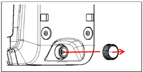
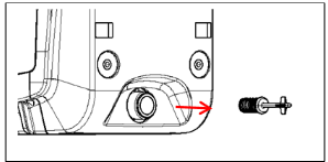
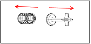
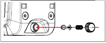
Installation with quick connection
DAB supplies an accessory kit for Quick Connection of the system. This is a quick coupling base on which to make the connections to the plant and from which the system can be simply connected or disconnected.
Advantages:
- possibility of making up the plant on-site, testing it, but removing the actual system until the moment of delivery, avoiding possible damage (accidental blows, dirt, theft, ...);
- it is easy for the Assistance service to replace the system with a "spare" in the event of special maintenance.
The system mounted on its quick connection interface appears as in Fig. 10.
![]()
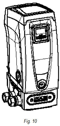
Multiple Sets
Introduction to multipump systems
By multipump systems we mean a pump set made up of a number of pumps whose deliveries all flow into a common manifold. The devices communicate with one another by means of the connection provided (wireless). The group may be made up of a maximum of 4 devices.
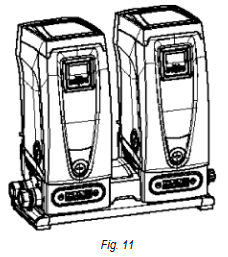
A multipump system is used mainly for:
- Increasing hydraulic performance in comparison with a single device.
- Ensuring continuity of operation in the event of a device developing a fault.
- Sharing out the maximum power.
Making a multipump system
The hydraulic plant must be created as symmetrically as possible to obtain a hydraulic load uniformly distributed over all the pumps. The pumps must all be connected to a single delivery manifold.
For good operation of the pressure boosting set, the following must be the same for each device:
- hydraulic connections,
- maximum speed (parameter RM)
The firmware of the connected Esybox Mini3 units must all be the same. Once the hydraulic system has been made, it is necessary to create the pumping set by carrying out the wireless association of the devices (see par Multiple Sets)
Wireless communication
The devices communicate with each other and send the flow and pressure signals by wireless communication.
Connection and setting of the photo-coupled inputs
The inputs of the I/O control unit are used to activate the float, auxiliary setpoint, system disabling and low suction pressure functions. The functions are indicated respectively by the float switch (F1), Px, F3 and F4 symbols. If activated, the Paux function boosts the pressure in the system to the set pressure see par. Setup of the auxiliary digitali inputs IN1, IN2, IN3, IN4. The functions F1, F3, F4 stop the pump for 3 different reasons, see par. Setup of the auxiliary digitali inputs IN1, IN2, IN3, IN4. The parameters for setting the inputs I1, I2, I3, I4 are part of the sensitive parameters, so setting one of these on any device means that they are automatically aligned on all the devices. Parameters linked to multipump operation.
The parameters shown on the menu for multipump operation are classified as follows:
- Read-only parameters..
- Parameters with local significance.
- Multipump system configuration parameters which in turn are divided into: Sensitive parameters/Parameters with optional alignment.
Parameters concerning multipump
The parameters shown on the menu for multipump operation are classified as follows:
- Read-only parameters.
- Parameters with local significance.
- Multipump system configuration parameters which in turn are divided into:
- Sensitive parameters
- Parameters with optional alignment
Parameters with local significance
These are parameters that can be divided among the various devices and in some cases it is necessary for them to be different. For these parameters it is not allowed to align the configuration automatically among the various devices. For example, in the case of manual assignment of the addresses, these must absolutely be different one from the other. List of parameters with local significance for the device.
- BK Brightness
- TK Backlight switch-on time
- RI Revs/min in manual mode
- IC Reserve configuration
- RF Reset fault and warning
Sensitive parameters
These are parameters which must necessarily be aligned over the whole chain for adjustment reasons.
List of sensitive parameters:
- SP Setpoint pressure
- P1 Auxiliary setpoint input 1
- P2 Auxiliary setpoint input 2
- P3 Auxiliary setpoint input 3
- P4 Auxiliary setpoint input 4
- RP Pressure decrease to restart
- ET Max. exchange time
- AY Anticycling
- NC Number of simultaneous devices
- TB Dry run time
- T1 Switch-off time after low pressure signal
- T2 Switch-off time
- GI Integral gain
- GP Proportional gain
- I1 Input 1 setting
- I2 Input 2 setting
- I3 Input 3 setting
- I4 Input 4 setting
- OD Type of system
- PR Remote pressure sensor
- PW Change password
Automatic alignment of sensitive parameters
When a multipump system is detected, the compatibility of the set parameters is checked. If the sensitive parameters are not aligned among all the devices, a message appears on the display of each device asking whether you want to propagate the configuration of that particular device to the whole system. If you accept, the sensitive parameters of the device on which you answered the question will be distributed to all the devices in the chain. If there are configurations that are not compatible with the system, these devices are not allowed to propagate their configuration. During normal operation, changing a sensitive parameter of a device results in the automatic alignment of the parameter on all the other devices without asking for confirmation.
The automatic alignment of the sensitive parameters has no effect on all the other types of parameters. In the particular case of inserting a device with factory settings in the chain (a device replacing an existing one or a device on which the factory configuration has been restored), if the present configurations with the exception of the factory configurations are compatible, the device with factory configuration automatically assumes the sensitive parameters of the chain
Parameters with optional alignment
These are parameters for which it is tolerated that they may not be aligned among the various devices. At each change of these parameters, when you press or , you are asked if you want to propagate the change to the entire communication chain. In this way, if all elements of the chain are the same, it avoids setting the same data on all the devices.
List of parameters with optional alignment:
- LA Language
- MS Measuring system
- AE Anti-blocking
- AF AntiFreeze
- O1 Function output 1
- O2 Function output 2
- RM Maximum speed
First start of the multipump system
Make the hydraulic and electrical connections of the whole system as described in chapter Plumbing and piping connection and Electrical connection. Switch on the devices and create the associations as described in paragraph AS: Association of devices.
Multipump adjustment
When a multipump system is switched on, the addresses are automatically assigned and an algorithm selects one device as the adjustment leader. The leader decides the speed and starting order of each device in the chain. The adjustment mode is sequential (the devices start one at a time). When starting conditions occur, the first device starts, when it has reached maximum speed the next one starts, and then the others in sequence. The starting order is not necessarily in ascending order according to the machine address, but it depends on the working hours done, see ET: Max. switching time.
Assigning the starting order
Each time the system is switched on a starting order is associated with each device. Depending on this, the sequential starts of the devices are decided. The starting order is modified during use as necessary by the following two algorithms.
- Reaching the maximum switching time.
- Reaching the maximum inactivity time
Maximum switching time
Depending on the parameter ET (maximum switching time), each device has a working time counter, and depending on this the starting order is updated with the following algorithm:
- if at least half of the ET value has been exceeded, the priority is exchanged the first time the inverter switches off (exchange to standby);
- if the ET value is reached without ever stopping, the inverter is switched off unconditionally and is taken to minimum restarting priority (exchange during running).
If the parameter ET (Max. switching time) is set at 0, there is an exchange at each restart. See ET: Max. switching time.
Reaching the maximum inactivity time
The multipump system has an anti-stagnation algorithm, the aim of which is to keep the pumps in perfect working order and to maintain the integrity of the pumped fluid. It works by allowing a rotation in the pumping order so as to make all the pumps supply at least one minute of flow every 23 hours. This happens whatever the device configuration (enabled or reserve). The exchange of priority requires that the device that has been stopped for 23 hours be given maximum priority in the starting order. This means that as soon as it is necessary to supply flow, it will be the first to start. The devices configured as reserve have precedence over the others. The algorithm ends its action when the device has supplied at least one minute of flow. When the intervention of the anti-stagnation algorithm is over, if the device is configured as reserve, it is returned to minimum priority to preserve it from wear.
Reserves and number of devices that participate in pumping
The multipump system reads how many elements are connected in communication and calls this number N. Then depending on the parameters: number of active devices and NC, it decides how many and which devices must work at a certain time.
NC represents the maximum number of devices that can work at the same time.
If there are a number of active devices in a chain and NC simultaneous devices, with NC smaller than the number of active devices, it means that at the most NC devices will start at the same time and that these devices will exchange with the number of active elements. If a device is configured with reserve preference, it will be the last in the starting order, so for example if there are 3 devices and one of these is configured as reserve, the reserve will be the third element to start, whereas if are set the number of active devices to 2, the reserve will not start unless one of the two active ones develops a fault.
See also the explanation of the parameters
NC: Simultaneous devices;
IC: Configuration of the reserve.
Wireless control
The device can be connected to other devices by means of the proprietary wireless channel. There is therefore the possibility of controlling particular operations of the system through signals received in remote mode: for example, depending on a tank level supplied by a float it is possible to order it to be filled; with the signal arriving from a timer it is possible to vary the setpoint from SP to P1 to supply irrigation.
These signals entering or leaving the system are managed by a control unit that can be bought separately from the DAB catalogue.
APP, CLOUD AND SOFTWARE UPDATE
Through the application H2D or through the service center, it is possible to update the software of the device to the latest version available. For pumping group operation it is necessary that all firmware versions are the same, so in case you are creating a group with one or more devices with different firmware versions, you will need to make an update to align all versions.
Requirements for APP H2D from Smartphone
- Android ≥ 8.
- IOS ≥ 12
- Internet access
PC Requirements for Access to the Cloud Dashboard.
- WEB browser that supports JavaScript (e.g. Microsoft Edge, Firefox, Google Chrome, Safari).
- Internet access
Internet Network Requirements for Access the Cloud
- Active and permanent direct connection to the Internet on site.
- Modem/Router WiFi.
- WiFi signal with good quality and strength in the area where the device is installed.
If the WiFi signal is deteriorated, the use of a WiFi Extender is suggested
The use of DHCP is recommended, although there is the option to set a Static IP
Firmware Update/Updates
Before you start using the device, make sure that the product is updated to the latest SW version available. Updates ensure better usability of the services offered by the product.
To get the most out of the product, also consult the online manual and watch the how-to videos. All the necessary information is available on the dabpumps.com website or on: Internetofpumps.com.
App download and installation
The product can be configured and monitored through a special app on the main stores.
If you have any doubts, access the internetofpumps.com website to be guided through the operation.
- Download the H2D APP from the Google Play Store for Android devices or the App Store for Apple devices.
download the app from http://internetofpumps.com
![]()


- Once downloaded, the icon associated with the H2D APP will appear on your device's screen.
- For optimal operation of the APP, accept the terms of use and all the permissions required to interact with the device itself.
- In order for the initial setup and/or registration to the cloud H2D desk and controller installation to be successful, you must carefully read and follow all instructions in the H2D APP.
H2D desk cloud Registration
If you do not already have a DAB account for H2D desk cloud, please register by clicking on the appropriate button. A valid e-mail address is required and you will receive the activation link to be confirmed.
Enter all mandatory data marked with an asterisk. Give consent to the privacy policy and fill in the required data.
Registration to the H2D desk cloud is free of charge and allows you to receive useful information for the use of DAB products.
Product Configuration
The product can be configured and monitored through a special app on the main stores. If you have any doubts, access the internetofpumps.com website to be guided through the operation.
The app guides the installer step-by-step through the first configuration and installation of the product. The app also allows you to update your product and enjoy DAB digital services. Refer to the H2D APP itself to complete the operation.
SPECIFIC CONFIGURATIONS
Vertical Configuration
Remove the 4 support feet from the bottom tray of the packaging and screw them fully into their brass seats. Put the system in place, taking into account the dimensions:
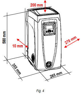
- The distance of at least 10 mm between Face E of the system and any wall is obligatory to ensure ventilation through the grids provided.
- The distance of at least 270 mm between Face B of the system and an obstruction is recommended so as to be able to carry out maintenance on the non-return valve without disconnecting the system.
- The distance of at least 200 mm between Face A of the system and an obstruction is recommended so as to be able to remove the door and gain access to the technical compartment.
If the surface is not flat, unscrew the foot that is not touching and adjust its height until it contacts the surface so as to ensure the stability of the system. The system must in fact be placed in a safe and stable position, ensuring that its axis is vertical: it must not be in an inclined position.
Installation "above head"
the vertical installation of the system is of the "over head" type, it is recommended to fit a non-return valve in the suction section of the system; this is to allow the operation of loading the system.
If the installation is of the "over head" type, install the suction pipe from the water source to the pump in such a way as to avoid the formation of goosenecks or siphons. Do not place the suction pipe above the pump level (to avoid the formation of air bubbles in the suction pipe). The suction pipe must draw at its entrance at a depth of at least 30cm below the water level and must be watertight along its whole length, as far as the entrance to the electropump. Access the technical compartment and, with the aid of the accessory tool or with a screwdriver, remove the filling cap. Fill the system with clean water through the loading door, taking care to let the air out. If the non-return valve on the suction pipe has been placed close to the system entry door, the quantity of water with which to fill the system should be 2.2 litres. It is recommended to fit the non-return valve at the end of the suction pipe (foot valve) so as to be able to fill it quickly too during the loading operation. In this case the quantity of water necessary for the loading operation will depend on the length of the suction pipe.
Installation "below head"
if there are no check valves between the water deposit and the system (or if they are open), it loads automatically as soon as it is allowed to let out the trapped air. So slackening the filling cap enough to vent the trapped air allows the system to load completely. You must survey the operation and close the loading door as soon as the water comes out (however it is recommended to fit a check valve in the section of the suction pipe and to use it to control the loading operation with the cap open). Alternatively, in the case where the suction pipe is intercepted by a closed valve, the loading operation may be carried out in a similar way to the one described for installation over head.
Horizontal Configuration
Remove the 4 support feet from the bottom tray of the packaging and screw them fully into their brass seats. Put the system in place, taking into account the dimensions:
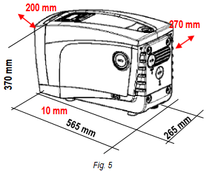
- The distance of at least 270 mm between Face B of the system and an obstruction is recommended so as to be able to carry out maintenance on the non-return valve without disconnecting the system.
- The distance of at least 200 mm between Face A of the system and an obstruction is recommended so as to be able to remove the door and gain access to the technical compartment.
- The distance of at least 10 mm between Face D of the system and an obstruction is obligatory to let out the power supply cable.
If the surface is not flat, unscrew the foot that is not touching and adjust its height until it contacts the surface so as to ensure the stability of the system. The system must in fact be placed in a safe and stable position, ensuring that its axis is vertical: it must not be in an inclined position.
In this configuration either of the 2 mouths can be used as an alternative to the other (depending on the convenience of the installation), or simultaneously (dual delivery system). So remove the cap(s) from the door(s) you intend to use with the aid of the accessory tool or with a screwdriver.
Installation "above head"
With the help of a screwdriver, remove the filler cap which, through the loading door, fill the system with clean water, taking care to let the air out: to ensure optimal filling, it is convenient to also open the loading door on the top of the product, used for filling in a vertical configuration, in order to completely drain all the air that could otherwise be trapped inside the system. Take care to close the openings correctly once you have finished the operation. It is recommended to set up a non-return valve at the end of the suction hose (foot valve) so that this can also be completely filled during the loading operation. In this case, the amount of water required for the loading operation will depend on the length of the suction hose.
Installation "below head"
If there are no shut-off valves between the water tank and the system (or they are open), the system automatically charges as soon as it is allowed to release the trapped air. Then, loosening the filler cap until the air vents allows the system to fully charge. The operation must be monitored and the loading door must be closed as soon as the water comes out.
Alternatively, if the intake duct is intercepted by a closed valve, the loading operation can be carried out in a manner similar to that described for the overhead installation.
ACCESSORY TOOL
DAB supplies the product with one or more accessory tools (e.g. keys, other, etc.) useful for carrying out the operations on the system required during installation and any extraordinary maintenance operations.
Accessory tools are used for:
- Opening and closing Dock (if any)
- NRV removal
- Cap manoeuvring
- Orientation of the interface panel (when provided for in chapter Control panel orientation) or to open the compartment door next to the interface panel itself.
Once the key has been used, store the key and/or any of its components in the compartment provided. See Fig. 2.
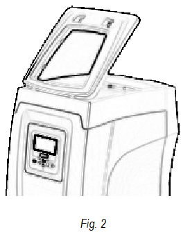
In the event that the key is lost or damaged, the operation can be carried out using the most appropriate tool according to the type of product: a standard hex wrench, a socket wrench, a flat-blade screwdriver, a cross-blade screwdriver.
Esybox Specifications
The tool is housed in the technical compartment. It is composed of 3 keys (Fig. 12):

- metal key with a hexagonal section;
- flat plastic key;
- cylindrical plastic key.
Key "1" is in turn inserted in the end "D" of key "3". At the first use you must separate the 2 plastic keys "2" and "3", which are supplied joined by a bridge (Fig. 12): break the bridge "A", taking care to remove the cutting residue from the 2 keys so as not to leave any sharp bits that could cause injuries.
Use the key "1" for the orientation of the interface panel as described in par.
Control panel orientation. the key is lost or damaged, the operation can be done using a standard 2 mm allen wrench (Fig. 14)
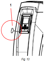
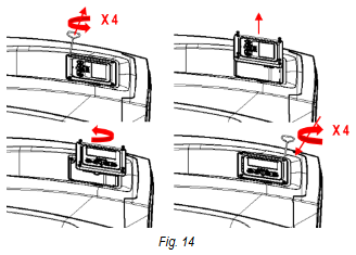
Once the 2 plastic keys have been separated they can be used by inserting "2" in one of the holes "B" in key "3": whichever hole is most convenient, depending on the operation. At this point you obtain a multifunction cross key, with a use corresponding to each of the 4 ends.
To use the cross key you must put the unused key "1" away in a safe place so that it does not get lost, or else put it back in its seat inside key "3" at the end of operations.
Use of end "C": (Fig. 16) this is practically a straight tip screwdriver of the correct size for manoeuvring the caps of the main connections of the system (1" and 1"1/4).
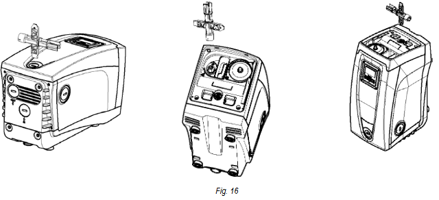
To be used at the first installation to remove the caps from the mouths on which you want to connect the system; for the filling operation in the case of horizontal installation; to access the non-return valve, ... If the key is lost or damaged, the same operations can be performed using a straight tip screwdriver of a suitable size.
Use of end "D": (Fig. 16) hexagonal socket head suitable for removing the cap to perform filling in the case of vertical installation. If the key is lost or damaged, the same.
Use of end "E": (Fig. 16) this is practically a straight tip screwdriver of the correct size for manoeuvring the motor shaft access cap and, if the interface for quick connection of the system has been installed (par. Multiple Sets), for access to the key for disengaging the connection. If the key is lost or damaged, the same operations can be performed using a straight tip screwdriver of a suitable size.
Use of end "F": (Fig. 16) the function of this tool is dedicated to maintenance of the non-return valve and it is better described in the respective paragraph NON-RETURN VALVE.
EXPANSION VESSEL
The system is complete with an integrated expansion vessel with a total capacity of 2 litres.
The main functions of the expansion vessel are:
- to make the system elastic so as to protect it against water hammer;
- to ensure a water reserve which, in the case of small leaks, maintains the pressure in the system for a longer time and spreads out needless
- restarts of the system which otherwise would be continuous; when the utility is turned on, ensure the water pressure for the seconds that the system takes to switch on and reach the correct rotation speed.
It is not a function of the integrated expansion vessel to ensure a water reserve such as to reduce interventions of the system (requests from the utility, not from a leak in the system). It is possible to add an expansion vessel with the capacity you prefer to the system, connecting it to a point on the delivery system (not a suction point). In the case of horizontal installation it is possible to connect to the unused delivery outlet. When choosing the tank, consider that the quantity of water released will also depend on the parameters SP and RP that can be set on the system. The expansion vessel is preloaded with pressurised air through the valve accessible from the technical compartmen (Fig. 3).
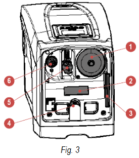
The preload value with which the expansion vessel is supplied by the manufacturer is in agreement with the parameters SP and RP set as default, and anyway it satisfies the following equation:
P_AIR = SP – RP – 0.7 Bar
Where:
- P_AIR: air pressure value in bar;
- SP = Set Point (Par. 3.0) in bar
- RP = Reduction of pressure to restart (Par. 0.3) in bar
So, by the manufacturer:
P_AIR = P_AIR = 3.0 - 0.3 - 0.7 = 2.7 Bar
If different values are set for the parameters SP and/or RP, regulate the valve of the expansion vessel releasing or letting in air until the above equation is satisfied again (e.g.: SP=2.0bar; RP=0.3bar; release air from the expansion vessel until a pressure of 1.0 bar is reached on the valve).
Failure to respect the above equation may lead to malfunctions of the system or to premature breakage of the diaphragm inside the expansion vessel. Considering the expansion vessel capacity of only 2 litres, any operation to check the air pressure must be performed by connecting the pressure gauge very rapidly: on small volumes the loss of even a limited quantity of air can cause an appreciable drop in pressure.
The quality of the expansion vessel ensures the maintenance of the set air pressure value, proceed to check it only at calibration or if you are sure of a malfunction. Any operation to check and/or reset the air pressure must be performed with the delivery system not under pressure: disconnect the pump from the power supply and open the utility nearest to the pump, keeping it open until it no longer gives any water. The special structure of the expansion vessel ensures its quantity and duration over time, especially of the diaphragm which is typically the component subject to wear for items of this type. However, in the case of breakage, the entire expansion vessel must be replaced and exclusively by authorised personnel.
Expansion vessel maintenance
See paragraph EXPANSION VESSEL for the operations to check and adjust the air pressure in the expansion vessel and to replace it if it is broken. To access the valve of the expansion vessel, proceed as follows:
- remove the access door to the special maintenance compartment (Fig. 1) disengaging the 2 fixing screws with the accessory tool. It is advisable not to remove the screws completely, so that you can used them to extract the door. Take care not to drop the screws inside the system once you have removed the door (Fig. 14);
- slip the rubber cap off the valve or the expansion vessel;
- regulate the valve;
- reposition the rubber cap;
- reposition the door and tighten the 2 screws.
MOTOR SHAFT
The electronic control of the system ensures smooth starts so as to avoid excessive stress on the mechanical parts and thus prolong the life of the product. In exceptional cases this characteristic could cause problems in starting the pump: after a period of inactivity, perhaps with the system drained, the salts dissolved in the water could have settled and formed calcification between the moving part (motor shaft) and the fixed part of the pump, thus increasing the resistance on starting. In this case it may be sufficient to help the motor shaft by hand to detach itself from the calcifications. In this system the operation is possible because access to the motor shaft from outside is guaranteed and a groove is provided at the end of the shaft. Proceed as follows:
- remove the motor shaft access cap;
- insert a straight tip screwdriver in the groove on the motor shaft and manoeuvre, turning in 2 directions;
- if it turns freely, the system can be started;
- if rotation is blocked it cannot be removed by hand, call the assistance service.
NON-RETURN VALVE
The system has an integrated non-return valve which is necessary for correct operation. The presence of solid bodies or sand in the water could cause malfunctioning of the valve and therefore of the system. Although it is recommended to use fresh water and eventually fit filters on input, if you notice abnormal operation of the non-return valve it can be extracted from the system and cleaned and/or replaced by proceeding as follows:

- Disconnect power supply;
- Empty the system;
- Remove screws if any;
- With the use of the accessory tool (or with pliers) remove the cap;
- Pull out the valve
- Clean the valve under running water, make sure it is not damaged and replace it if necessary;
Due to the cartridge remaining in its seat for a long time and/or to the presence of sediment, the force needed to extract the cartridge might be such as to damage the accessory tool. In this case it is intentional, because it is preferable to damage the tool rather than the cartridge. If the key is lost or damaged, the same operation can be performed with pliers.
Should one or more O-rings be lost or damaged during maintenance operations on the non-return valve, they must be replaced. Otherwise the system might not work correctly.
TROUBLESHOOTING
Before starting to look for faults it is necessary to disconnect the power supply to the pump.
| Fault | LED | Probable Causes | Remedies |
| The pump does not start. | Red: off White: off Blue: off | No electric power | Check whether there is voltage in the socket and insert the plug again. |
| The pump does not start | Red: on White: on Blue: off | Shaft blocked | See paragraph MOTOR SHAFT (motor shaft maintenance). |
| The pump does not start. | Red: off White: on Blue: off | Utility at a level higher than the system restarting pressure level (par. DESCRIPTION OF CONTROL PANEL). | Increase the system restarting pressure level by increasing SP or decreasing RP. |
| The pump does not stop. | Red: off White: on Blue: off |
|
|
| Insufficient delivery | Red: off White: on Blue: off |
|
|
| The pump starts without utility request | Red: off White: on Blue: off |
|
|
| The water pressure when turning on the utility is not immediate | Red: off White: on Blue: off | Expansion vessel empty (insufficient air pressure) or has broken diaphragm | Check the air pressure through the valve in the technical compartment. If water comes out when checking, the vessel is broken: assistance service. Otherwise restore the air pressure according to the equation par. EXPANSION VESSEL. |
| When the utility is turned on the flow falls to zero before the pump starts | Red: off White: on Blue: off | Air pressure in the expansion vessel higher than the system starting pressure | Calibrate the expansion vessel pressure or configure the parameters SP and/or RP so as to satisfy the equation (par. EXPANSION VESSEL). |
Troubleshooting for Embedded Electronics
Before starting to look for faults it is necessary to disconnect the power supply to the pump.
| Fault | LED | Probable Causes | Remedies |
| The display shows BL | Red: on White: on Blue: off |
|
|
| The display shows BP1 | Red: on White: on Blue: off | Faulty pressure sensor | Contact the assistance centre |
| The display shows BP2 | Red: on White: on Blue: off | Faulty pressure sensor | Contact the assistance centre |
| The display shows OC | Red: on White: on Blue: off |
|
|
| The display shows PB | Red: on White: on Blue: off |
|
|
| The display shows: Press to propagate this config | Red: off White: on Blue: off | One or more devices have sensitive parameters not aligned. | Press the key on the device which we are sure has the most recent and correct configuration of the parameters. |
WARNINGS AND RESIDUAL RISKS
Check that all the internal parts of the panel (components, leads, etc.) are completely free from traces of humidity, oxide or dirt: if necessary, clean accurately and check the efficiency of all the components in the panel. If necessary, replace any parts that are not perfectly efficient.
Before working on the electrical or mechanical part of the system, always disconnect the mains voltage. Wait for the indicator lights on the control panel to go out before opening the appliance. The DC intermediate circuit capacitor remains charged with dangerously high voltage even after the mains voltage is switched off. Only firmly wired network connections are permitted. The appliance must be earthed (IEC 536 class 1, NEC and other relevant standards).
Before working on the equipment, disconnect the power supply and make sure that there are no leaks of fluids and/or gases in the surrounding environment. Do not open or operate in the presence of voltage.
![]() Some functions might not be available, depending on the software version.
Some functions might not be available, depending on the software version.
Optional anti-impurity filter
If you are not sure that there are no foreign bodies in the water to be pumped, install a filter at the inlet of the system that is suitable for stopping impurities.
![]() The installation of a suction filter leads to a decrease in the hydraulic performance of the system proportional to the pressure drop induced by the filter itself (generally the greater the filtering power, the greater the drop in performance).
The installation of a suction filter leads to a decrease in the hydraulic performance of the system proportional to the pressure drop induced by the filter itself (generally the greater the filtering power, the greater the drop in performance).
Misuse
The equipment is designed to be used only for the purposes described in the appropriate section of the manual (paragraph FIELD OF APPLICATION AND PUMPABLE LIQUIDS). Uses other than those described in this manual are to be considered improper and therefore do not comply with safety regulations.
 ATTENTION!
Improper use may result in personal injury, death and/or damage to equipment or systems.
Below are a number of possible misuses that may result in personal injury or damage to the machine or equipment, for which, DAB Pumps. S.p. A. is not liable and rejects any liability:
- Unauthorized modifications or substitutions of equipment parts;
- Failure to follow safety instructions;
- Failure to follow instructions regarding installation, use, operation, maintenance, repair, or when these operations are performed by unqualified personnel;
- Use of improper and incompatible materials or auxiliary equipment;
- Failure to comply with workplace safety rules or applicable legal regulations.
Live parts
Refer to the Safety Booklet included in the packaging.
Documents / Resources
References
DNA Pump Selector
Complete solutions for remote control | DAB DConnect
![www.apple.com]() App Store - Apple
App Store - Apple![play.google.com]() Google Play
Google Play
Download manual
Here you can download full pdf version of manual, it may contain additional safety instructions, warranty information, FCC rules, etc.
Advertisement


Need help?
Do you have a question about the ESYBOX and is the answer not in the manual?
Questions and answers