DAB ESYBOX Instruction For Installation And Maintenance
Hide thumbs
Also See for ESYBOX:
- Installation manual ,
- Instruction for installation and maintenance (888 pages) ,
- Important information manual (80 pages)

Subscribe to Our Youtube Channel
Related Manuals for DAB ESYBOX


Summary of Contents for DAB ESYBOX
- Page 1 ISTRUZIONI PER L'INSTALLAZIONE E LA MANUTENZIONE (IT) INSTRUCTIONS FOR INSTALLATION AND MAINTENANCE (EN)
- Page 2 ITALIANO Pag. ENGLISH Pag.
- Page 3 Fig. 1 Fig. 3 Fig. 2 200 mm 200 mm 270 mm 10 mm 10 mm Fig. 5 Fig. 4...
- Page 4 Fig. 6 Fig. 7 Fig. 8...
- Page 5 Fig. 9 Fig. 10 Fig. 12 Fig. 11 Fig. 14 Fig. 13...
- Page 6 Fig. 15 Fig. 16...
-
Page 7: Table Of Contents
ITALIANO LEGENDA ....................................3 1.1. Segnaletica di sicurezza ................................. 3 CAMPO DI APPLICAZIONE E LIQUIDI POMPABILI ......................... 3 GENERALITÀ ....................................3 3.1. Nome prodotto ..................................3 3.2. Classificazione secondo Reg. Europeo ..........................3 3.3. Descrizione ..................................... 3 3.4. Riferimenti specifici di prodotto............................... 4 AVVERTENZE E RISCHI RESIDUI ............................. - Page 8 Installazione sopra-battente ............................36 16.2.2. Installazione sotto-battente ............................36 UTENSILE ACCESSORIO ................................. 36 17.1. Specifiche Esybox ................................37 VASO DI ESPANSIONE ................................37 18.1. Manutenzione vaso di espansione ............................38 ALBERO MOTORE ..................................38 VALVOLA DI NON RITORNO ..............................38 RISOLUZIONE DEI PROBLEMI ..............................
-
Page 9: Legenda
Leggere attentamente le istruzioni prima di operare o installare l'apparecchiatura. DAB Pumps compie ogni ragionevole sforzo affinché i contenuti del presente manuale (es. illustrazioni, testi e dati) siano accurati, corretti e attuali. Nonostante questo, potrebbero non essere privi di errori e potrebbero in ogni momento non risultare completi o aggiornati. -
Page 10: Riferimenti Specifici Di Prodotto
Di seguito sono riportate una serie di possibili usi impropri che possono provocare lesioni personali o danni alla macchina od alle attrezzature, per i quali, DAB Pumps. S.p.A. non risponde e respinge ogni responsabilità: Modifiche o sostituzioni di parti dell’attrezzatura non autorizzate;... -
Page 11: Trasporto
A monte ed a valle della pompa è consigliabile montare delle valvole di intercettazione in modo da evitare di dover svuotare l’impianto in caso di manutenzione alla pompa. Per il fissaggio a muro seguire le indicazioni di seguito riportate: Questo prodotto è già predisposto per poter essere installato anche sospeso a parete tramite Kit accessorio DAB da acquistare •... -
Page 12: Collegamento Elettrico
ITALIANO 6.3. Collegamento elettrico Attenzione: osservare sempre le norme di sicurezza! Nella rete di alimentazione deve essere previsto un dispositivo che assicuri la disconnessione completa nelle condizioni della categoria di sovratensioni III. Quando l’interruttore si trova in posizione aperta la distanza di separazione di ogni contatto deve rispettare quanto indicato nella tabella più... -
Page 13: Manutenzione
ITALIANO PERICOLO DI GELO: quando la pompa rimane inattiva per lungo tempo ad una temperatura inferiore a 0°C, è necessario procedere al completo svuotamento del corpo pompa attraverso il tappo di scarico, per evitare eventuali incrinature dei componenti idraulici. Tale operazione è... -
Page 14: Dichiarazione Di Conformità
Se il prodotto viene modificato in qualsiasi modo senza il nostro consenso, questa dichiarazione perderà la sua validità. 10. GARANZIA DAB si impegna affinché i suoi Prodotti siano conformi a quanto pattuito ed esenti da difetti e vizi originari connessi alla sua progettazione e/o fabbricazione tali da renderli non idonei all’uso al quale sono abitualmente preposti. -
Page 15: Dati Tecnici
ITALIANO SEZIONE APPENDICI 11. DATI TECNICI ESYBOX Tensione 1~ 220-240 V Frequenza 50/60 Hz Alimentazione elettrica Corrente massima 10 A Potenza massima 1550 W Corrente di dispersione verso terra < 2,5 mA Dimensioni di ingombro 565x265x352 mm senza piedi di appoggio... -
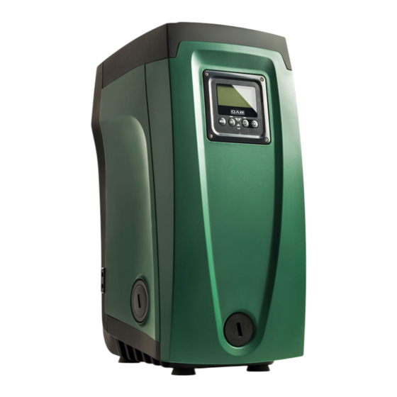
Page 16: Descrizione Del Pannello Di Controllo
ITALIANO 12. DESCRIZIONE DEL PANNELLO DI CONTROLLO Il controllo elettronico integrato nel sistema è del tipo ad Inverter e si avvale dell’utilizzo di sensori di flusso, di pressione e di temperatura anch’essi integrati nel sistema. Per mezzo di questi sensori il sistema si accende e si spenge automaticamente a seconda della necessità... -
Page 17: Funzionamento
ITALIANO 12.3. Funzionamento Una volta che l’elettropompa è adescata, il sistema inizia il suo funzionamento regolare secondo quelli che sono i parametri configurati: si avvia automaticamente all’apertura del rubinetto, fornisce acqua alla pressione impostata (SP), mantiene la pressione costante anche aprendo altri rubinetti, si arresta automaticamente dopo il tempo T2 una volta raggiunte le condizioni di spegnimento (T2 è... -
Page 18: Menu Ridotto
ITALIANO 13.1.1. Menu ridotto Menù ridotto ( visibile ) Menù esteso ( accesso diretto o password ) Menù Principale Menù Utente Menù Monitor Menù Setpoint Menù Manuale Menù Installatore Menù Ass. Tecnica MAIN STATO STATO (Pagina Principale) Retroilluminazione Pressione Diminuzione press. Tempo di blocco di setpoint per ripartenza... -
Page 19: Accesso Rapido
ITALIANO Funzione ingresso 4 Funzione uscita 1 Funzione uscita 2 Impostazione della rilevazione di bassa pressione in aspirazione Azzeramento fault & warning Modifica Password Tabella 5: Struttura dei menu 13.1.2. Accesso rapido Si accede direttamente al menù desiderato premendo contemporaneamente la combinazione di tasti per il tempo richiesto (ad esempio per entrare nel menù... -
Page 20: Struttura Delle Pagine Di Menù
ITALIANO compare nella selezione menù quando si usa una chiave di accesso. Nella Fig. 20 è mostrato uno schema del funzionamento per la selezione dei menù. Al centro della pagina si trovano i menù, dalla destra vi si arriva attraverso la selezione diretta con combinazione di tasti, dalla sinistra si arriva invece attraverso il sistema di selezione con menù... -
Page 21: Blocco Impostazione Parametri Tramite Password
ITALIANO Pagina Principale: Icone di Stato Stato Icona Descrizione Attivo Motore in marcia Fermo Motore fermo Disabilitato Motore disabilitato manualmente Errore bloccante: il tipo di errore è mostrato e descritto nell’angolo in basso a sinistra dello Errore schermo Errore Sensore Segnale di errore “Bassa pressione in aspirazione”... -
Page 22: Descrizione Dei Singoli Menu
ITALIANO 13.2. Descrizione dei singoli menu L’inverter fa lavorare il sistema a pressione costante. Questa regolazione viene apprezzata se l’impianto idraulico a valle del sistema è opportunamente dimensionato. Impianti eseguiti con tubazioni di sezione troppo piccola introducono delle perdite di carico che l’apparecchiatura non può compensare; il risultato è che la pressione è costante sui sensori ma non sull’utenza. Impianti eccessivamente deformabili possono creare l’insorgenza di oscillazioni;... -
Page 23: Menù Monitor
ITALIANO PI: Istogramma della potenza univoco attribuito per la connettività. L’intero seriale può essere Visualizza un istogramma della potenza erogata su 5 barre visualizzato tenendo premuto il tasto per 4 sec. verticali. L’istogramma indica per quanto tempo la pompa è stata accesa a un dato livello di potenza. -
Page 24: Menù Manuale
ITALIANO Impostazione delle pressioni ausiliarie Il dispositivo ha la possibilità di variare la pressione di setpoint in funzione dello stato degli ingressi, si possono impostare fino 4 pressione ausiliarie per un totale di 5 setpoint differenti. Per i collegamenti elettrici vedere il manuale della centralina di controllo. Per le impostazioni software vedere Setup degli ingressi digitali ausiliari IN1, IN2, IN3, IN4. -
Page 25: Menù Installatore
ITALIANO Stato C1: Visualizzazione della corrente di fase Visualizza lo stato della pompa Corrente di fase del motore in A. Sotto al simbolo della corrente di fase C1 può comparire un RI: Impostazione velocità simbolo circolare lampeggiante. Tale simbolo sta ad indicare il Imposta la velocità... - Page 26 Tabella 11 AS: Associazione dispositivi Permette di entrare in modalità connessione/disconnessione con al più 5 elementi compatibili: esy → Altra pompa Esybox per funzionamento in gruppo di pompaggio formato al max da 4 • elementi. DEV → Altri eventuali dispositivi compatibili •...
-
Page 27: Menù Assistenza Tecnica
Per assolvere alle proprie funzioni, Il sensore remoto va collegato ad una centralina di controllo e questa associata all’esybox, vedi Funzionamento con centralina di controllo e paragrafo 14.4.12 Controllo WireLess. Appena si è stabilito una connessione tra Esybox e centralina, ed il sensore di pressione remoto è stato connesso, il sensore inizia a lavorare. - Page 28 ITALIANO T2: Ritardo di spegnimento Imposta il ritardo con il quale si deve spegnere l’inverter da quando si sono raggiunte le condizioni di spegnimento: pressurizzazione dell’impianto e flusso è inferiore al flusso minimo. T2 può essere impostato tra 2 e 120 s. L’impostazione di fabbrica è di 10 s. GP: Coefficiente di guadagno proporzionale Il termine proporzionale in genere deve essere aumentato per sistemi caratterizzati da elasticità...
- Page 29 ITALIANO Nel caso in cui venga impostato ET uguale 0, si ha lo scambio allo standby. Ogni volta che una pompa del gruppo si ferma al successivo riavvio partirà un pompa diversa. Se il parametro ET (tempo massimo di scambio), è posto a 0, si ha lo scambio ad ogni ripartenza, indipendentemente dal tempo di lavoro effettivo della pompa.
- Page 30 ITALIANO Tabella riassuntiva delle possibili configurazioni degli ingressi digitali IN1, IN2, IN3, IN4 e del loro funzionamento Visualizzazione della Valore Funzione associata all’ingresso INx funzione attiva associata all’ingresso Funzioni ingresso disabilitate Mancanza acqua da galleggiante esterno (NO) Simbolo galleggiante (F1) Mancanza acqua da galleggiante esterno (NC) Simbolo galleggiante (F1) Setpoint ausiliario Pi (NO) relativo all’ingresso utilizzato...
- Page 31 ITALIANO Affinché il sistema lavori con setpoint ausiliario, l’ingresso deve essere attivo per almeno 1sec. Quando si sta lavorando con setpoint ausiliario, per tornare a lavorare con setpoint SP, l’ingresso deve non essere attivo per almeno 1sec. Il comportamento della funzione è riassunto in Tabella 16. Qualora siano configurate contemporaneamente più...
- Page 32 ITALIANO O1: Impostazione funzione uscita 1 L’uscita 1 comunica un allarme attivo (indica che è avvenuto un blocco del sistema). L’uscita consente l’utilizzo di un contatto pulito normalmente aperto. Al parametro O1 sono associati i valori e le funzionalità indicate in Tabella 19. O2: Impostazione funzione uscita 2 L’uscita 2 comunica lo stato di marcia del motore.
-
Page 33: Sistemi Di Protezione
ITALIANO Ogni cambiamento della password ha effetto alla pressione di Mode o Set ed ogni successiva modifica di un parametro implica il nuovo inserimento della nuova password (es. l’installatore fa tutte le impostazioni con il valore di PW default = 0 e per ultimo imposta la PW così... -
Page 34: Descrizione Dei Blocchi
ITALIANO 13.3.1. Descrizione dei blocchi “BL” Anti Dry-Run (Protezione contro la marcia a secco) Nella situazione di mancanza d’acqua la pompa viene arrestata automaticamente dopo il tempo TB. Questo viene indicato dal led rosso “Alarm” e dalla scritta “BL” sul display. Dopo aver ripristinato il corretto afflusso di acqua si può... -
Page 35: Auto Ripristino Delle Condizioni Di Errore
ITALIANO 13.3.9. Auto ripristino delle condizioni di errore Per alcuni malfunzionamenti e condizioni di blocco, il sistema esegue dei tentativi di ripristino automatico. Il sistema di auto ripristino riguarda in particolare: “BL” Blocco per mancanza acqua “OC” Blocco per sovracorrente nel motore “PB”... -
Page 36: Associazione E Dissociazione Della Pompa Con Centralina Di Controllo
ITALIANO Se non è stato associata nessuna centralina di controllo, le funzioni ingressi, uscite e sensore di pressione remoto, vengono trascurate e non hanno alcun effetto qualunque sia la loro impostazione. I parametri legati alla centralina di controllo (ingressi, uscite e sensore di pressione) possono essere impostati anche se la connessione è... -
Page 37: Installazioni Particolari
ITALIANO Funzione bassa 2 (Manuale) 2 (Manuale) pressione in aspirazione Soglia bassa pressione 1,0 bar 4 psi in aspirazione Tempo blocco 15 s 15 s mancanza acqua Ritardo bassa pr. Ritardo di spegnimento 10 s 10 s Coefficiente guadagno proporzionale Coefficiente guadagno integrale... -
Page 38: Installazione Con Connessione Rapida
14.2. Installazione con Connessione Rapida DAB fornisce un Kit accessorio per la Connessione Rapida del sistema. Si tratta di una base ad innesto rapido sulla quale realizzare le connessioni verso l’impianto e dalla quale poter connettere/disconnettere il sistema in maniera semplice. -
Page 39: Primo Avvio Sistema Multi Pompa
ITALIANO Parametri sensibili Sono dei parametri che devono necessariamente essere allineati su tutta la catena per ragioni di regolazione. Elenco dei parametri sensibili: SP Pressione di Setpoint T2 Tempo di spegnimento • • P1 Setpoint ausiliario ingresso 1 GI Guadagno integrale •... -
Page 40: Tempo Massimo Di Scambio
è possibile comandare il riempimento della stessa; con il segnale proveniente da un timer è possibile variare il set-point da SP a P1 per alimentare un’irrigazione. Questi segnali in ingresso o in uscita dal sistema, sono gestiti da una centralina di controllo acquistabile separatamente a catalogo DAB. 15. APP, CLOUD E AGGIORNAMENTO DEL SOFTWARE Attraverso l’App H2D oppure tramite centro servizi, è... -
Page 41: App Download E Installazione
Inserire tutti i dati obbligatori contraddistinti da un asterisco. Dare i consensi per la normativa della privacy e compilare i dati richiesti. La registrazione al cloud H2D desk è gratuita e consente di ricevere informazioni utili all’utilizzo dei prodotti DAB. -
Page 42: Installazione Sotto-Battente
17. UTENSILE ACCESSORIO DAB fornisce a corredo del prodotto uno o più utensili accessori (es: chiavi, altro..) utili per effettuare le operazioni sul sistema previste durante l’installazione ed eventuali operazioni di manutenzione straordinaria. -
Page 43: Specifiche Esybox
ITALIANO 17.1. Specifiche Esybox L’utensile trova alloggio nel vano tecnico. È composto da 3 chiavi (Fig. 12): chiave metallica a sezione esagonale; • chiave plastica piatta; • chiave plastica cilindrica. • La chiave “1” è a sua volta inserita nell’estremità “D” della chiave “3”. Al primo utilizzo occorre separare le 2 chiavi plastiche “2” e ”3”, che vengono fornite unite da un ponticello (Fig. -
Page 44: Manutenzione Vaso Di Espansione
ITALIANO Qualora si impostino valori diversi per i parametri SP e/o RP, agire sulla valvola del vaso di espansione rilasciando o immettendo aria fino a soddisfare nuovamente la relazione di cui sopra (es: SP = 2.0 bar RP = 0.3 bar, rilasciare aria dal vaso di espansione fino al raggiungimento della pressione di 1.0 bar sulla valvola). -
Page 45: Risoluzione Dei Problemi
ITALIANO Potrebbe succedere che a causa della lunga permanenza della valvola in sede e/o della presenza di sedimenti, la forza di estrazione della cartuccia sia tale da danneggiare l’utensile accessorio. Nel caso, la cosa è voluta in quanto è preferibile danneggiare l’utensile piuttosto che la cartuccia. Qualora la chiave venga perduta o danneggiata, la stessa operazione può... - Page 46 ITALIANO Anomalia Probabili Cause Rimedi Mancanza acqua. Adescare la pompa e verificare che non ci sia aria nella • • tubazione. Controllare che l’aspirazione o eventuali filtri Pompa non adescata. Rosso: acceso • Il display mostra non siano ostruiti. Bianco: acceso Setpoint non •...
- Page 47 ENGLISH KEY ......................................43 1.1. Safety Signs ..................................43 FIELD OF APPLICATION AND PUMPABLE LIQUIDS ......................43 GENERAL ....................................43 3.1. Product name ..................................43 3.2. Classification according to European Reg..........................43 3.3. Description.................................... 43 3.4. Specific product references ..............................44 WARNINGS AND RESIDUAL RISKS ............................
- Page 48 16.2.1. Installation “above head” ............................75 16.2.2. Installation “below head” ............................. 75 ACCESSORY TOOL .................................. 75 17.1. Esybox Specifications................................75 EXPANSION VESSEL ................................76 18.1. Expansion vessel maintenance ............................76 MOTOR SHAFT ..................................77 NON-RETURN VALVE................................77 TROUBLESHOOTING ................................77 21.1.
-
Page 49: Key
DAB Pumps makes every reasonable effort to ensure that the contents of this manual (e.g. illustrations, texts and data) are accurate, correct and up-to-date. Nevertheless, they may not be free of errors and may not be complete or up-to-date at any time. The company therefore reserves the right to make technical changes and improvements over time, even without prior notice. -
Page 50: Specific Product References
Improper use may result in personal injury, death and/or damage to equipment or systems. Below are a number of possible misuses that may result in personal injury or damage to the machine or equipment, for which, DAB Pumps. S.p.A. is not liable and rejects any liability: Unauthorized modifications or substitutions of equipment parts;... -
Page 51: Transport
Shut-off valves are to be mounted upstream and downstream of the pump in order to avoid having to empty the system in case of maintenance to the pump. For wall mounting, follow the instructions below: This product is already designed to be installed suspended on the wall using a DAB accessory kit to be purchased separately. •... -
Page 52: Commissioning
ENGLISH Make sure that the mains voltage corresponds to the CE marking voltage (technical plate) of the product. With the unit at full capacity, check that the current absorbed by the motor does not exceed that of the CE marking (technical plate). -
Page 53: Periodic Checks
8.4. CE marking and minimum instructions for DNA The image is for representative purposes only Consult the Product configurator (DNA) available on the DAB PUMPS website. The platform allows you to search for products by hydraulic performance, model or article number. Technical data sheets, spare parts, user manuals and other technical documentation can be obtained. -
Page 54: Guarantee
10. GUARANTEE DAB undertakes to ensure that its Products comply with what has been agreed and are free from original defects and faults connected with their design and/or manufacture that make them unsuitable for the use for which they are normally intended. -
Page 55: Technical Data
ENGLISH APPENDIX SECTION 11. TECHNICAL DATA ESYBOX Voltage 1~ 220-240 V Frequency 50/60 Hz Electric power supply Maximum current 10 A Maximum power 1550 W Leakage current to earth < 2,5 mA Overall dimensions 565x265x352 mm without feet Empty weight (excluding packaging) -
Page 56: Description Of Control Panel
ENGLISH 12. DESCRIPTION OF CONTROL PANEL The electronic control integrated in the system is of the type with inverter and it makes use of flow, pressure and temperature sensors, also integrated in the system. By means of these sensors the system switches on and off automatically according to the utility’s needs and it is able to detect conditions of malfunction, to prevent and indicate them. -
Page 57: Operation
ENGLISH 12.3. Operation Once the electropump is primed, the system starts regular operation according to the configured parameters: it starts automatically when the tap is turned on, supplies water at the set pressure (SP), keeps the pressure constant even when other taps are turned on, stops automatically after time T2 once the switching off conditions are reached (T2 can be set by the user). -
Page 58: Menu Structure
ENGLISH 13.1.1. Menu structure Reduced menu (visible) Extended menu (direct access or password) Main Menu User Menu Monitor Menu Setpoint Menu Manual Menu Installer Menu Tech.Assist. Menu MAIN STATUS STATUS (Main Page) Back lighting Setpoint pressure Decrease pressure Block time for water for restart lack Menu Selection... -
Page 59: Direct Access
ENGLISH pressione in aspirazione Reset faults and warnings Modify Password Table 5: Menu structure 13.1.2. Direct Access The desired menu can be accessed directly by pressing simultaneously the appropriate combination of keys for the required time (for example to enter the Setpoint menu) and the various items in the menu are scrolled with the key. -
Page 60: Structure Of The Menu
ENGLISH Fig. 20: Diagram of possible menu accesses 13.1.4. Structure of the menu pages When switched on, some presentation pages are displayed showing the name of the product and the logo, after which the main menu appears. The name of each menu, whichever it may be, is always at the top of the display. The following always appear on the main page: In the frame at the bottom of the screen, present on all pages, the Status Icons: description in Table 7... -
Page 61: Blocking Parameter Setting By Password
ENGLISH Disabled Motor manually disabled Error Blocking error: the type of error is shown and described in the bottom left corner of the screen KIWA Sensor Error “Low suction pressure” error signal Table 7: System Status Icons Main Page: Auxiliary Functions Icons Icon Description Power Shower... -
Page 62: User Menu
ENGLISH 13.2.1. User Menu From the main menu, pressing the key (or using the selection menu and pressing ), gives access to the USER MENU. In the menu the key allows you to scroll through the various menu pages. The values shown are the following. Status Multi-pump system Displays the pump status. -
Page 63: Monitor Menu
ENGLISH displayed in chronological order starting from the one that appeared farthest back in time x=1 to the most recent x=y. The maximum number of faults that can be shown is 64; when that number is reached, the log starts to overwrite the oldest ones. This item on the menu displays the list of faults, but does not allow reset. -
Page 64: Manual Menu
ENGLISH The pump restarting pressure is linked not only to the set pressure SP but also to RP. RP expresses the decrease in pressure, with respect to “SP” caused by the pump starting. For example: SP = 3,0 [bar]; RP = 0,5 [bar]; no active auxiliary setpoint function: During normal operation the system is pressurised at 3,0 [bar]. The electropump restarts when the pressure falls below 2,7 [bar]. -
Page 65: Installer Menu
Table 11 AS: Association of devices Enables connection/disconnection mode with at the most 5 compatible elements: esy → Other Esybox pump for operation in a pump set composed of max 4 elements. • DEV → Any other compatible devices •... - Page 66 The default setting is with no sensor present. In order to execute its intended functions, the remote sensor must be connected to a control unit, which in turn must be associated to the esybox, see point 13.4 Operation with control unit.
-
Page 67: Technical Assistance Menu
ENGLISH : Setting the low pressure function on suction Present only in models with Kiwa function. Sets the low pressure function on suction. Value Function Disabled Enabled with automatic reset Enabled with manual reset Table 12 : Low pressure threshold on suction Present only in models with Kiwa function. - Page 68 ENGLISH IC: Configuration of the reserve Configures the device as automatic or reserve. If set on auto (default) the device participates in normal pumping, if configured as reserve, minimum starting priority is associated with it, this means that the device with this setting will always start last. If a number of active devices is set that is one lower than the number of devices present and if one element is set as reserve, the effect obtained is that, if there are no problems, the reserve device does not participate in regular pumping;...
- Page 69 ENGLISH Setup of the auxiliary digitali inputs IN1, IN2, IN3, IN4 This paragraph shows the functions and possible configurations of the inputs of the control unit, connected by wireless to the device, by means of the parameters I1, I2, I3, I4. For the electrical connections refer to the control unit manual. The inputs IN1..IN4 are all the same and all the functions can be associated with each of them.
- Page 70 ENGLISH Setting auxiliary setpoint input function The signal that enables an auxiliary setpoint can be supplied on any of the 4 inputs (for the electrical connections, refer to the control unit manual). The auxiliary setpoint is obtained by setting the Ix parameter relating to the input on which the connection has been made, in accordance with Table 16.
- Page 71 ENGLISH Factory configurations of the outputs Output Value OUT 1 2 (fault NO closes) OUT 2 2 (Pump running NO closes) Table 18: Factory configurations of the outputs O1: Setting output 1 function Output 1 communicates an active alarm (it indicates that a system block has occurred). The output allows the use of a normally open clean contact.
-
Page 72: Protection Systems
ENGLISH Mode or Set is pressed and each subsequent change of a parameter implies typing in the new password again (e.g. the installer makes all the settings with the default PW value = 0 and lastly sets the PW so as to be sure that the machine is already protected without any further action). -
Page 73: Description Of Blockages
ENGLISH 13.3.1. Description of blockages “BL” Anti Dry-Run (Protection against dry running) In the case of lack of water the pump is stopped automatically after the time TB. This is indicated by the red “Alarm” LED and by the letters “BL” on the display. After having restored the correct flow of water you can try to leave the protective block manually by pressing keys simultaneously and then releasing them. -
Page 74: Self-Reset Of Error Conditions
ENGLISH 13.3.9. Self-reset of error conditions For some malfunctions and blockage conditions, the system attempts automatic self-reset. The auto self-reset procedure concerns in particular: “BL” Blockage due to water lack “OC” Blockage due to motor overload “PB” Blockage due to line voltage outside specifications “BP1”... -
Page 75: Pairing And Dissociating The Pump With The Control Unit
ENGLISH Outputs are enabled by default, see chapter Setup of the outputs OUT1, OUT2. If no control box has been associated, the input, output and remote pressure sensor functions are neglected and have no effect whatever their setting. The parameters related to the control unit (inputs, outputs and pressure sensor) can be set even if the connection is absent or even not made. -
Page 76: Particular Installations
14.2. Installation with quick connection DAB supplies an accessory kit for Quick Connection of the system. This is a quick coupling base on which to make the connections to the plant and from which the system can be simply connected or disconnected. -
Page 77: Multiple Sets
• The firmware of the connected Esybox Mini3 units must all be the same. Once the hydraulic system has been made, it is necessary to create the pumping set by carrying out the wireless association of the devices (see par 14.4 Multiple Sets) 14.3.3. -
Page 78: First Start Of The Multipump System
ENGLISH ET Max. exchange time I4 Input 4 setting • • AY Anticycling OD Type of system • • NC Number of simultaneous devices PR Remote pressure sensor • • TB Dry run time PW Change password • • T1 Switch-off time after low pressure signal •... -
Page 79: Reserves And Number Of Devices That Participate In Pumping
SP to P1 to supply irrigation. These signals entering or leaving the system are managed by a control unit that can be bought separately from the DAB catalogue. 15. APP, CLOUD AND SOFTWARE UPDATE Through the application H2D or through the service center, it is possible to update the software of the device to the latest version available. -
Page 80: H2D Desk Cloud Registration
15.2. H2D desk cloud Registration If you do not already have a DAB account for H2D desk cloud, please register by clicking on the appropriate button. A valid e-mail address is required and you will receive the activation link to be confirmed. -
Page 81: Installation "Above Head
17. ACCESSORY TOOL DAB supplies the product with one or more accessory tools (e.g. keys, other, etc.) useful for carrying out the operations on the system required during installation and any extraordinary maintenance operations. Accessory tools are used for: Opening and closing Dock (if any) •... -
Page 82: Expansion Vessel
ENGLISH this is practically a straight tip screwdriver of the correct size for manoeuvring the caps of the main connections of the system (1” and 1”1/4). To be used at the first installation to remove the caps from the mouths on which you want to connect the system; for the filling operation in the case of horizontal installation;... -
Page 83: Motor Shaft
ENGLISH See paragraph 18 for the operations to check and adjust the air pressure in the expansion vessel and to replace it if it is broken. To access the valve of the expansion vessel, proceed as follows: remove the access door to the special maintenance compartment (Fig. 1) disengaging the 2 fixing screws with the accessory tool. •... -
Page 84: Troubleshooting For Embedded Electronics
ENGLISH getting into Check the suction pipe, find and eliminate the cause • • suction pipe. of air getting in. Faulty flow sensor Contact the assistance centre. • • Suction depth too high. As the suction depth increases the hydraulic •... - Page 86 City, Qingdao City, Shandong Province - China Hungary mailto:info.china@dabpumps.com Tel. +36 93501700 DAB PUMPS OCEANIA PTY LTD DAB PUMPS DE MÉXICO, S.A. DE C.V. 426 South Gippsland Hwy, Av Amsterdam 101 Local 4 Dandenong South VIC 3175 – Australia Col. Hipódromo Condesa, info.oceania@dwtgroup.com...
Need help?
Do you have a question about the ESYBOX and is the answer not in the manual?
Questions and answers